
UPWARD GROWTH
ARCH 584
SAMI SPOON
SAMI SPOON
ARCH 584 | Pompidou 2
I am a Graduate Student in my first year of a two year Masters is Architecture. I have a Bachelors of Science in architecture from the University of Louisiana, and I have couple years of experience working in the profession both in architecture and construction.
I chose this studio because I wanted to explore indoor living systems, and how we could design better living infrastructure for growing plants indoors. This has been a great and eye opening experience where I’ve learned about indoor ecosystems and up and coming softwares like VR and 3D Printing on many scales

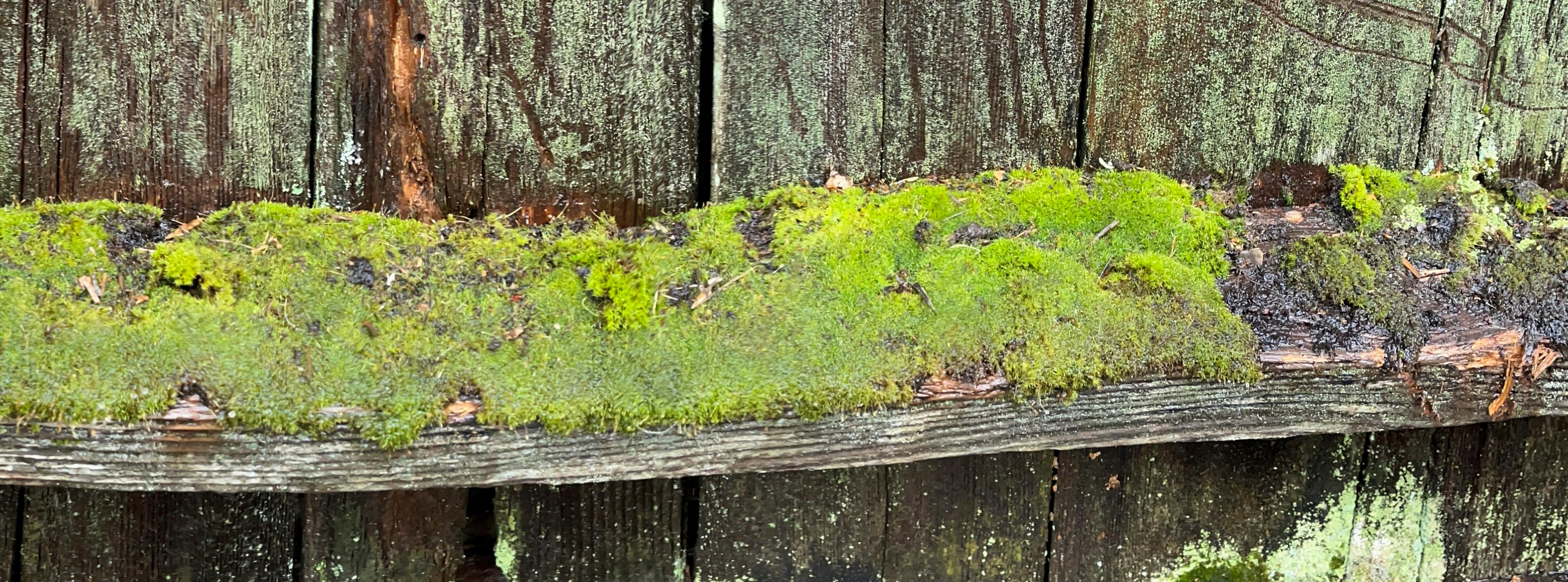
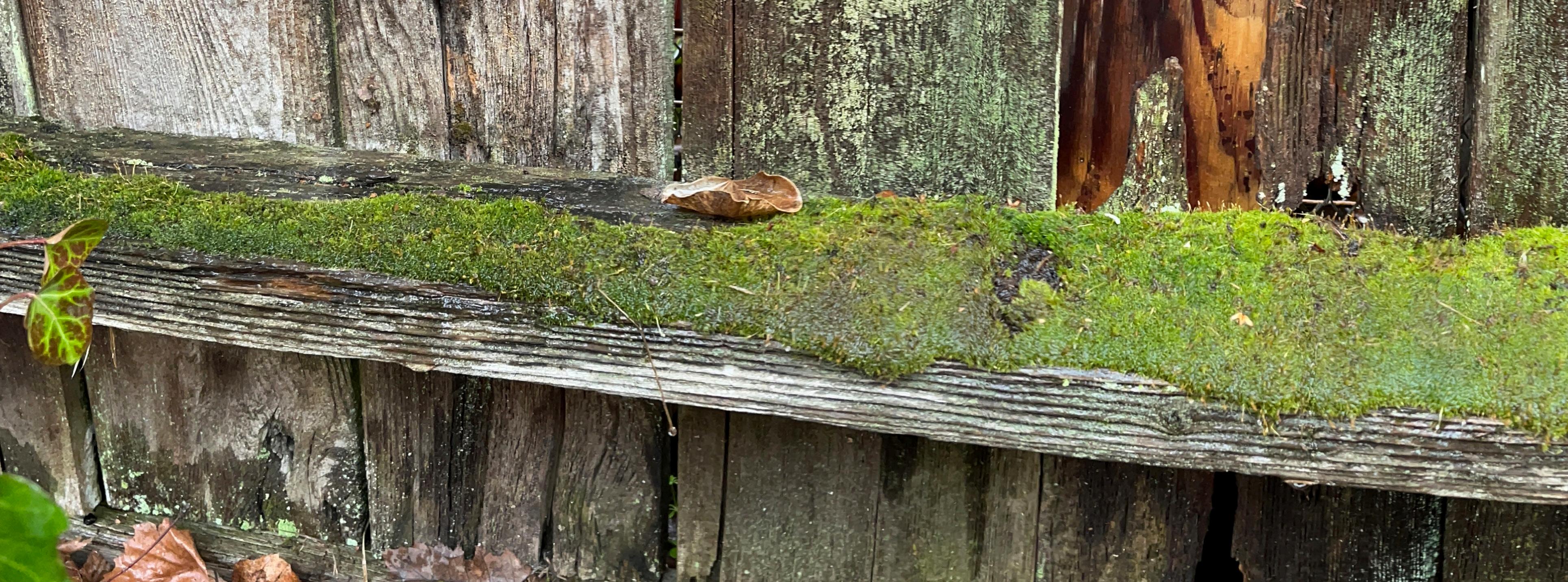
IMAGE: Backyard Moss

SCAFFOLDS
PART 1
PATTERN 01
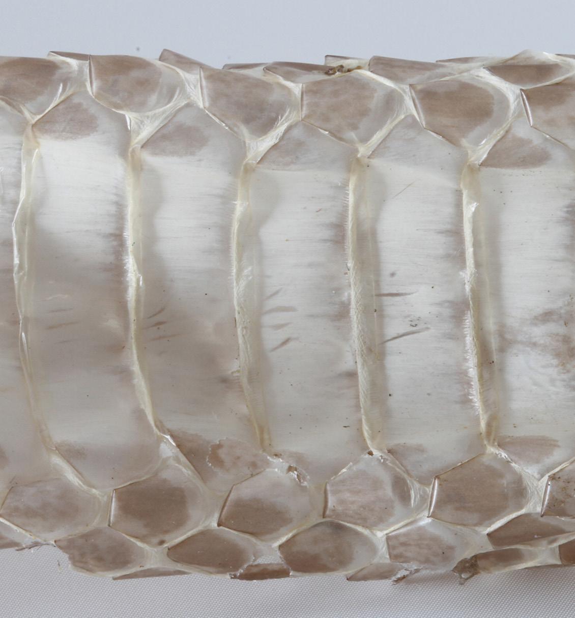
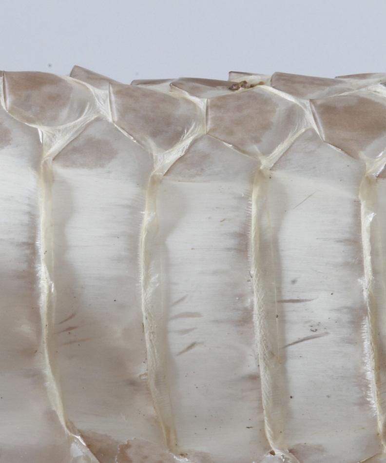
SNAKE SKIN BELLY
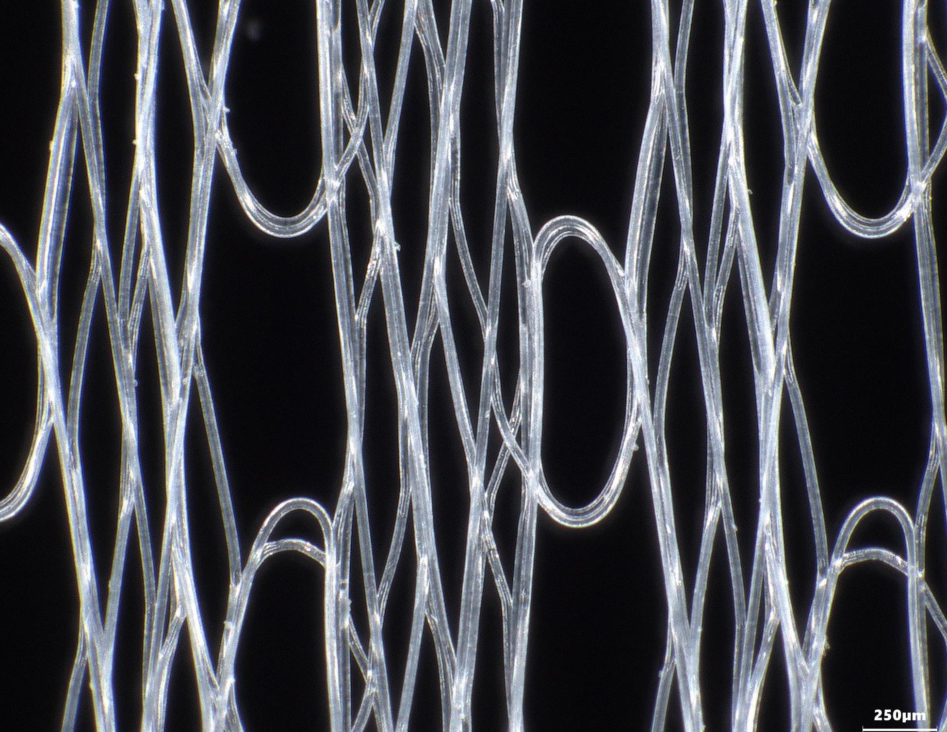
In this pattern, the aim was to try and create a structure that would be thick enough to hold up when examined. This structural pattern mimics that of a snake skin.
The speed for this print was F600.

IMAGE:
Snake Skin Image Detail
Snake Skin Cluster

PATTERN 02
HEDGEHOG
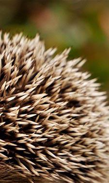
In this pattern, I wanted a complex grouping of triangles. Only after making the pattern did I see the resemblance with the back of a hedgehog.
The speed for this print was F600.
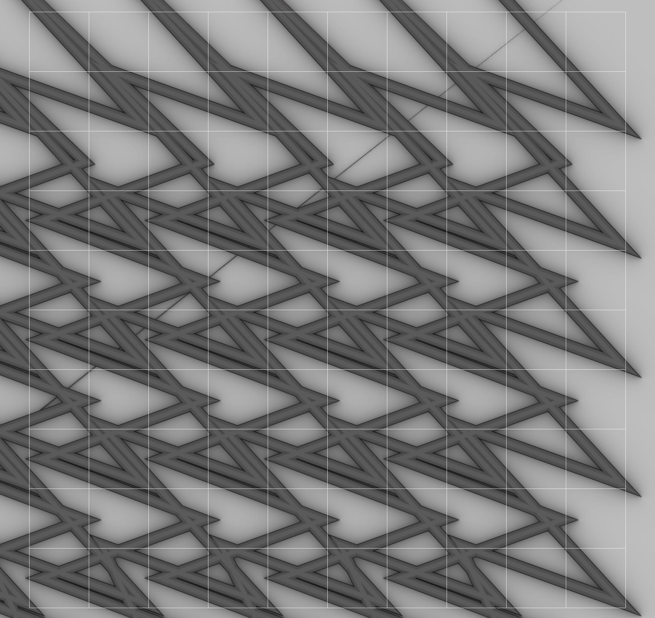
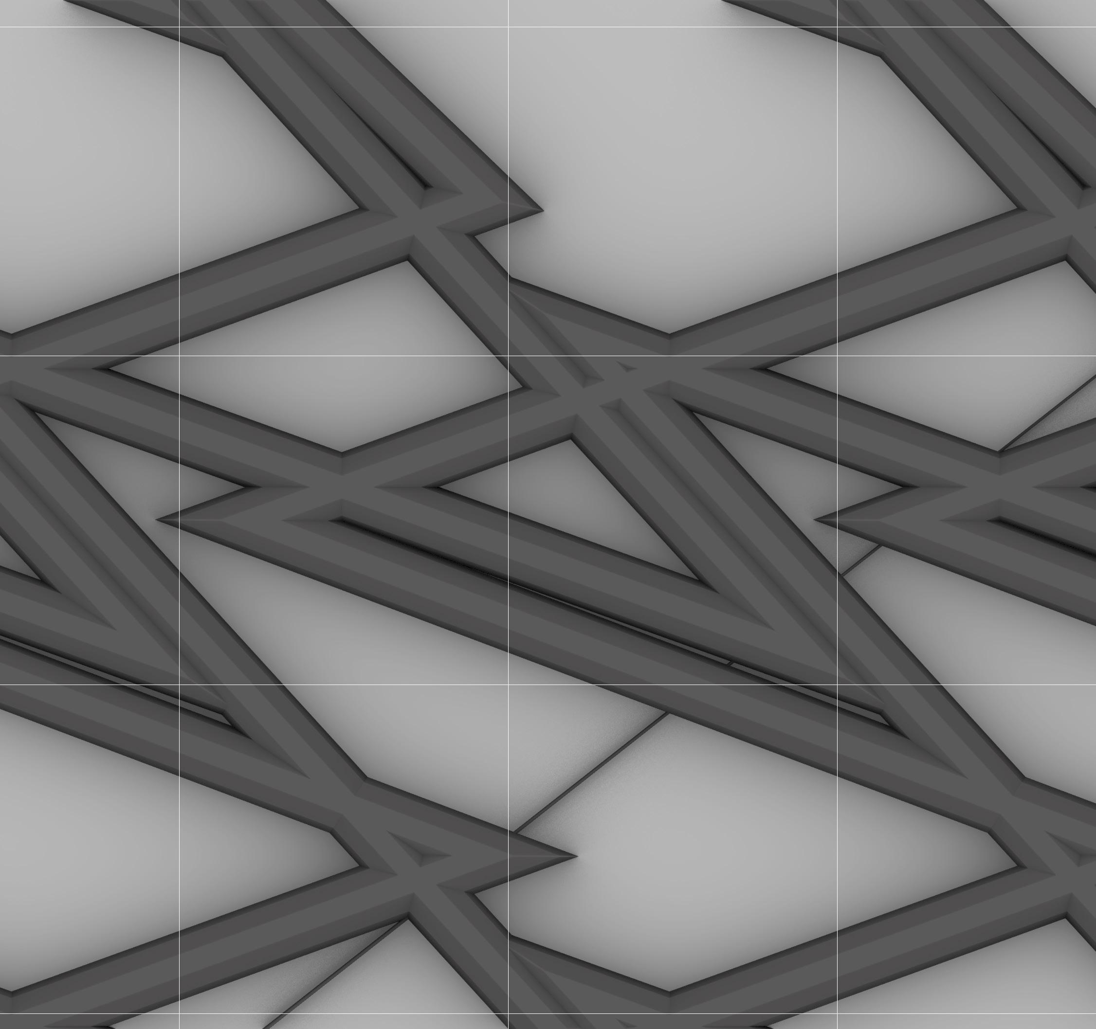
IMAGE:
Hedgehog Image Detail
Hedgehog Cluster

PATTERN 03
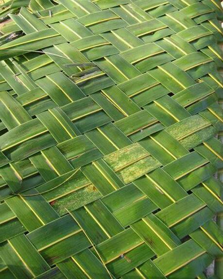
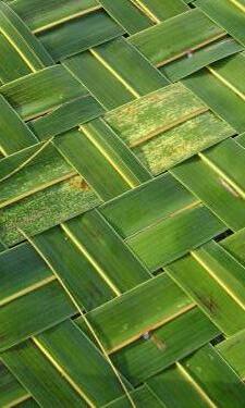
WOVEN BASKET
In this pattern, I wanted to mimic some of natures more organized patterns. Those sometimes influenced by human organization.
The speed for this print was F600.
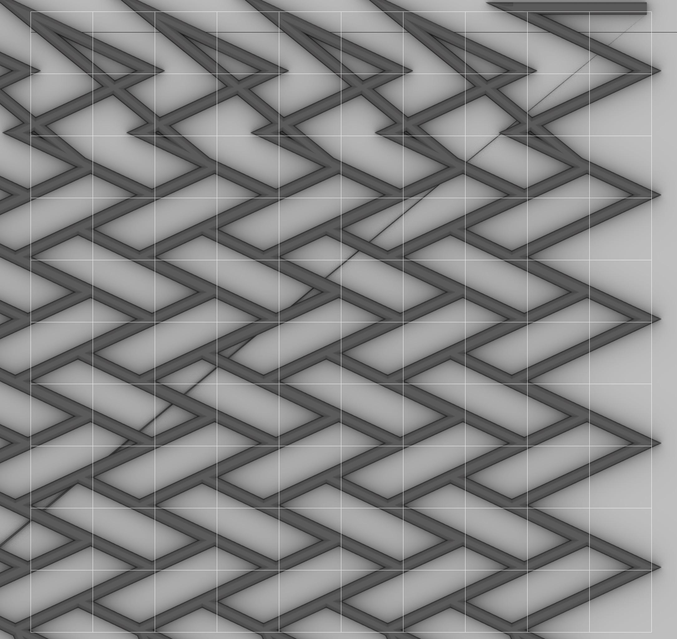
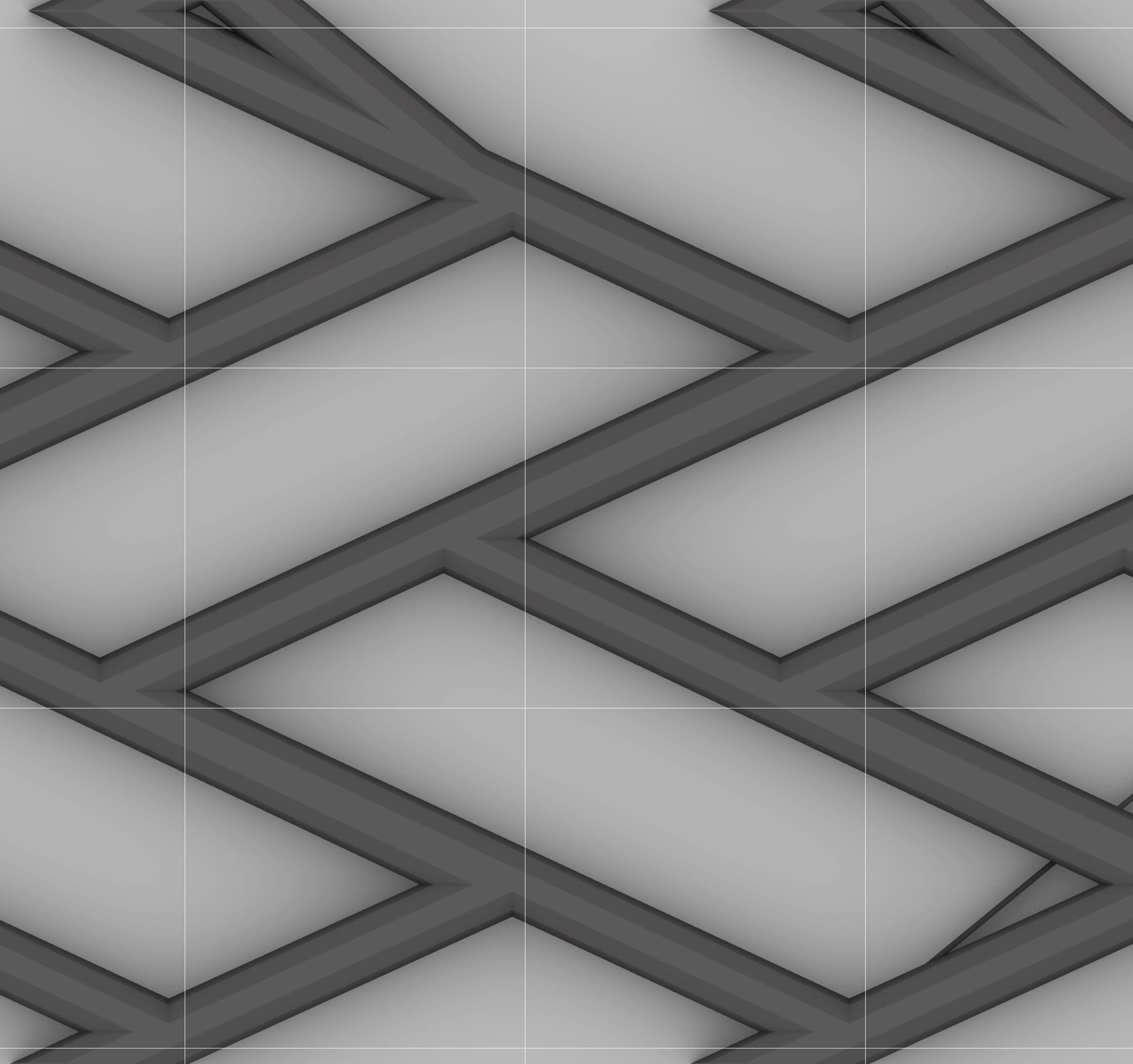
IMAGE:
Woven Basket Image Detail
Woven Basket Cluster
PATTERN 04
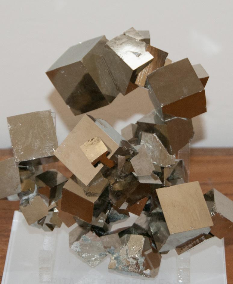
PYRITE
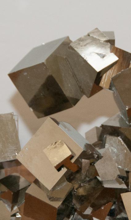
In this pattern, the aim was to create a geometric structure to mimic the form of Pyrite. This mineral naturally forms perfect cubes.
The speed for this print was F600.
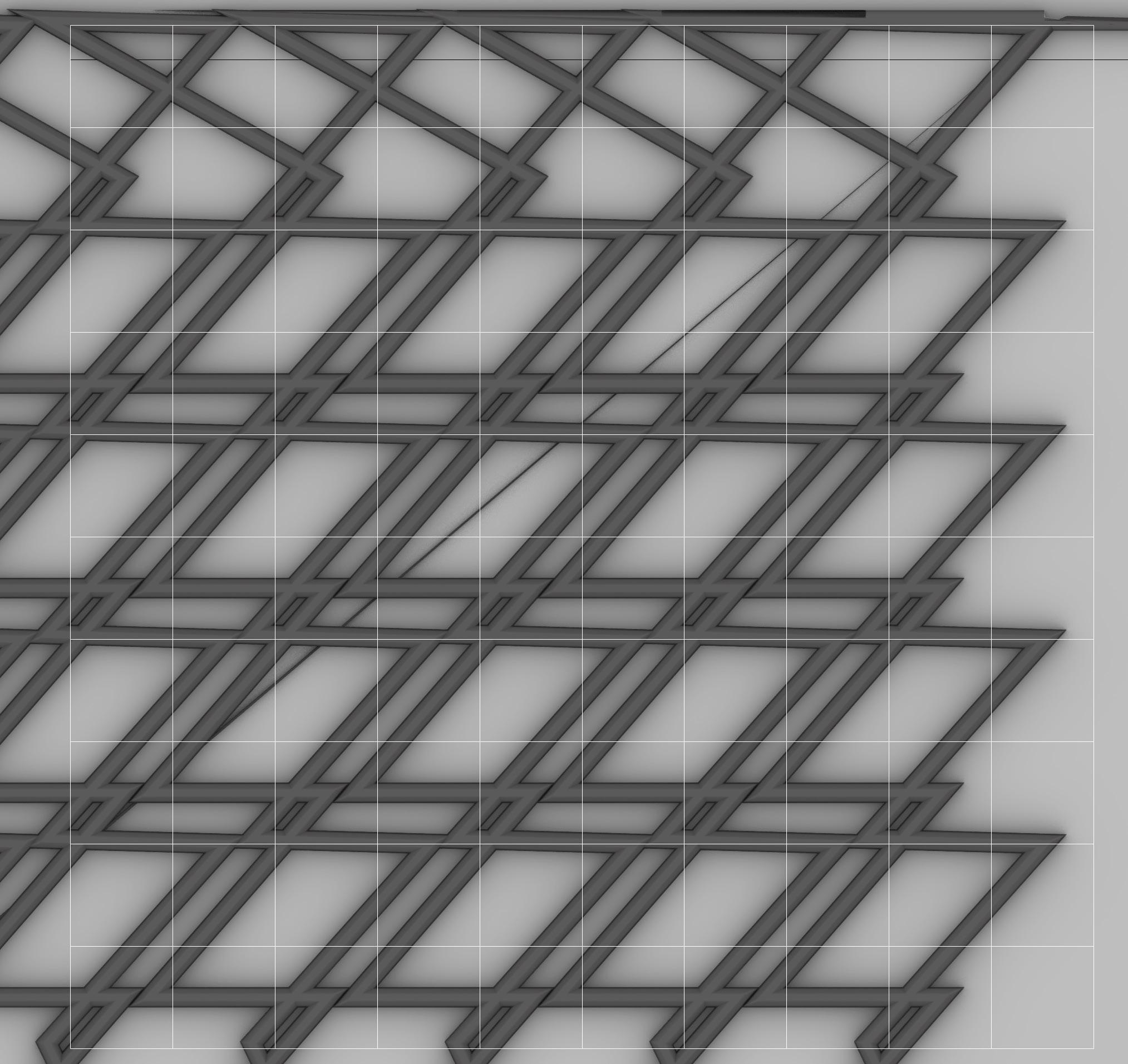
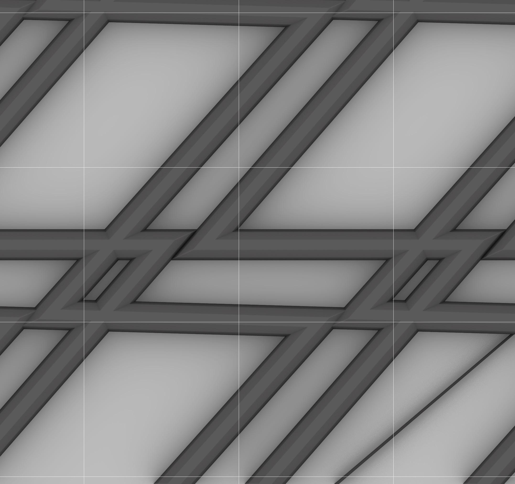
IMAGE:
Pyrite Image Detail
Pyrite Cluster
PATTERN 05
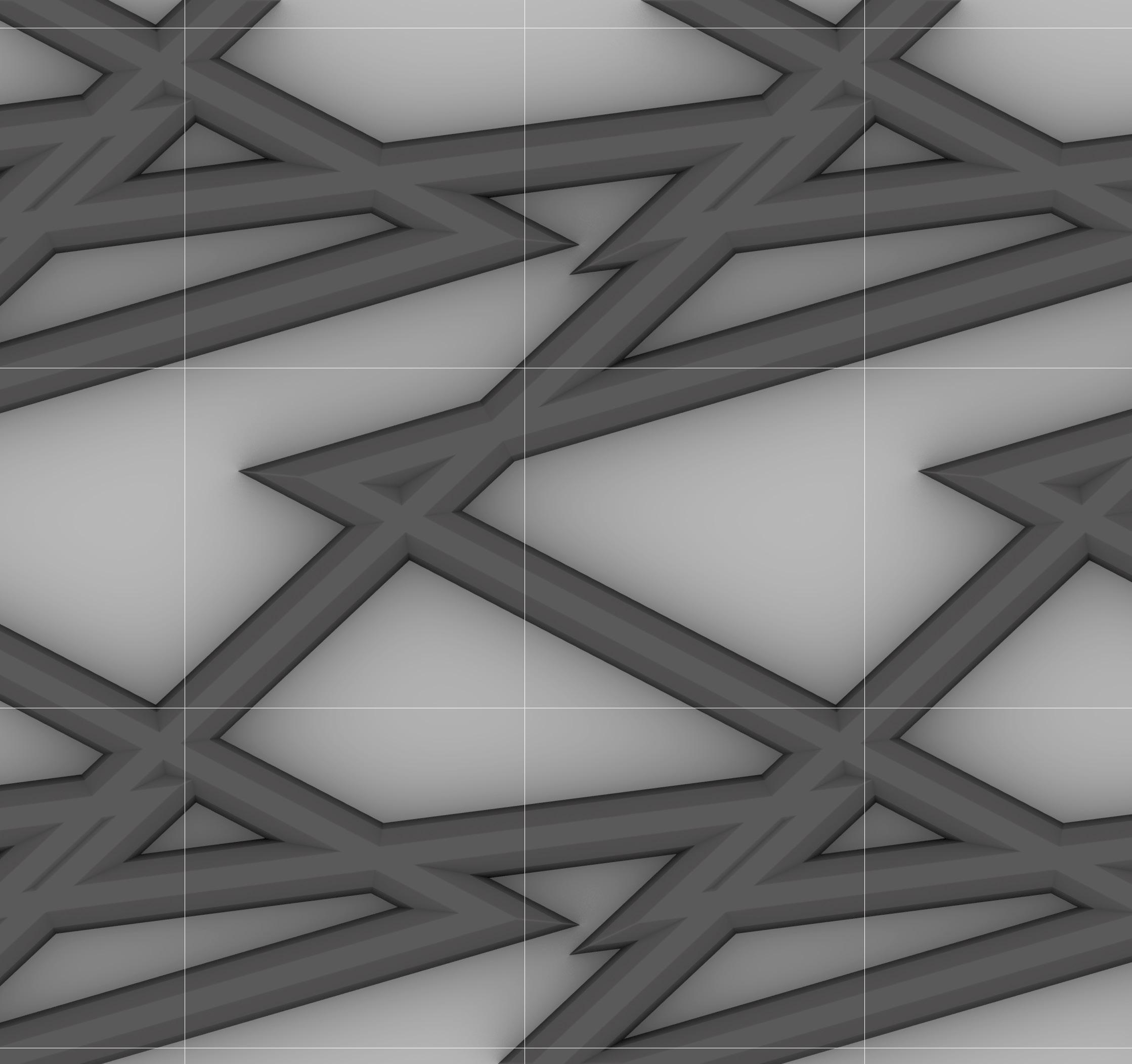
GOLDEN BARREL CACTUS
In this pattern, I wanted to show the organization of the thorns on a golden barrel cactus. This pattern ended up looking much more three dimensional than I was originally expecting.
The speed for this print was F600.
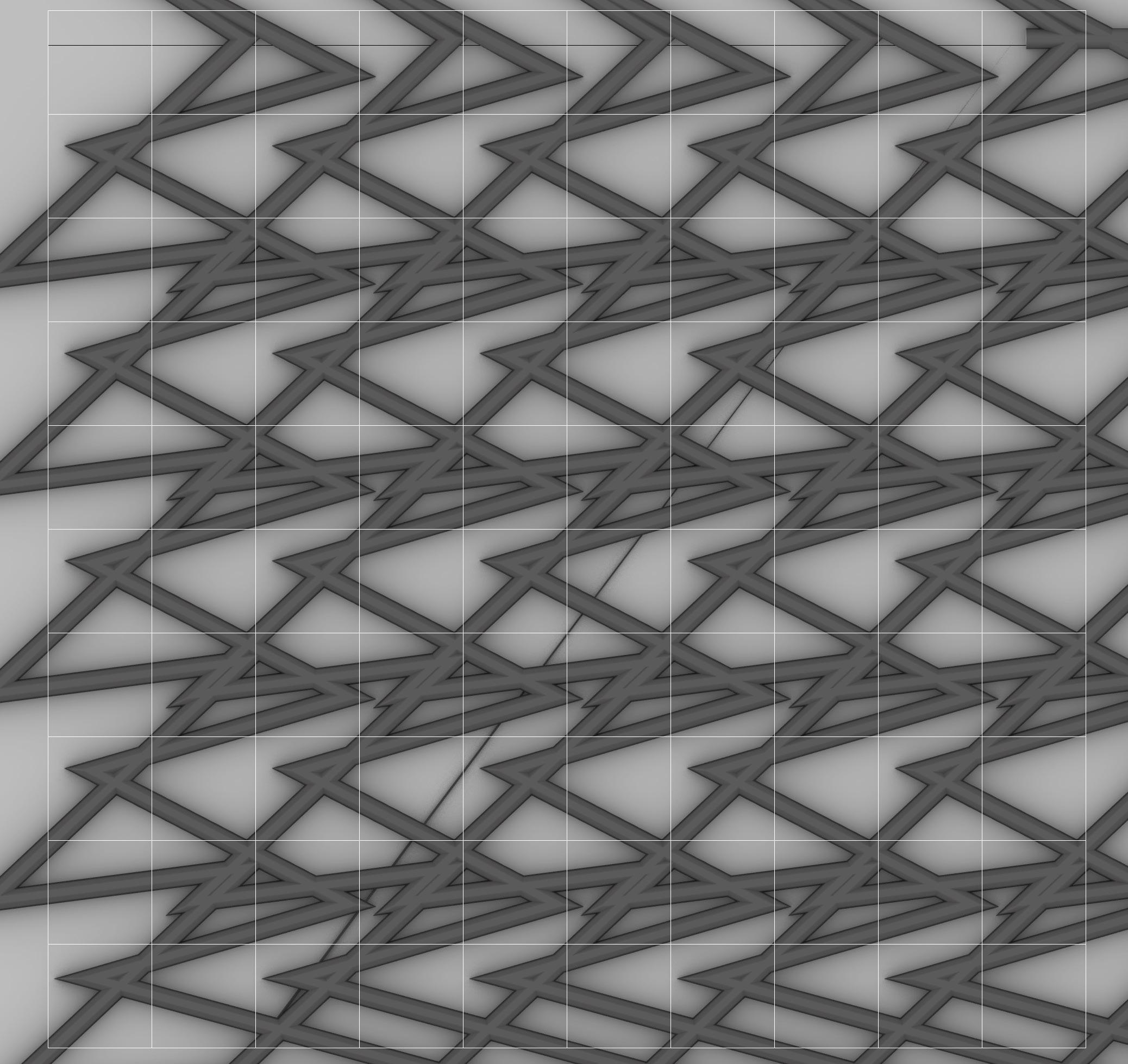
IMAGE:
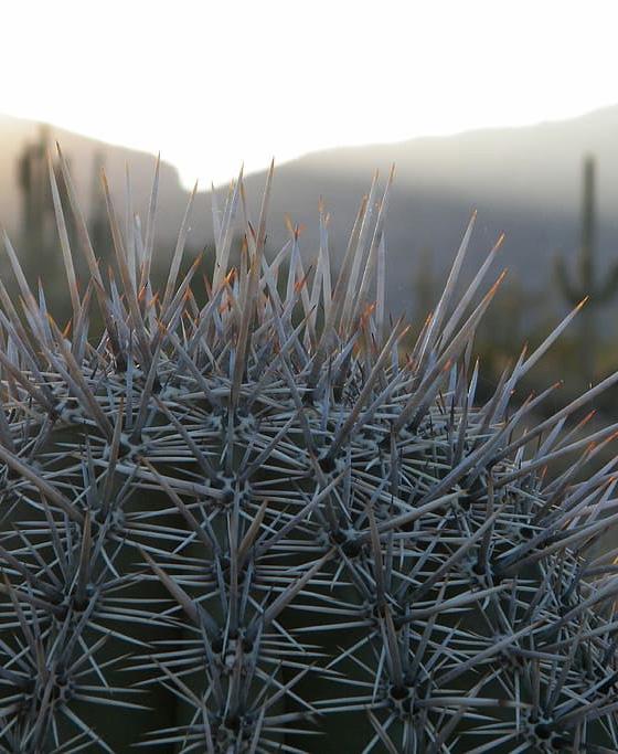
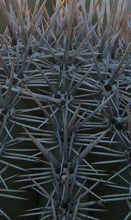
Golden Barrel Cactus Image Detail
Golden Barrel Cactus Cluster
1 mm x 1 mm
PATTERN 06
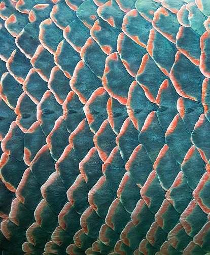
FISH SCALES
In this pattern, the aim was to try to create a good structural connection for the pattern while still occupying minimal space/material.
The speed for this print was F600.
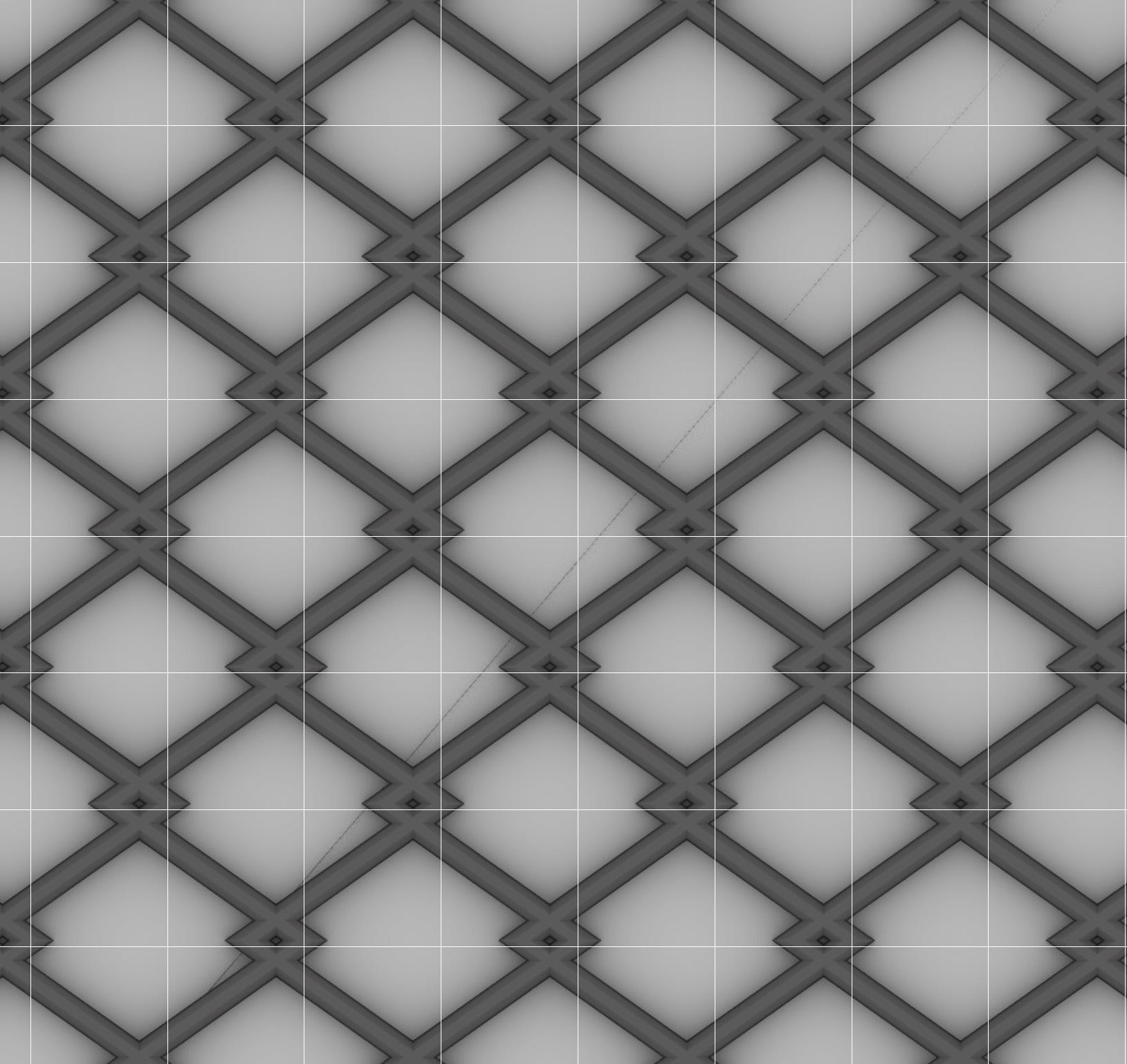
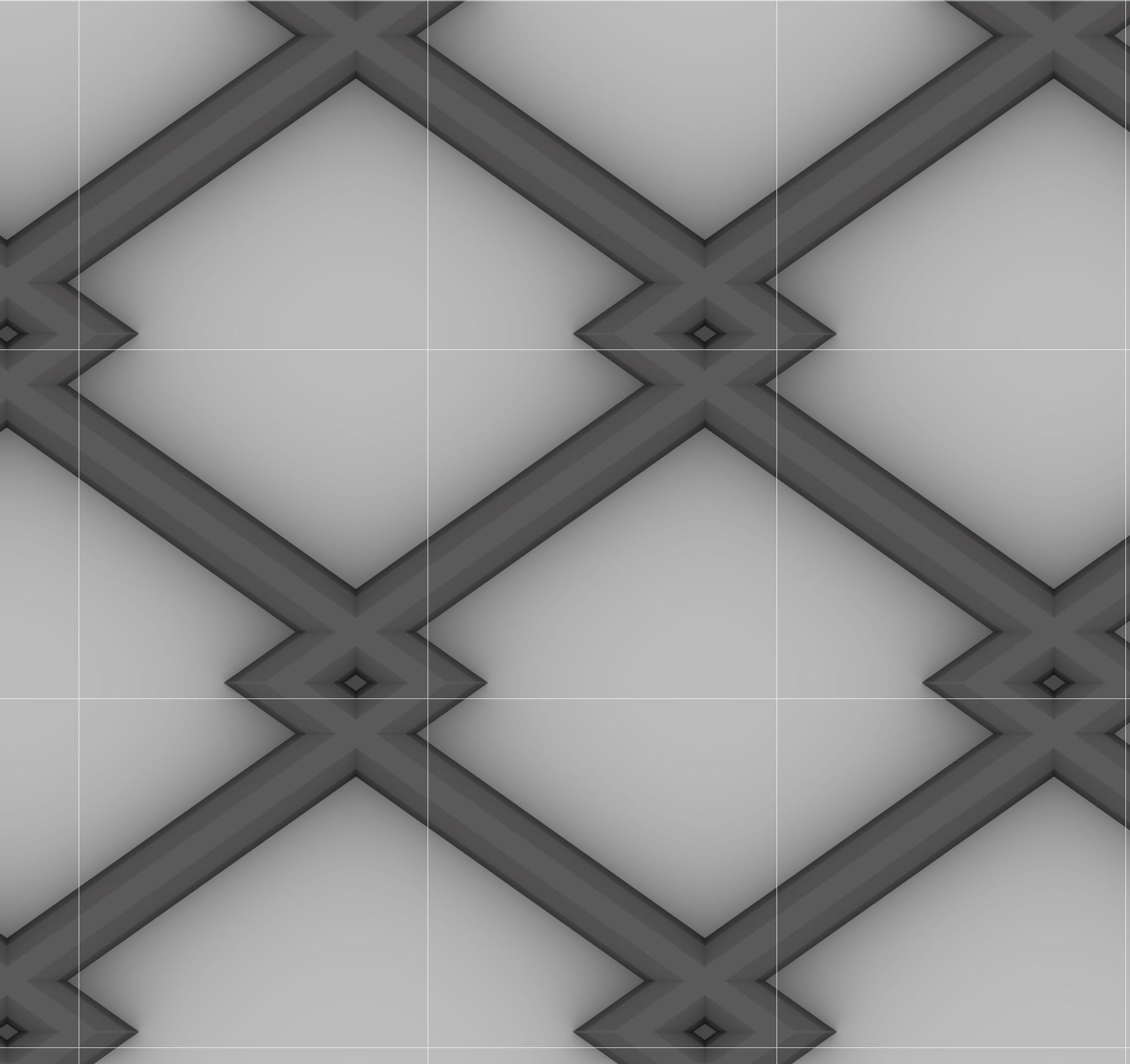
IMAGE:
Fish Scales Image Detail
Fish Scales Cluster
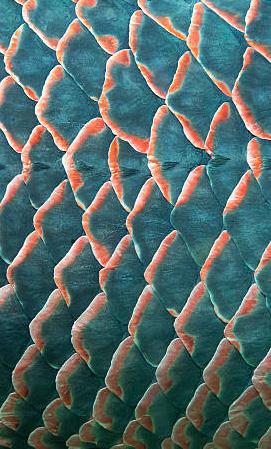
1 mm x 1 mm
PATTERN 07
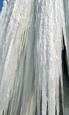
ICICLE
In this pattern, I mimicked the pattern of icicles, while also trying to create a knit like structure that can stretch and contract while keeping it’s structure intact.
The speed for this print was F600. 1
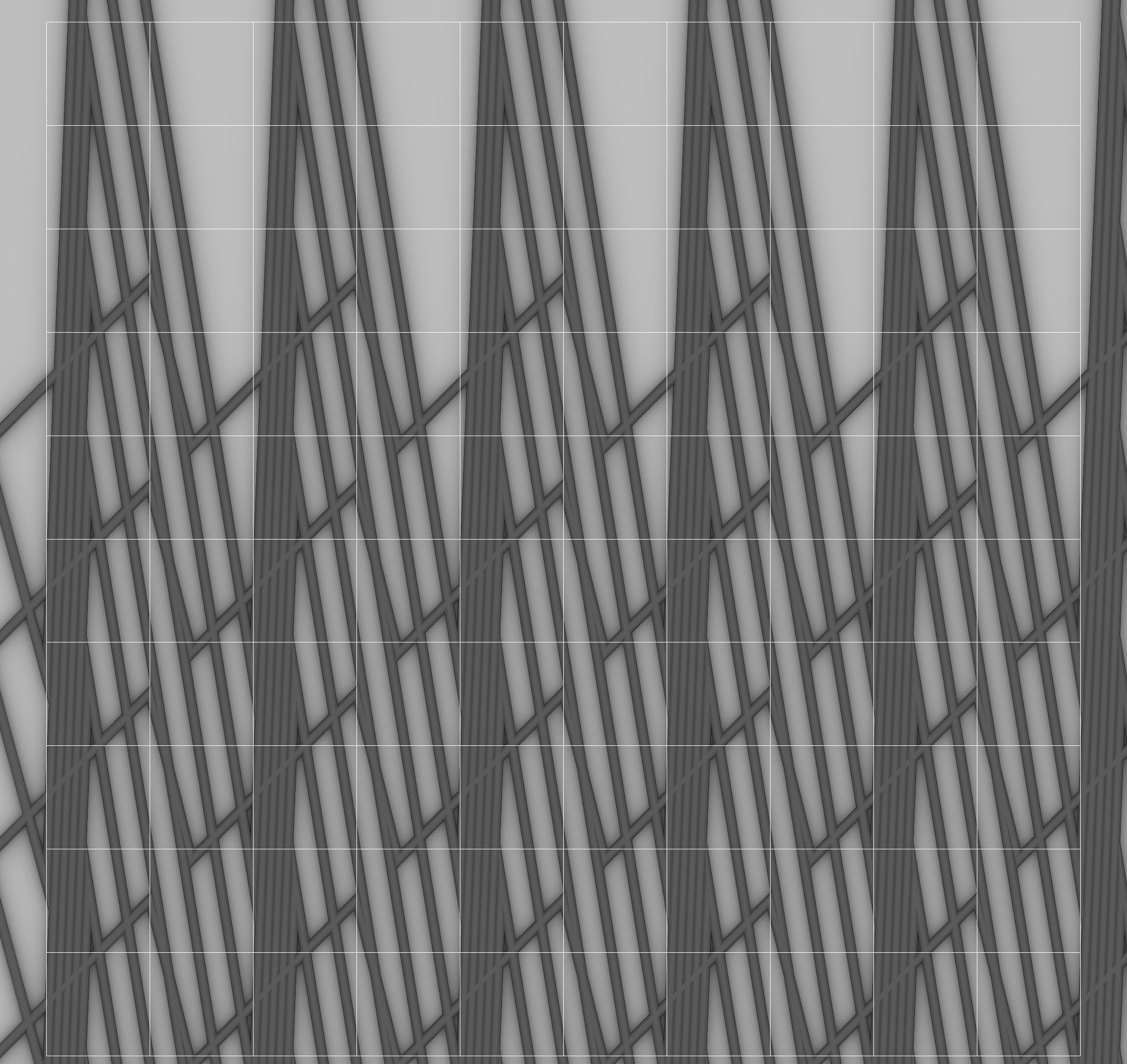
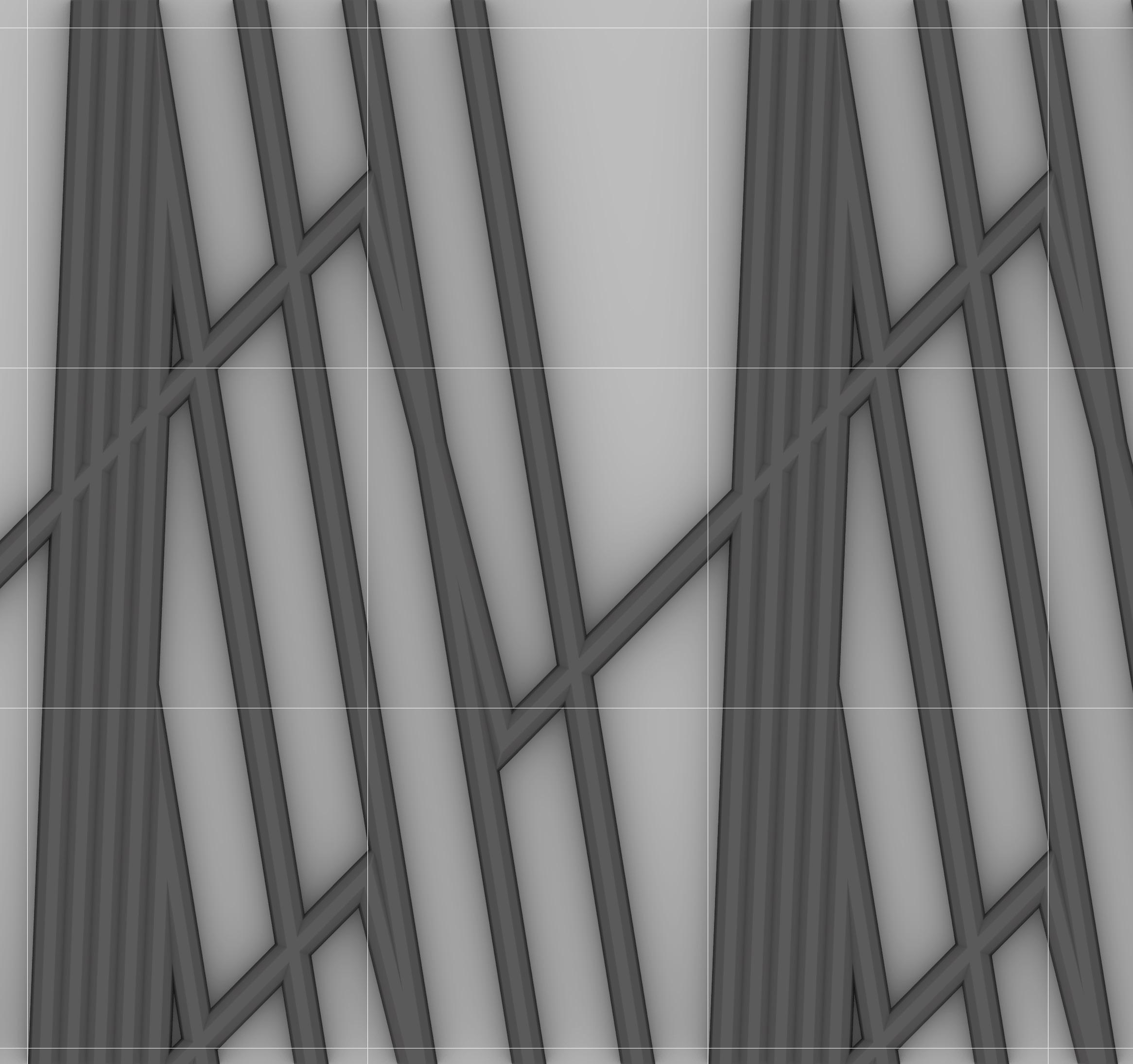
IMAGE:
Icicle Image Detail
Icicle Cluster

1 mm x 1 mm
PATTERN 08
RIPPLE
In this pattern, the aim was to create as many lines as possible on one pattern. The result created this beautiful almost radial pattern that looks like a ripple from a water droplet.
The speed for this print was F600.
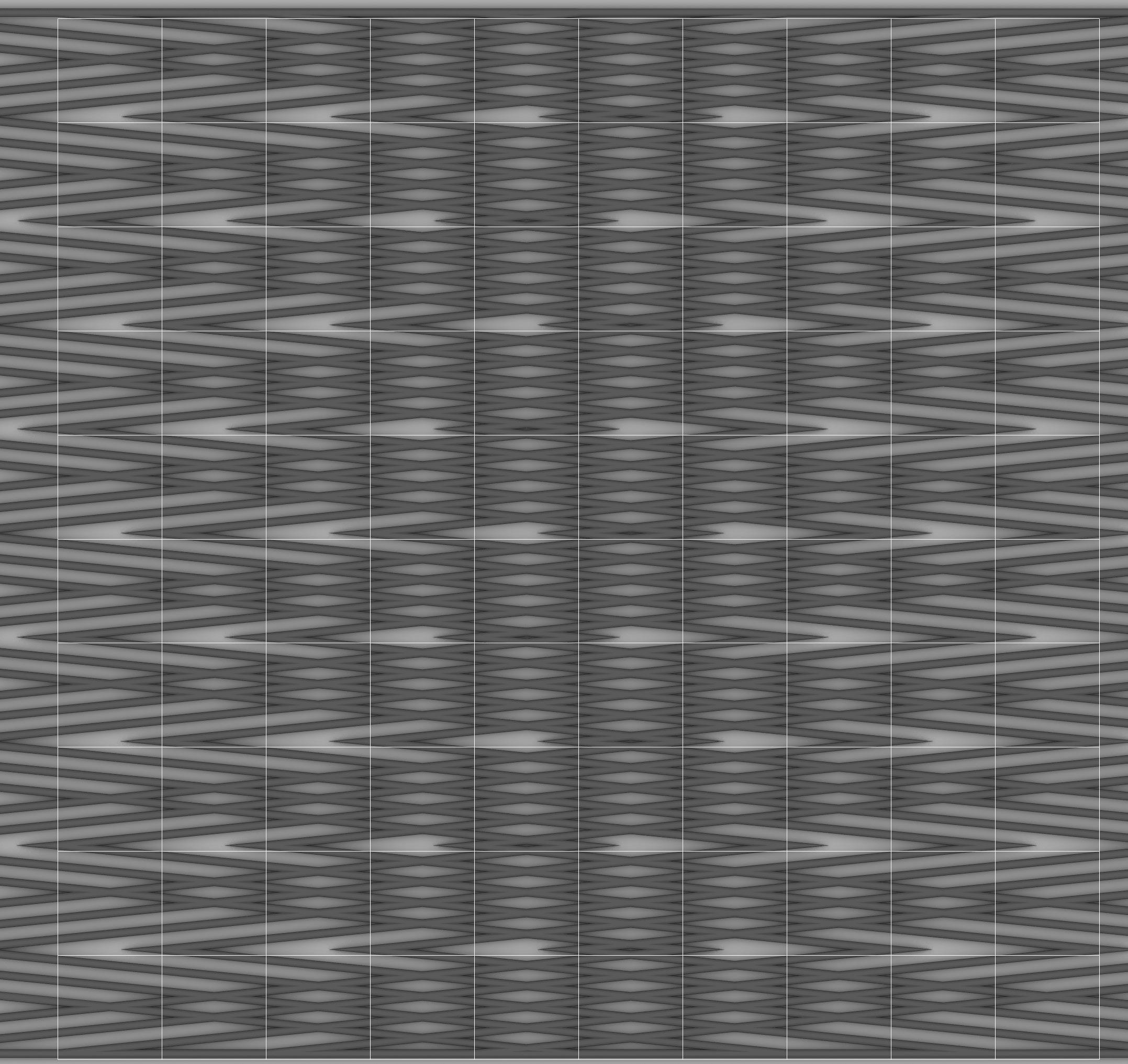
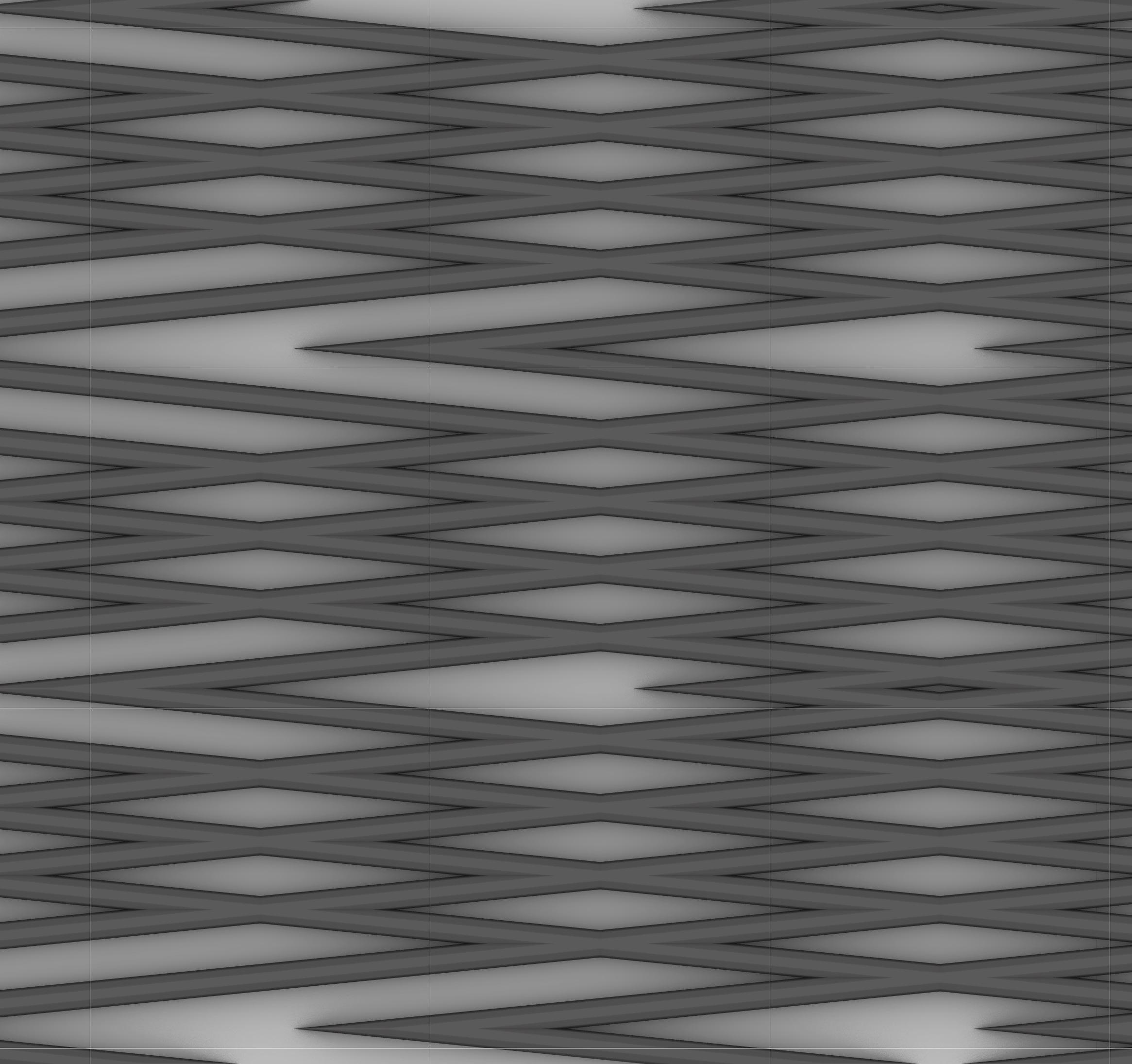
IMAGE:
Ripple Image Detail
Ripple Cluster


PATTERN 09
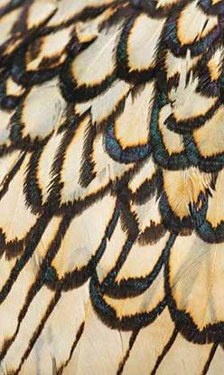
TAIL FEATHERS
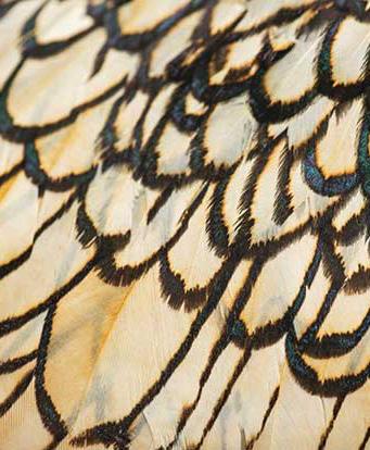
In this pattern, the goal was to overlap the lines just enough to connect the pattern seamlessly through the printing process. This pattern was inspired bird feathers and how they fit together.
The speed for this print was F600.
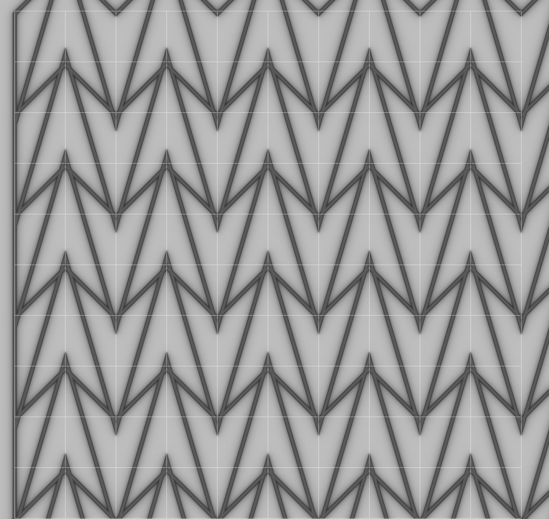
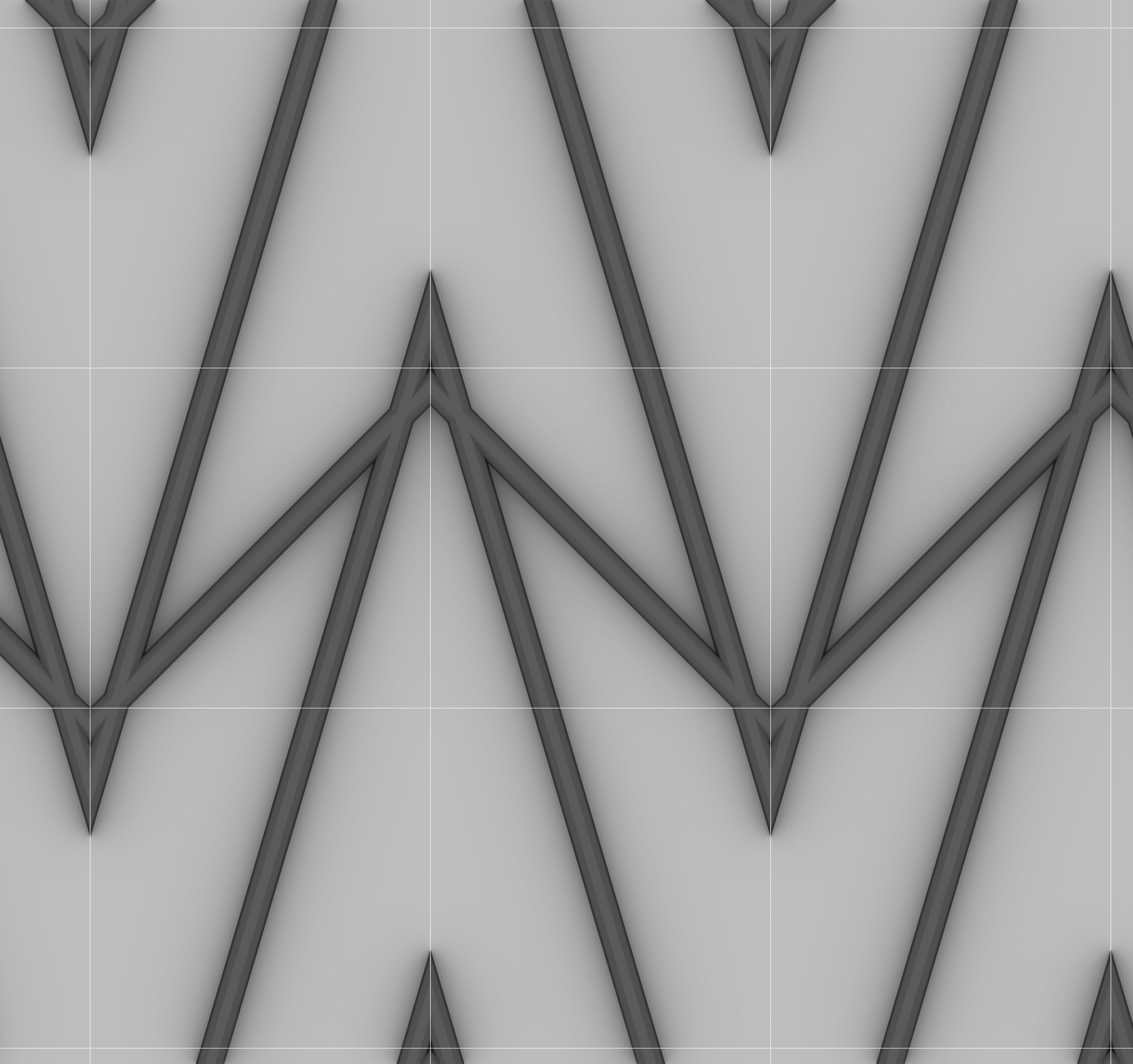
IMAGE:
Tail Feathers Image Detail
Tail Feathers Cluster
1 mm x 1 mm
3D PRINTS
ITERATIONS AND ANALYSATION
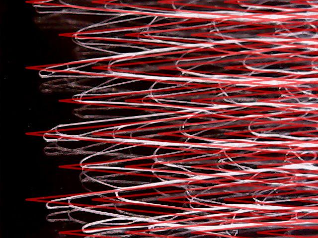
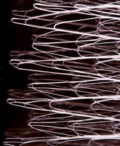
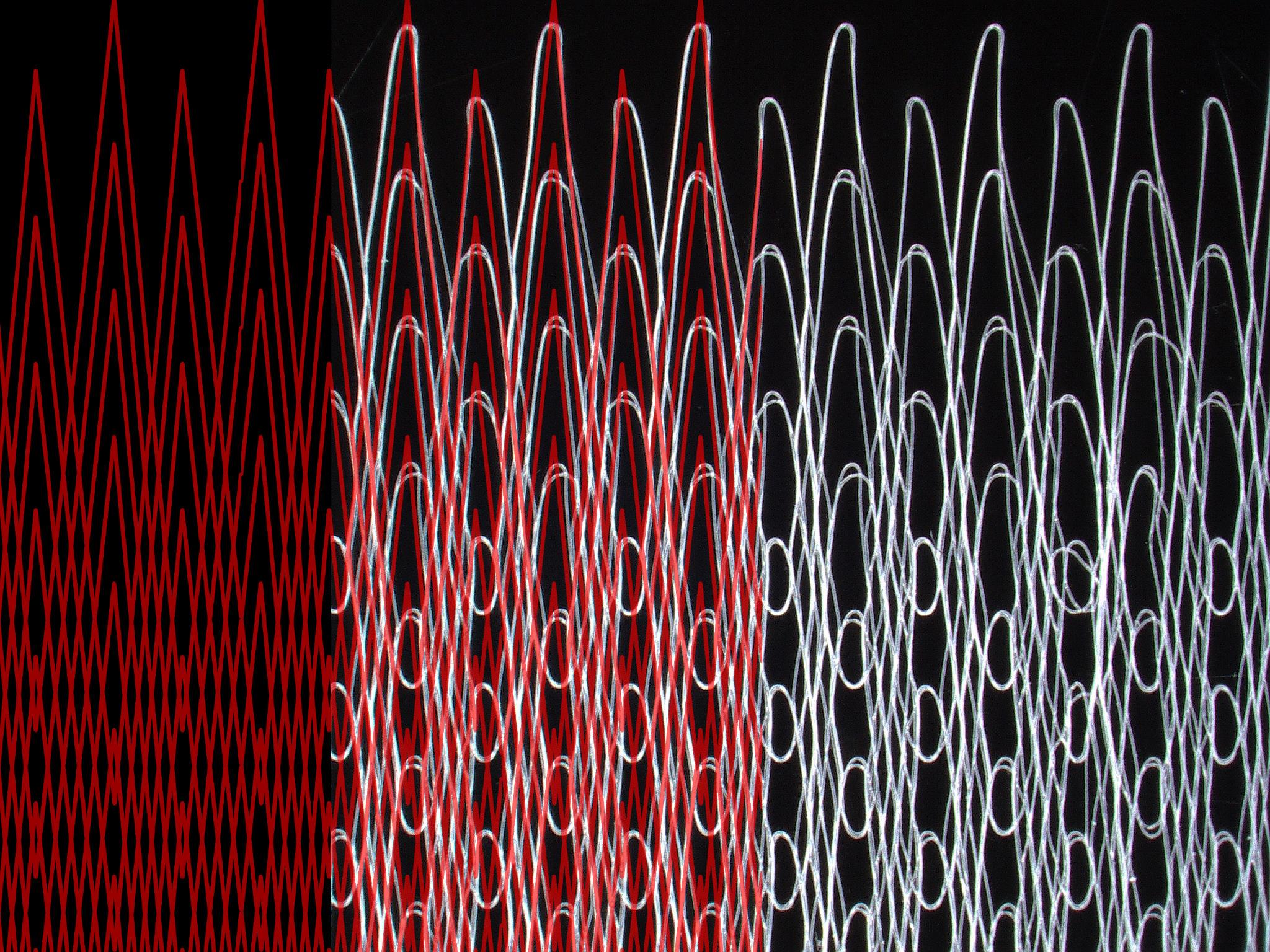
Our intention here was to begin test printing on the micro scale in order to be able to understand how these patterns would be possible.

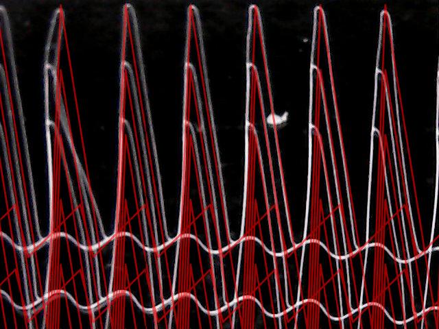
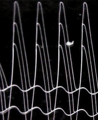
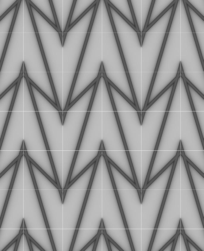
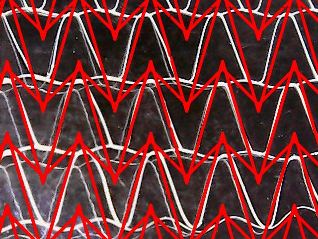
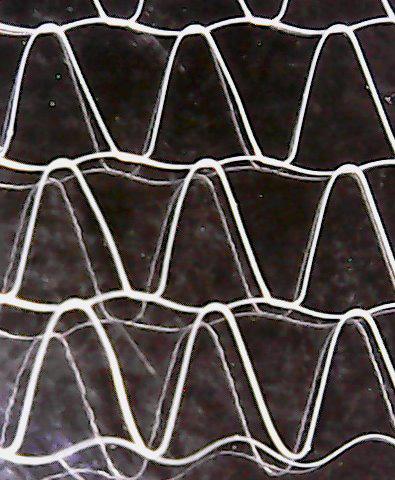
IMAGE:
Comparison Images through out the test printing process. These are side by side comparisons of digital vs. physical results.



Print 3.1
Final Print 4.1
Print 3.2
Final Print 4.2
Print 3.3
Final Print 4.3
FINAL 3D PRINT
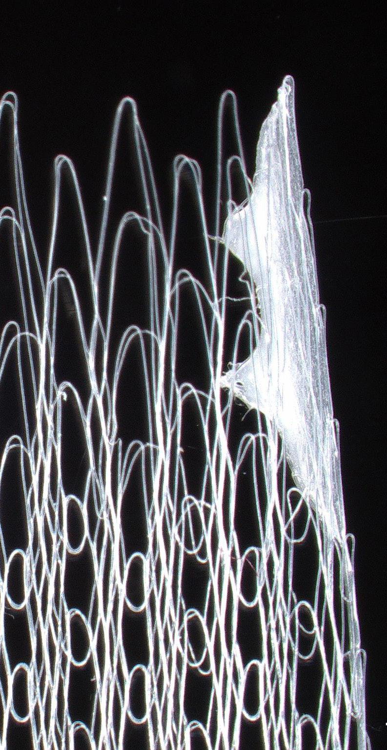
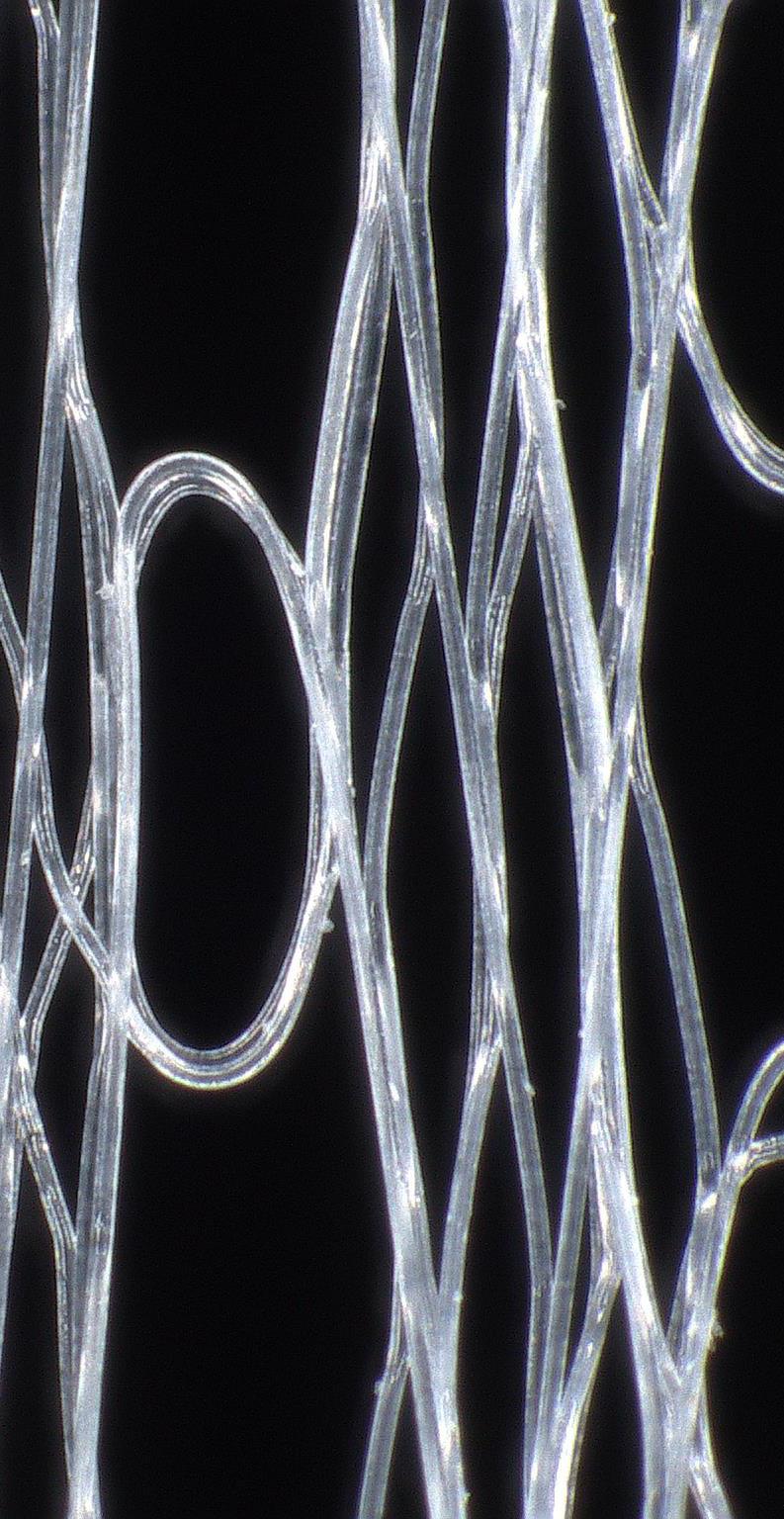
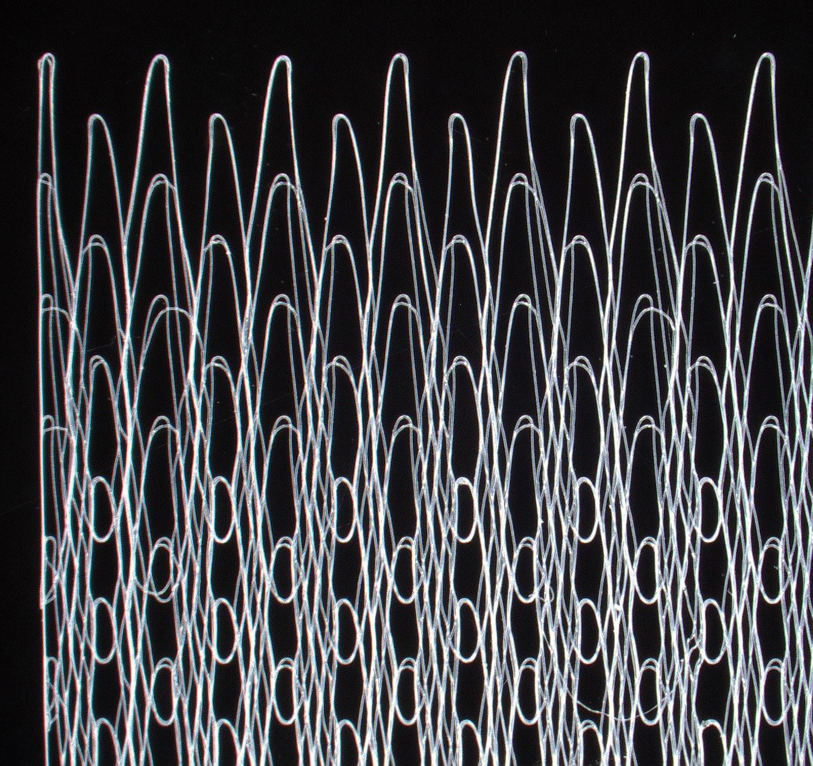
Displayed here is the final 3D Print of the custom scaffold. The intricacies you can see through the microscope are truly amazing. One thing that interested me was at the start off point of the scaffold there was a large clump of material. Another interesting addition was the way the scaffold moved when stretched. It really behaved like nylon fabric in the sense that is would stretch and recoil.
LOCATION
LAWRENCE LIBRARY READING ROOM
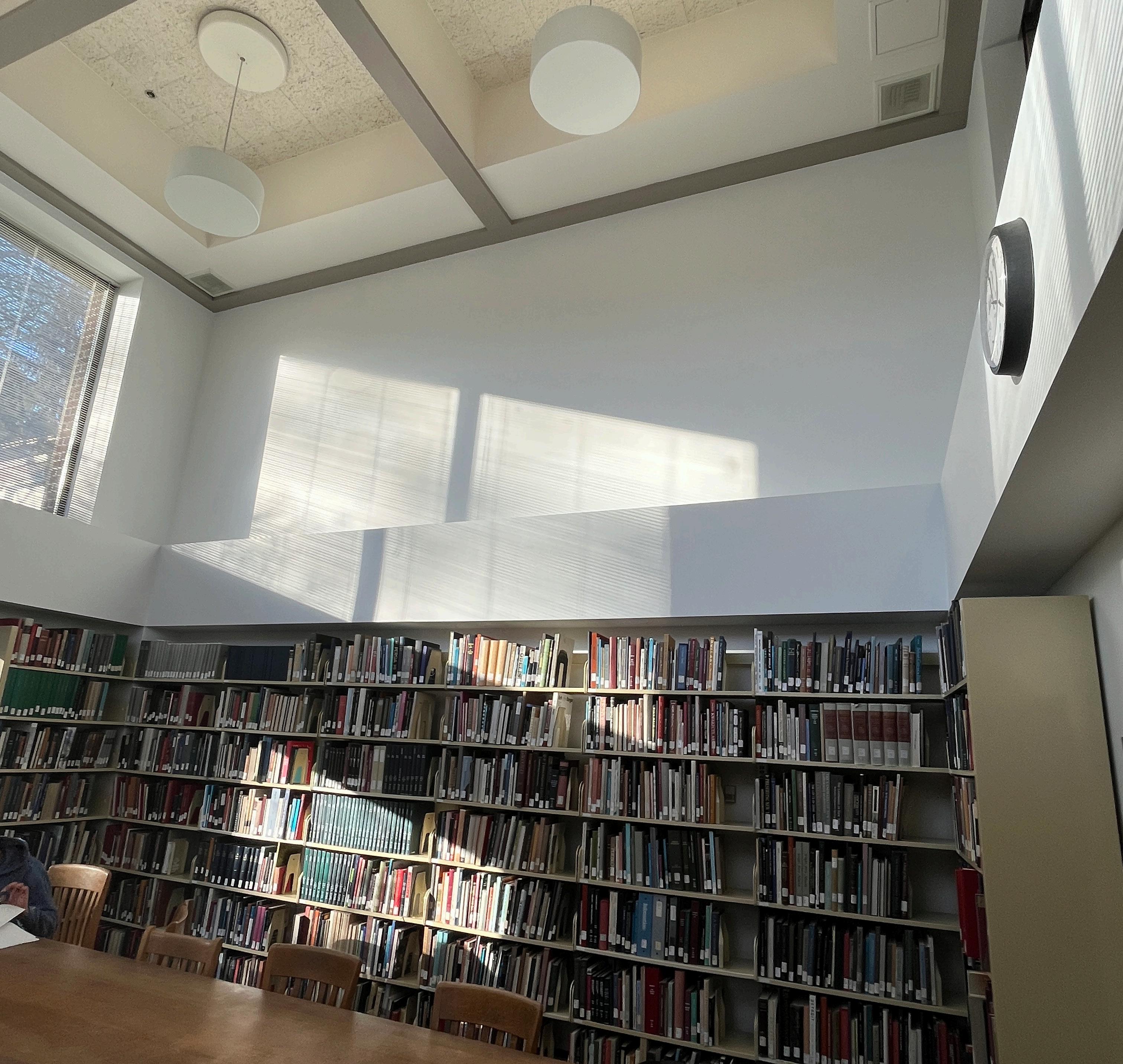
When choosing a location in Lawrence I personally love the library’s reading room. This room is located on the south side of Lawrence and is usually unoccupied. I believe bringing in this living system here will be a living gem for university and the school of design.

LAWRENCE | 2ND FLOOR MEZZANINE
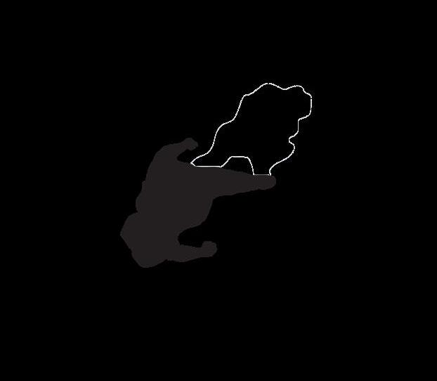
READING ROOM | 2ND FLOOR MEZZANINE
Reflected Ceiling Plan Main Library

LIDAR SCAN
READING ROOM
After trying to scan the room multiple times with 2D images, I was able to use a Lidar camera to capture the room in it’s entirety. This is a great way to enjoy the space and to find details you may have not known were there.
READING ROOM | NORTH ELEVATION
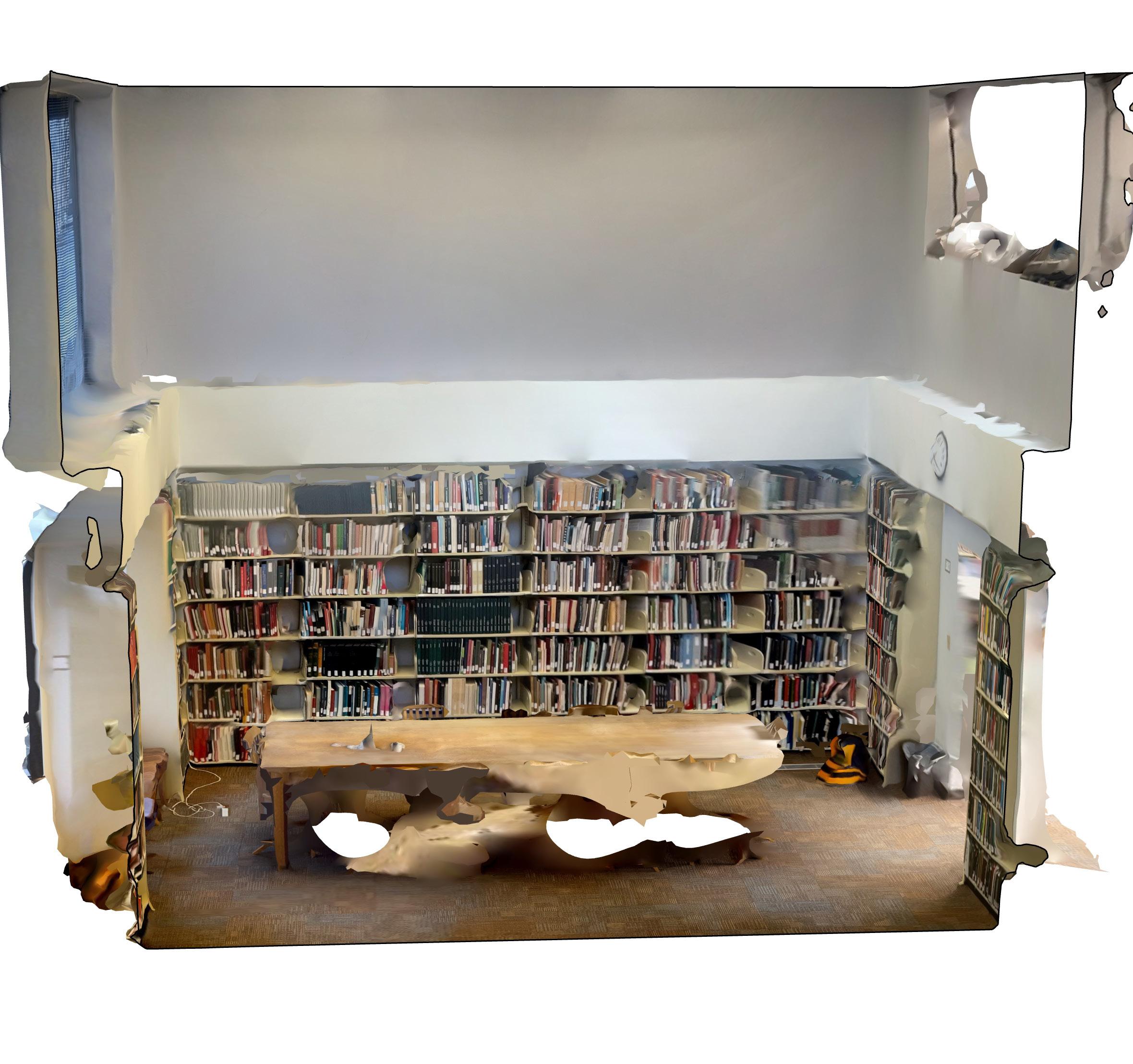
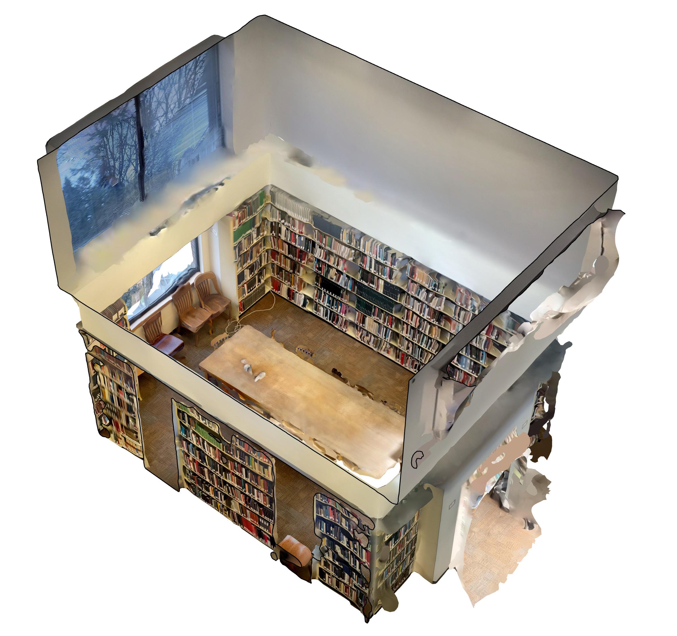
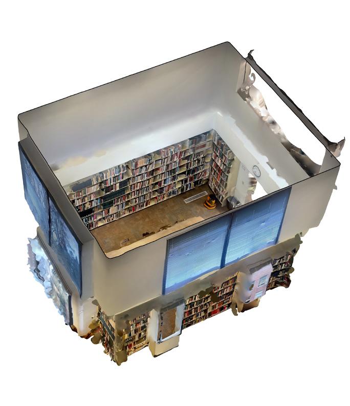
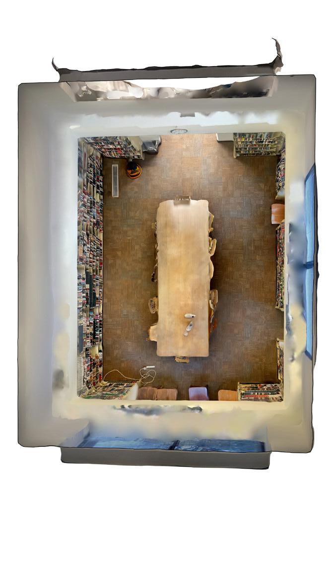

IMAGE:
1:1 SCALE MODEL
1 INCH = 1 FOOT
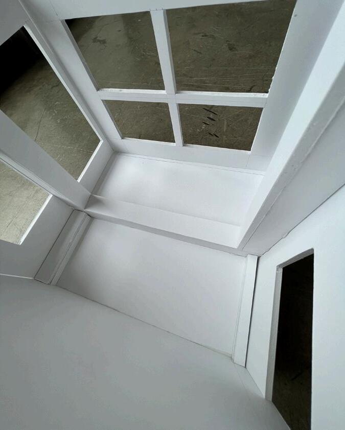
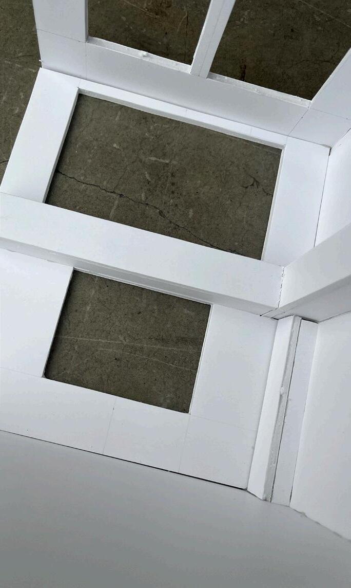
Once I understood the lay out and size of the room I built a 1:1 scale model of the space. This model helped to understand lighting, but was mainly used as a place holder as we began our string and nail models.
We were also able to capture the light readings through a lux meter. A typical room will usually measure 300-500 LUX. Outside on a cloudy day could read up to 1000 LUX, while a sunny day could be over 5000 LUX.
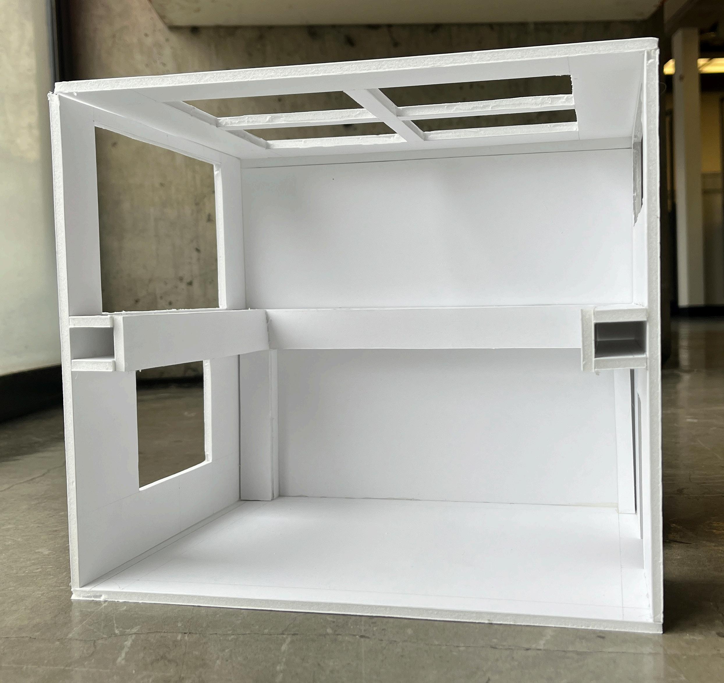

IMAGE: READING ROOM & SCALE MODEL OF READING ROOM
HALF SCALE PATTERNS
STRING AND NAIL MODELS
These nails are spaced at a 0.5”x0.5” grid meaning on the model each of these squares would be 1 foot x 1 foot. There were about 10 patterns in total, but I ended up choosing the bottom right image for its complexity and beauty. It also mimicked my first pattern that was inspired by a ripple in water.
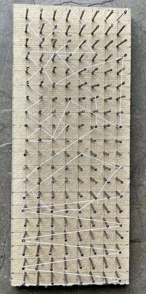
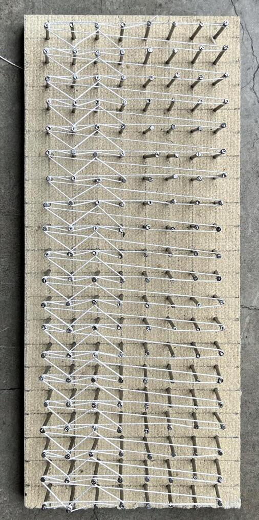
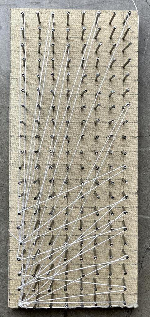
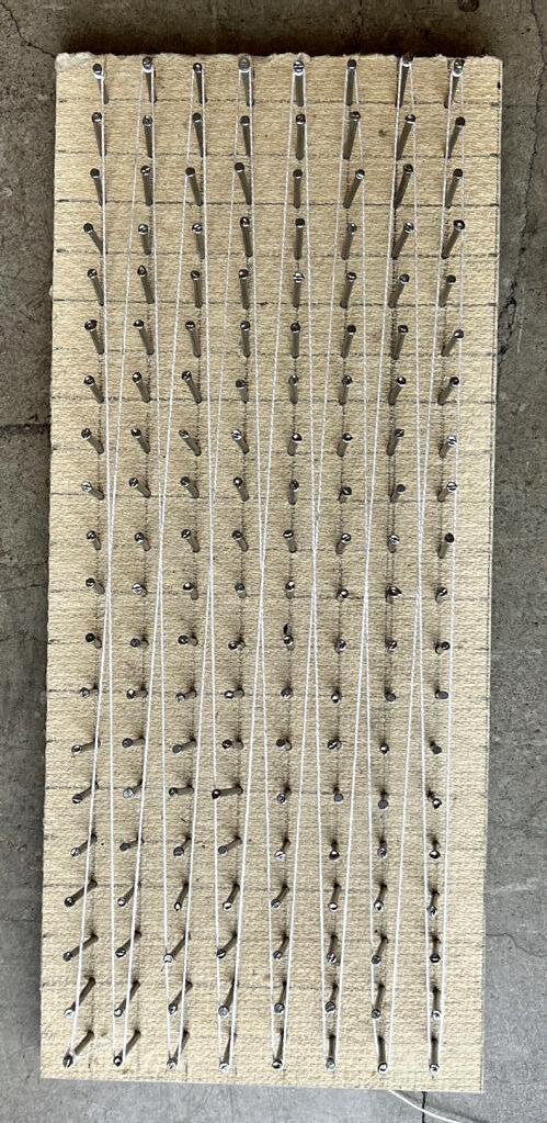
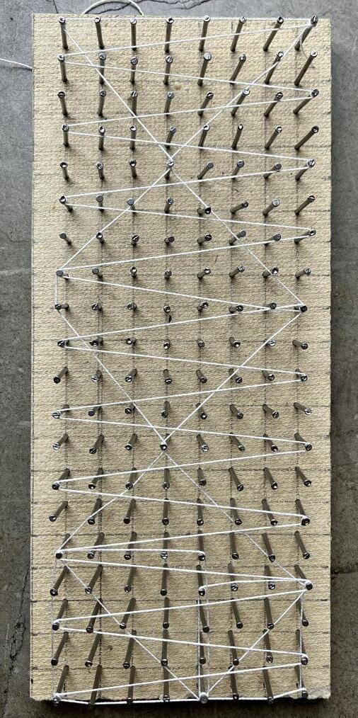
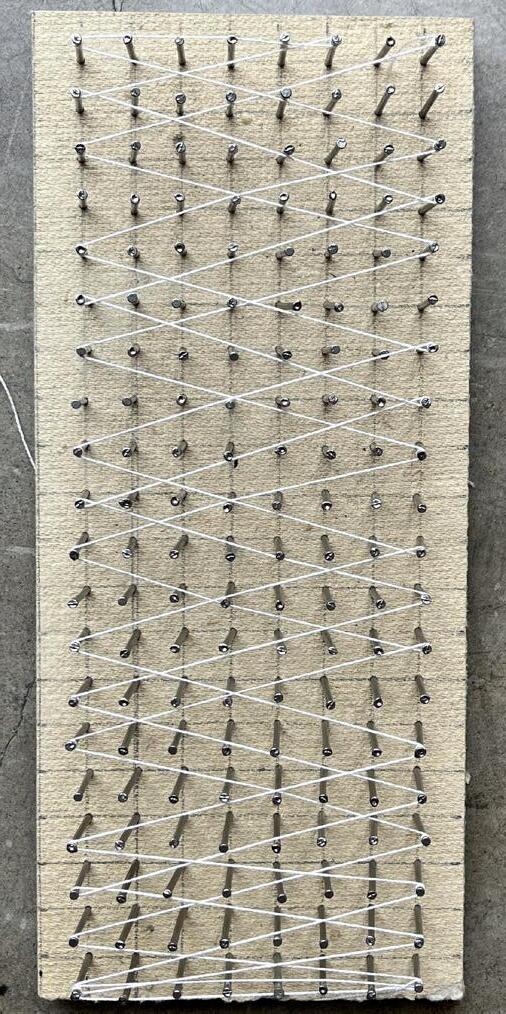
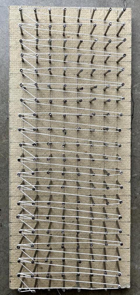
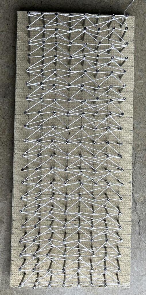
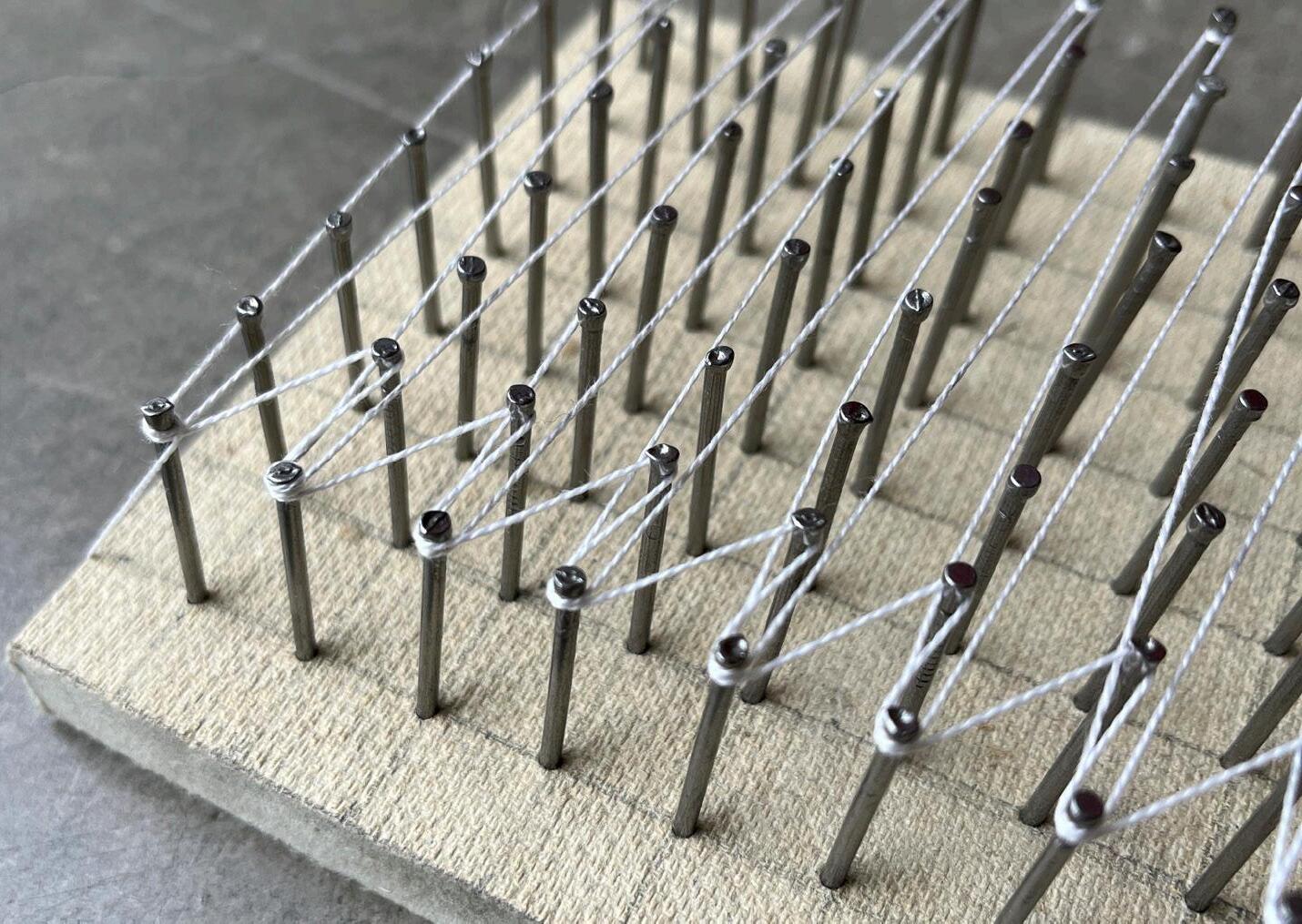
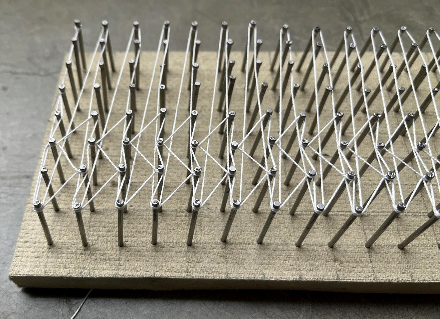
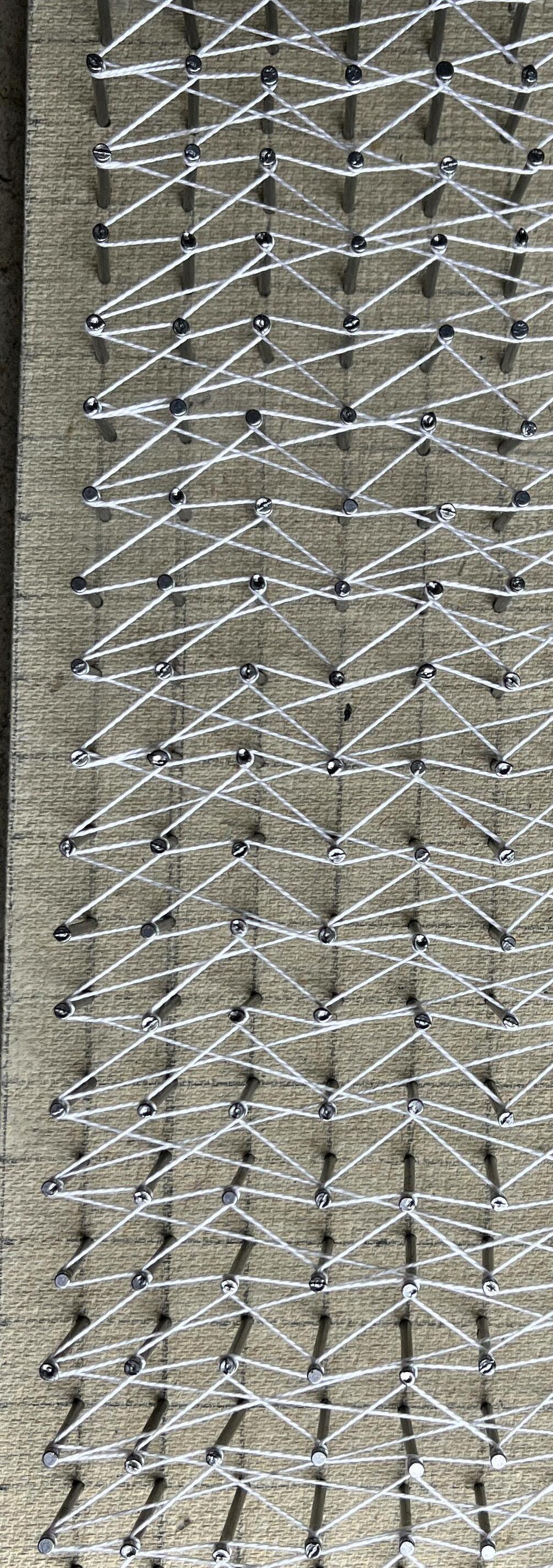
IMAGE: HALF SCALE MODEL OF STRING IN SPACE
BLOCK PATTERNS
ITERATIONS
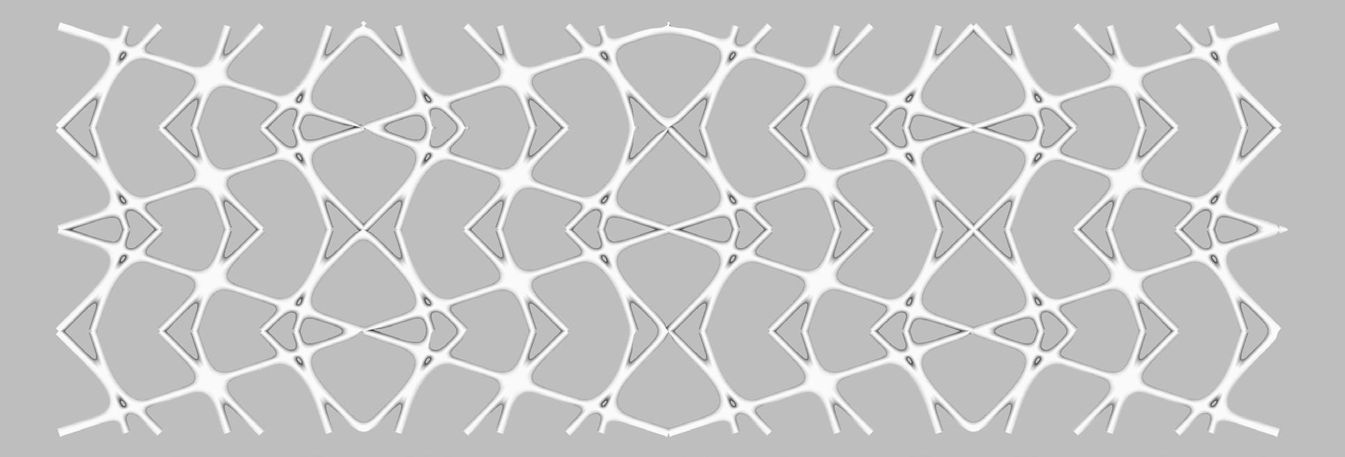
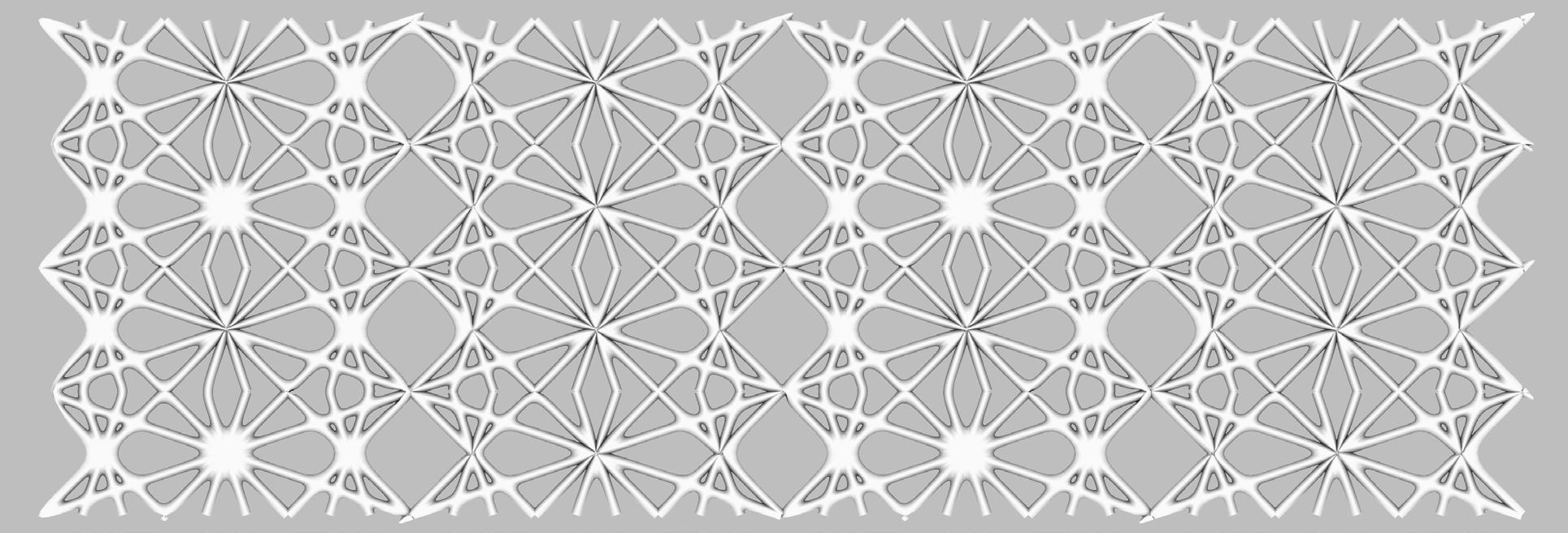
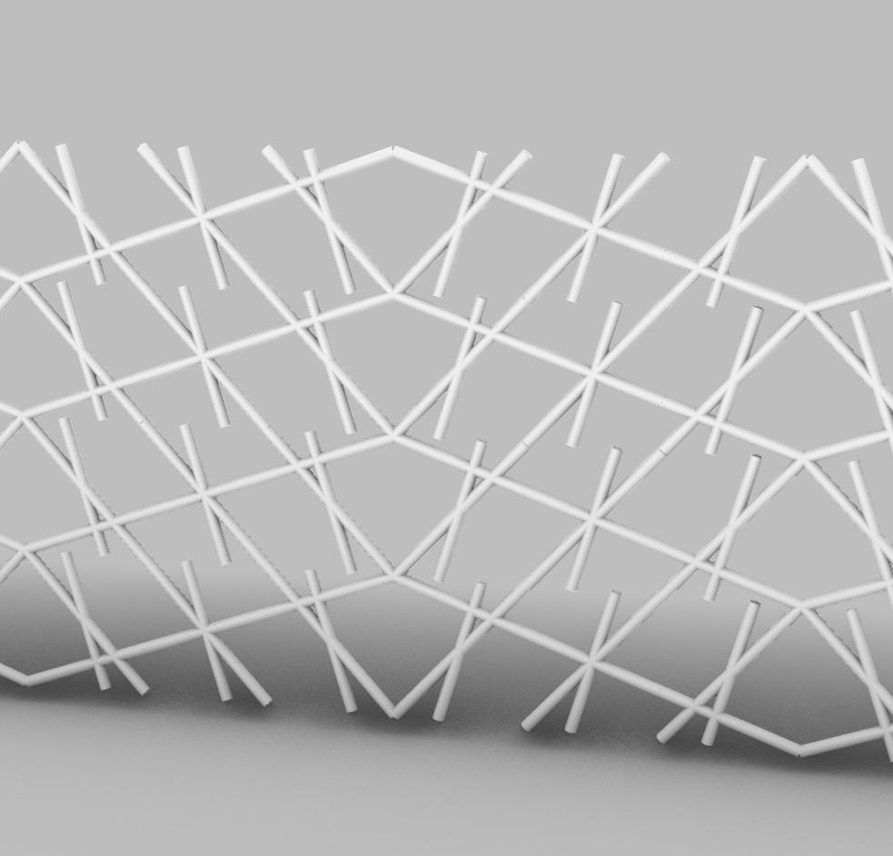
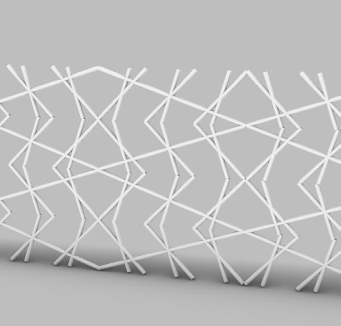
This series of images shows how the pattern up to date pattern was developed. Thinking of how this pattern structurally works and how it can transfer water are all considered here.

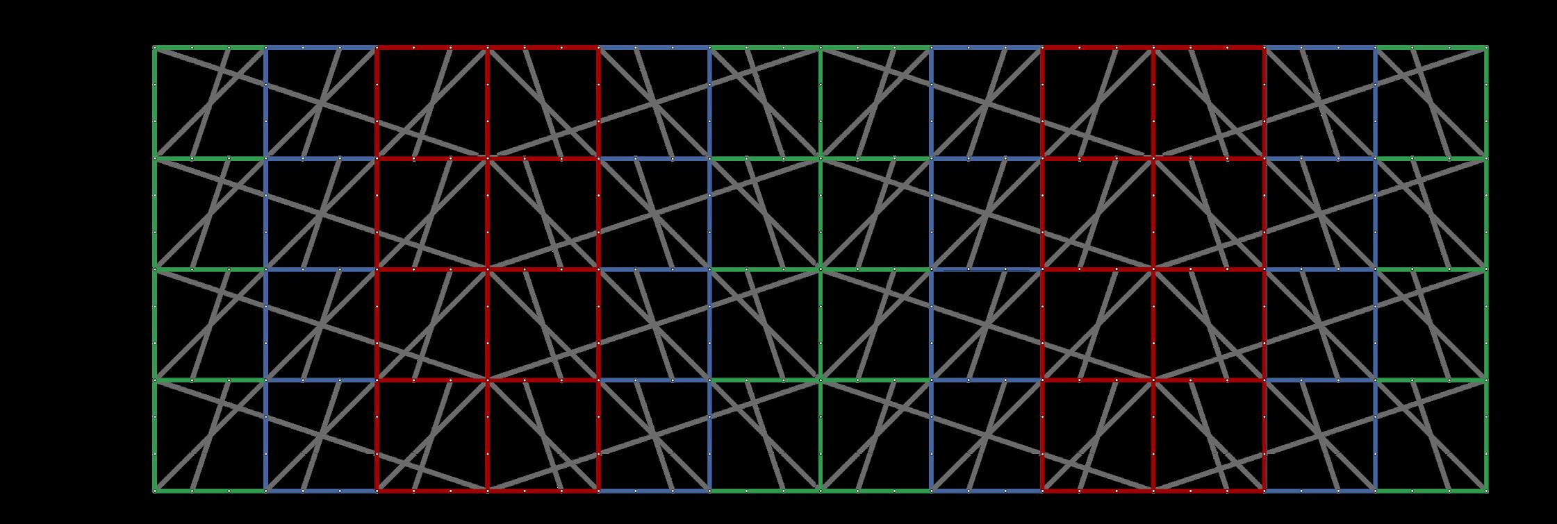

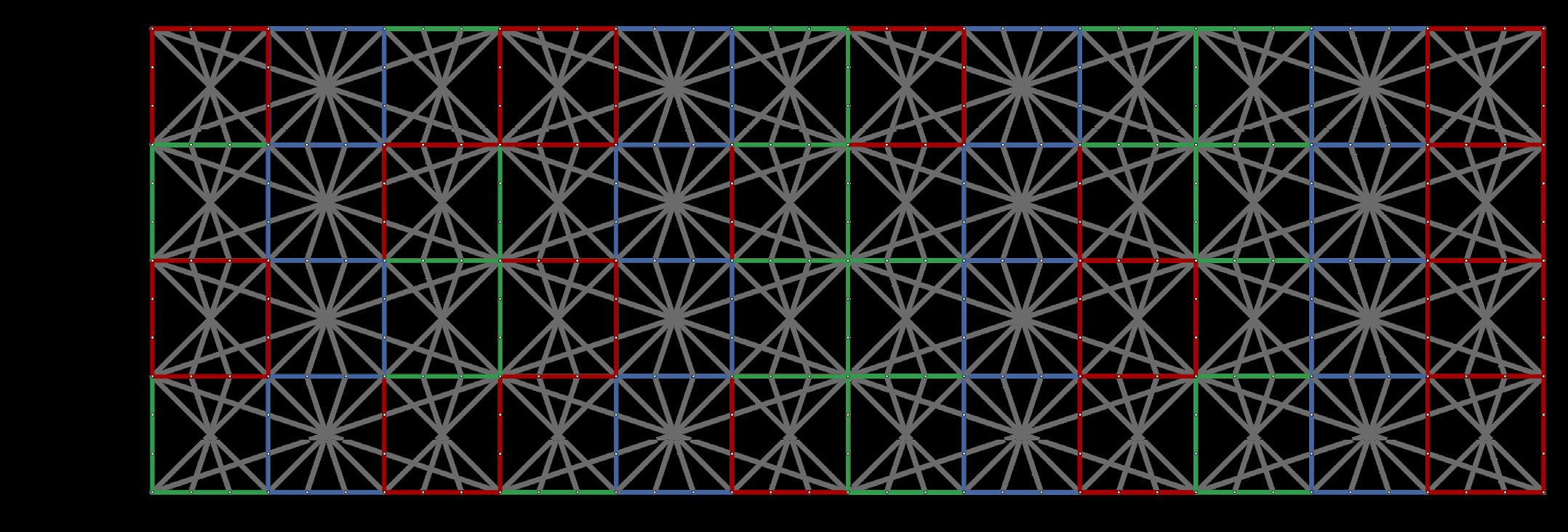
BLOCK A
BLOCK B
BLOCK C
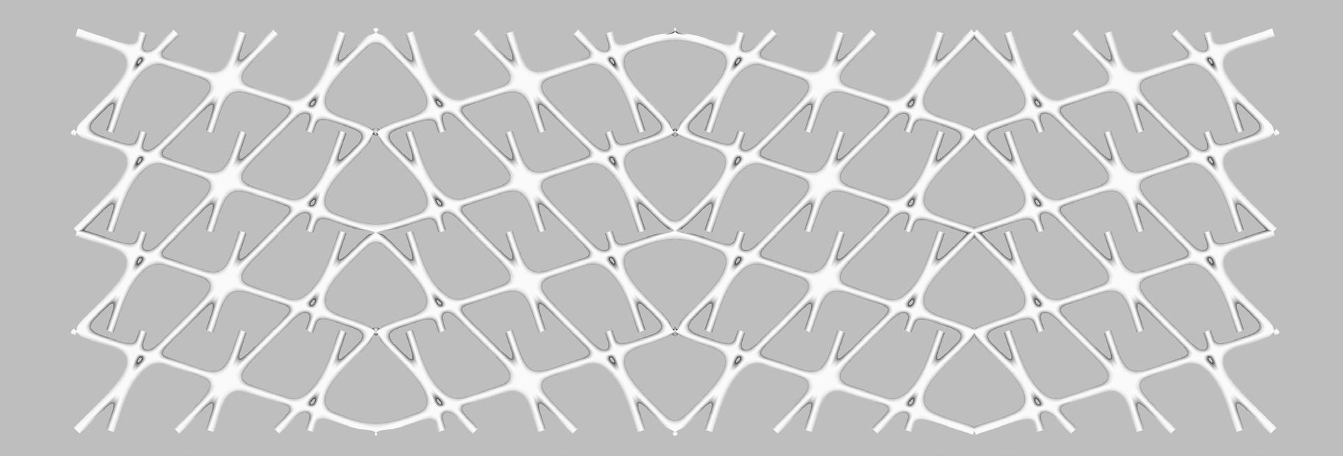
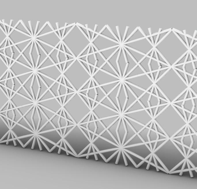
ADDING GEOMETRY
WATER FLOW ANALYSIS
When examining the geometry generated by the changing block pattern, I realized there would be difficulty getting water down this assortment of tubes especially if we were trying to minimize material and energy.
Therefore, the above piece was added on adjusting the geometry slightly to be able to funnel water efficiently.
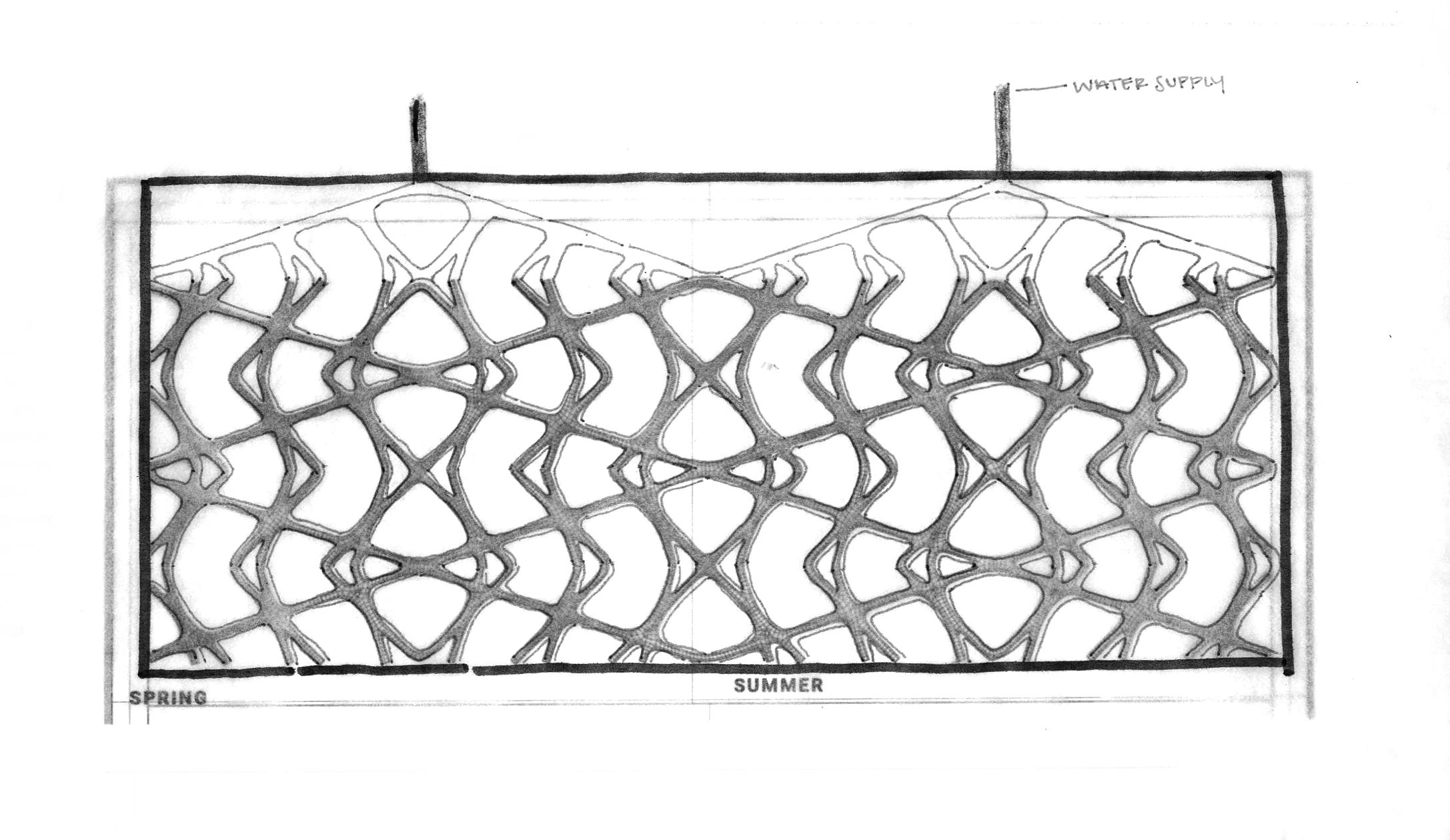
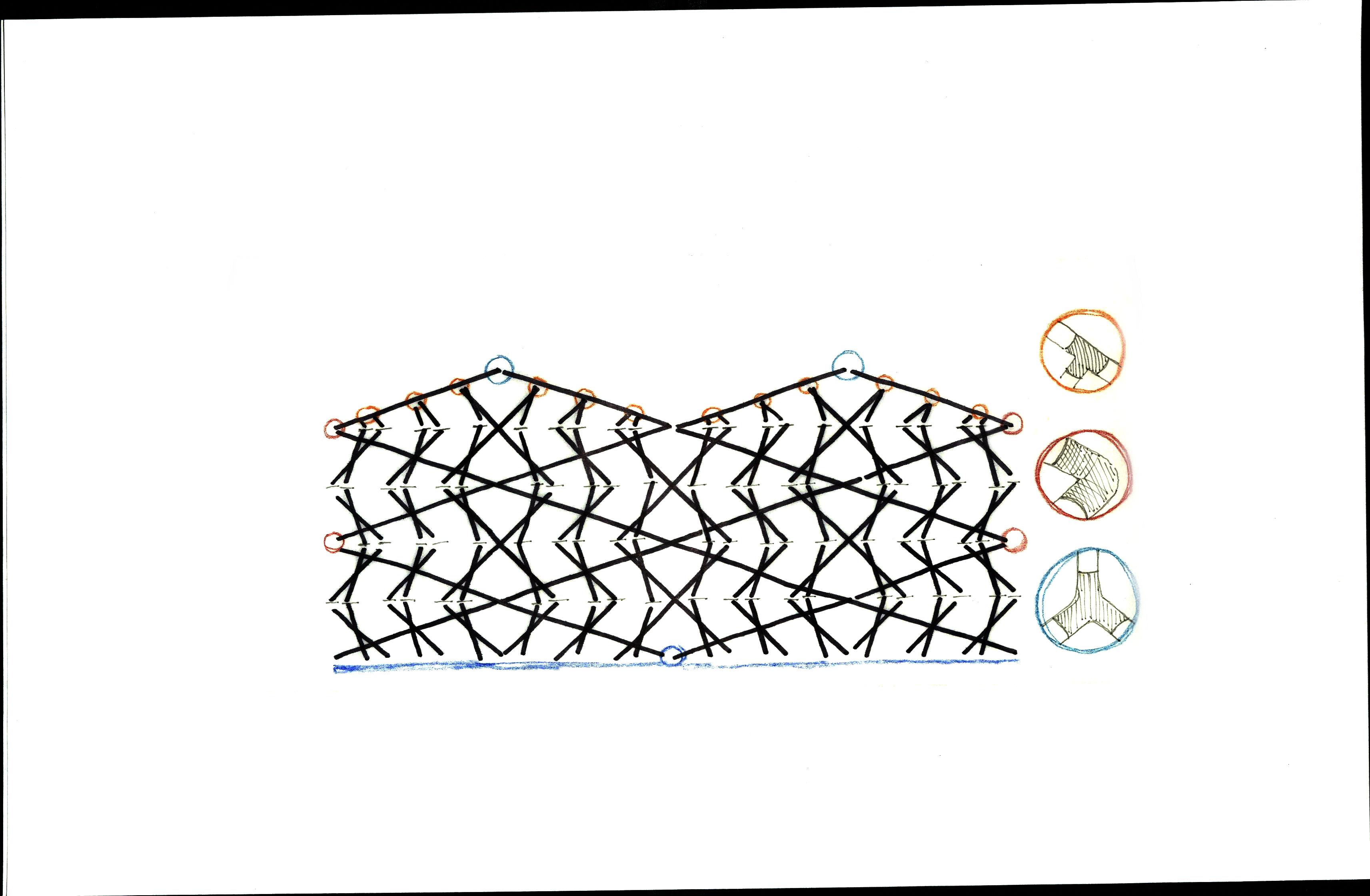
The diagram to the right shows my original connection analysis. Revealing we also wanted to minimize the amount of connections, I opted to use pex pipe in order to get the flexibility needed to only have connections where it was completely necessary. As seen in the diagram there are three different connection types.
ADDING GEOMETRY TO HELP WITH WATER FLOW
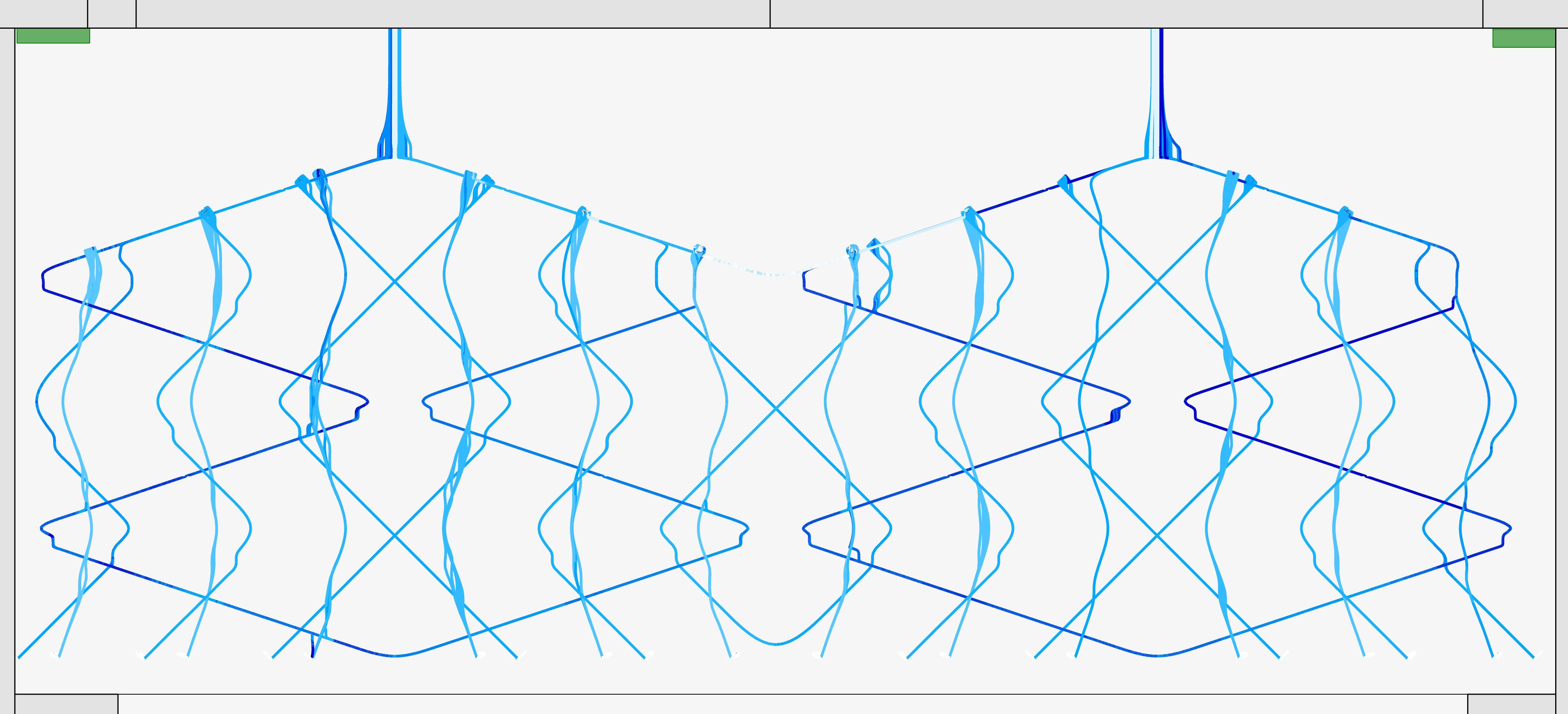
WATER CIRCULATION IMAGE:
PLANS & ELEVATIONS
MECHANICAL SYSTEMS
Here we start to dive into the technical drawings of the space. These were created along side the scale model to better understand the spaces we were working with.


READING ROOM | REFLECTED CEILING PLAN
Reflected Ceiling Plan
= 1'-0"
MECHANICAL SYSTEMS
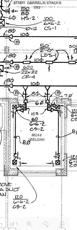
The axon and modeled mechanical systems help to start to understand what’s going on behind the ceiling. This information was retrieved from construction documents of Lawrence hall in the 90s.
To the right is the perfected pattern for the space in the space. The next thing I needed to figure out was how to tap into these electrical and water systems to promote life and growth in this space.
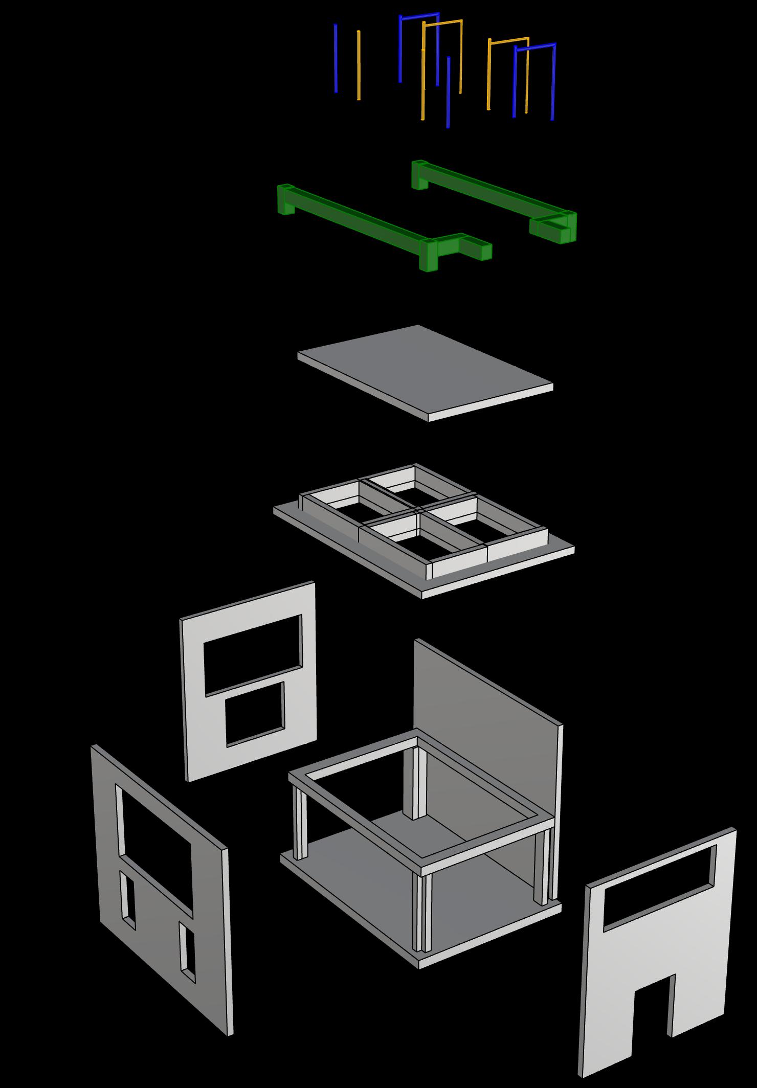
Acoustic Paneled Ceiling
Gridded Drop Ceiling
Wall of Study
Structure Entry Wall
IMAGE: LAWRENCE MECHANICAL SYSTEMS
DAYLIGHT EVALUATION
LIGHT EXPOSURE
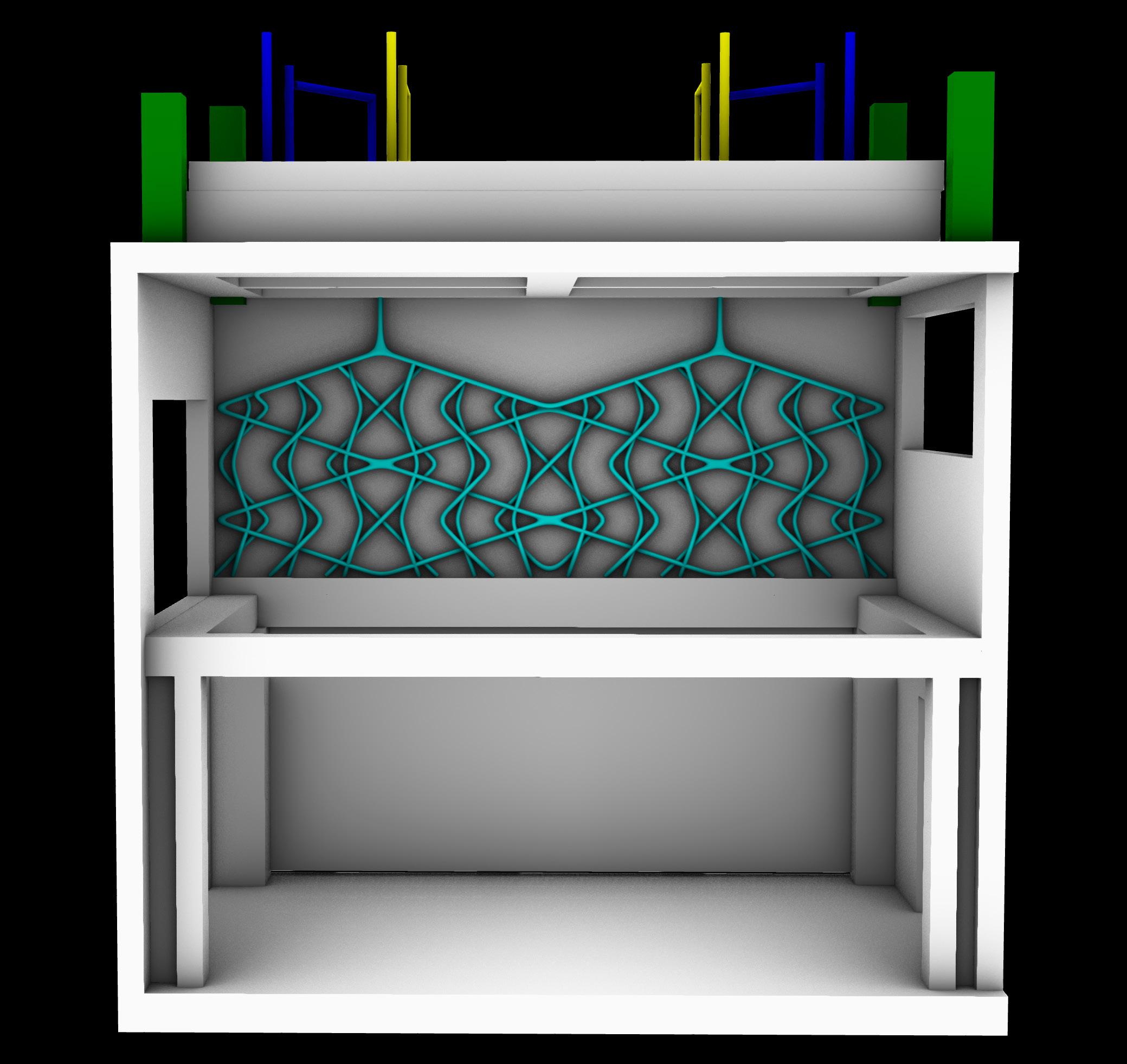
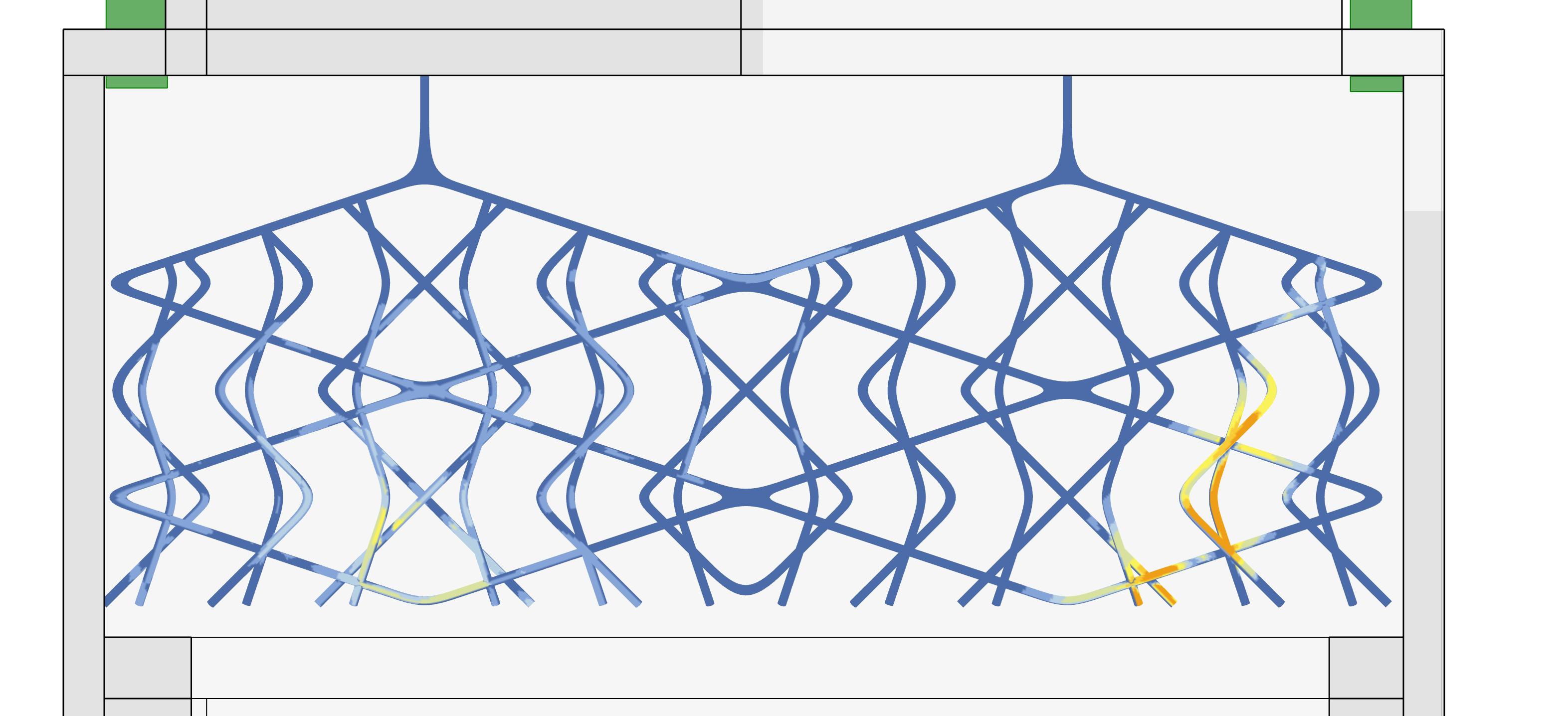
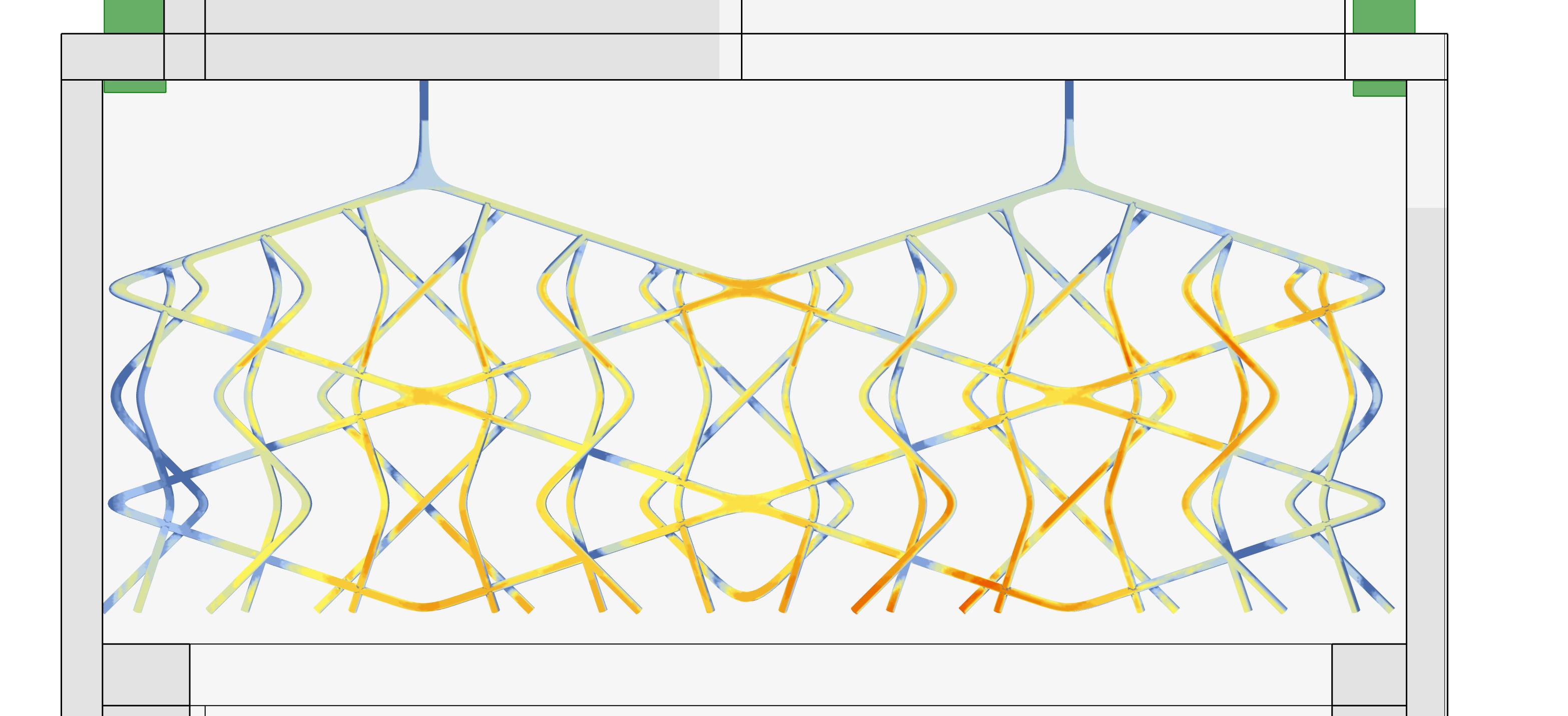
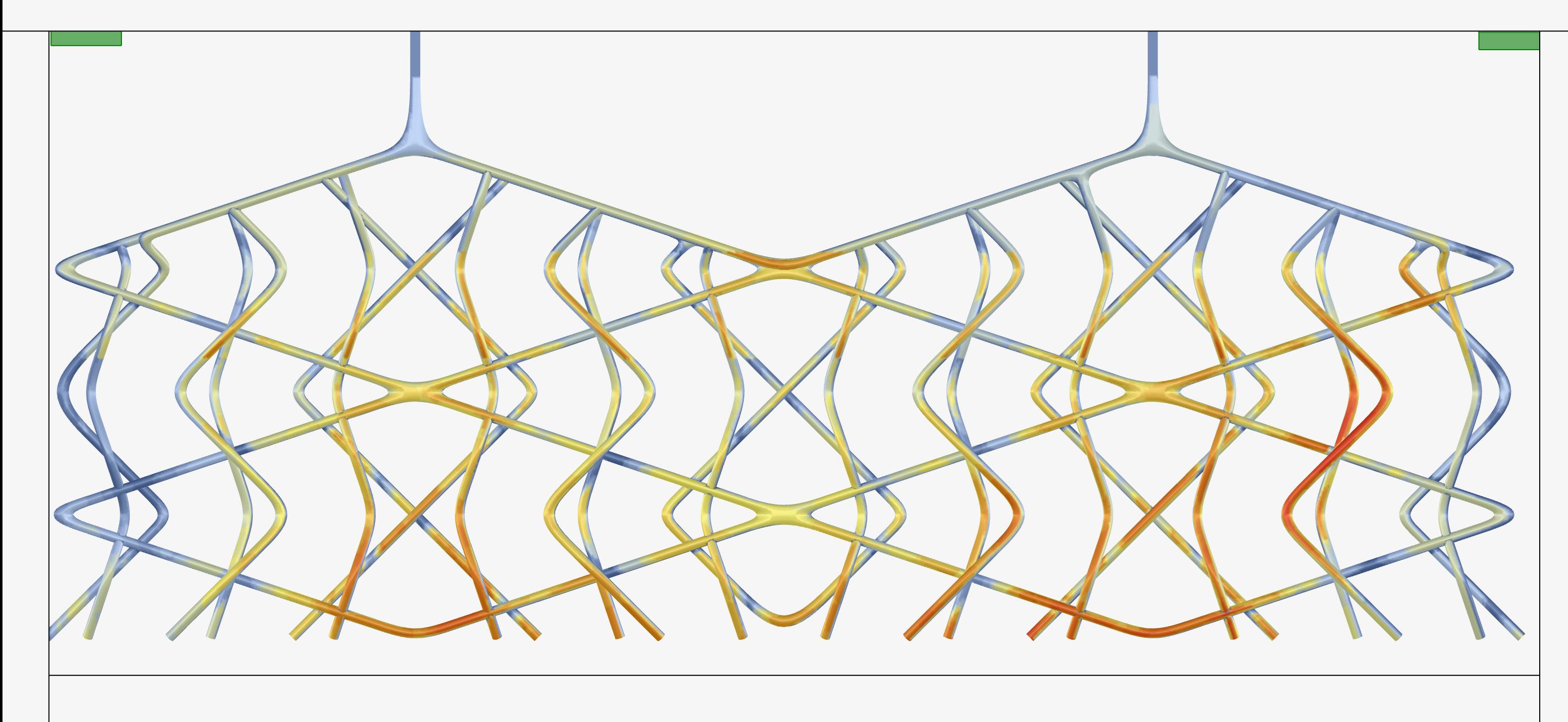
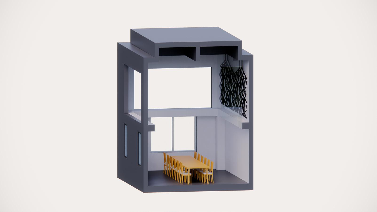
Thanks to grasshopper we were able to begin to analysis the light coming into the space. Here to the right there is an analysis first in the spring - summer and then below an analysis of the fall - winter sun. At first I was confused by the results. Why is there more exposure during the winter? And then I realized the placement of the windows to the south and that the wall space was in upper section of the room. The winter sun angle can reach further into the room than the summer sun .
YEAR ROUND AVERAGE
SUMMER SUN
LIVING SYSTEMS
PRECEDENT STUDIES
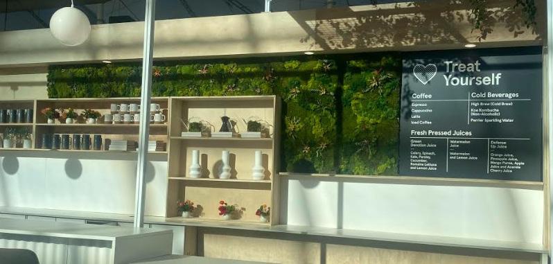
As I look into what plant to anchor into this space, a moss species was an obvious answer. The benefits of moss in a place are almost all positive. I began looking at how people have done this in the past, and I began to see that there are very few examples using specifically moss.
In conclusion, this will be a test run for if the plants will thrive in this environment.
“Green Wall Specification and Drawings.” Biotecture, 12 Sept. 2022, https:// www.biotecture.uk.com/design-andspecify/specifications-and-compliance/ specifications-and-drawings/.
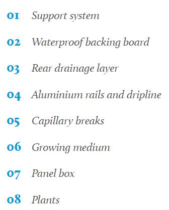
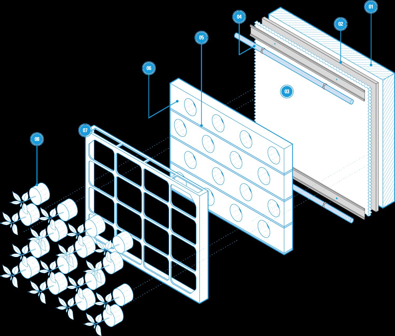
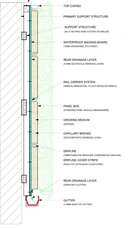
IMAGE:
“PROJECTS ARCHIVE.” VERTICAL GARDEN SOLUTIONS, HTTPS:// VERTICALGARDENSOLUTIONS.COM/ PORTFOLIO/.
LIVING SYSTEMS
POSSIBLE SPECIES
The benefits of moss in a space incredibly positive. See to the right some of those benefits.
Most mosses thrive in 3000 LUX spaces. This being said I’ll need to add some track lighting to the space.
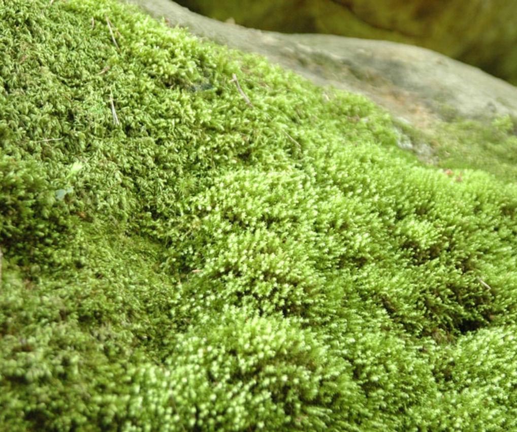

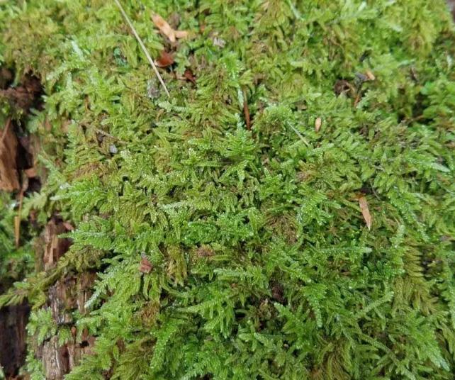
Thrives in the shade, so would be better placed at the upper edges of the wall.
Absorbs CO2 and helps to produce oxygen.
Usually needs regular watering 2x a week.
Absorbs CO2 and helps to produce oxygen.
Does best out of direct sunlight and should be kept moist. This moss was choses with the others because of its differing color and texture.
This is a Sun Tolerant Moss, so it can be placed in some of the more exposed places on the wall.
The moss naturally grows in dense light green mats on rocks, rotten wood, or peaty soil.
Absorbs CO2 and helps to produce oxygen.
SHEET MOSS
PILLOW MOSS
FEATHER MOSS
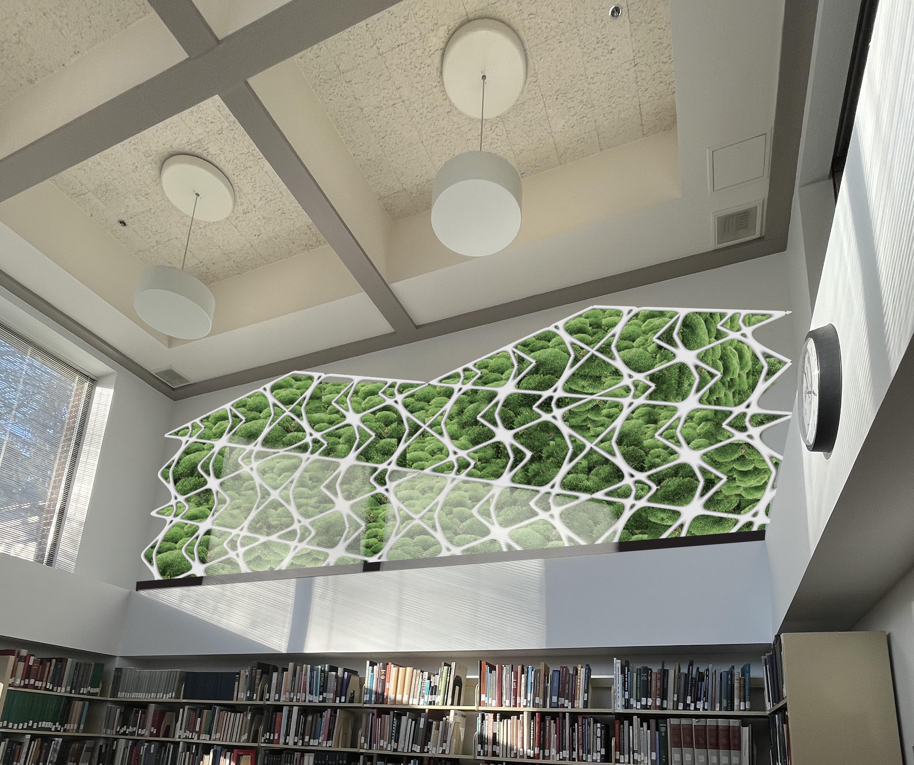
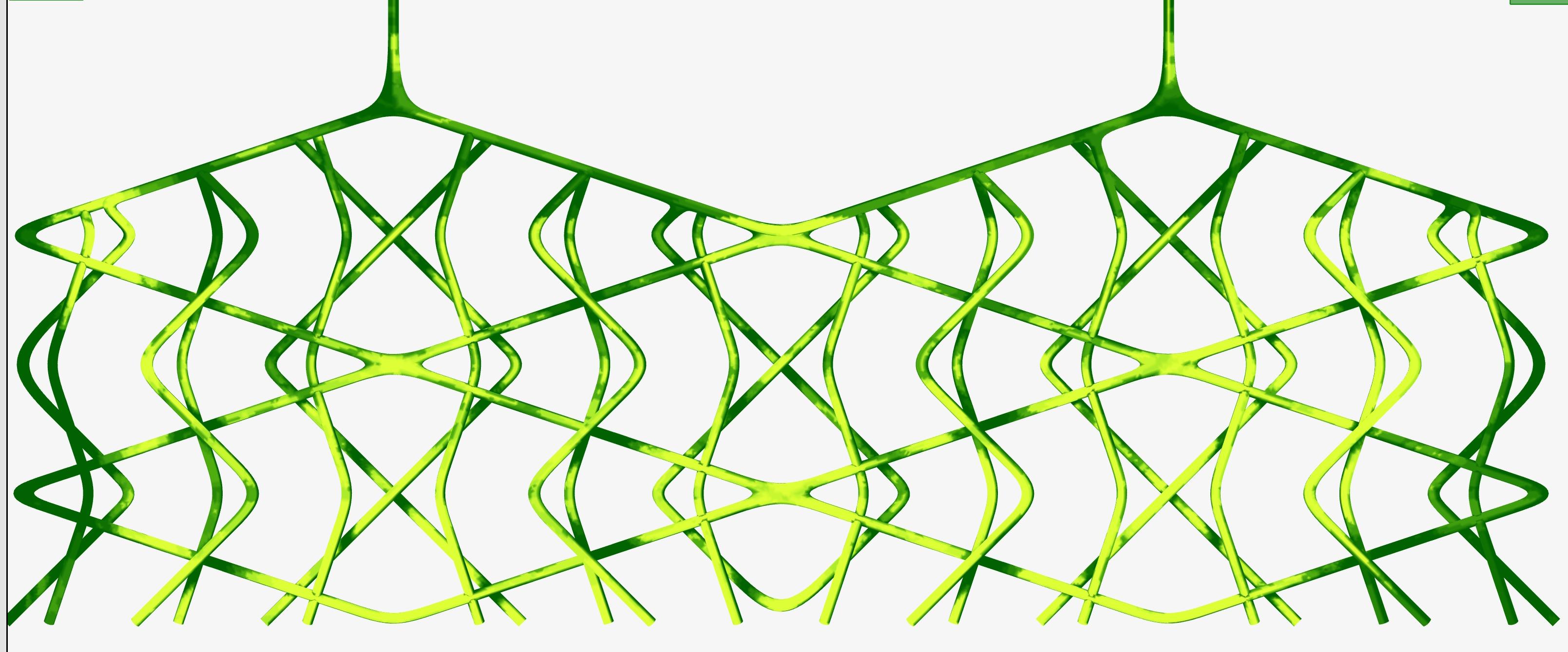
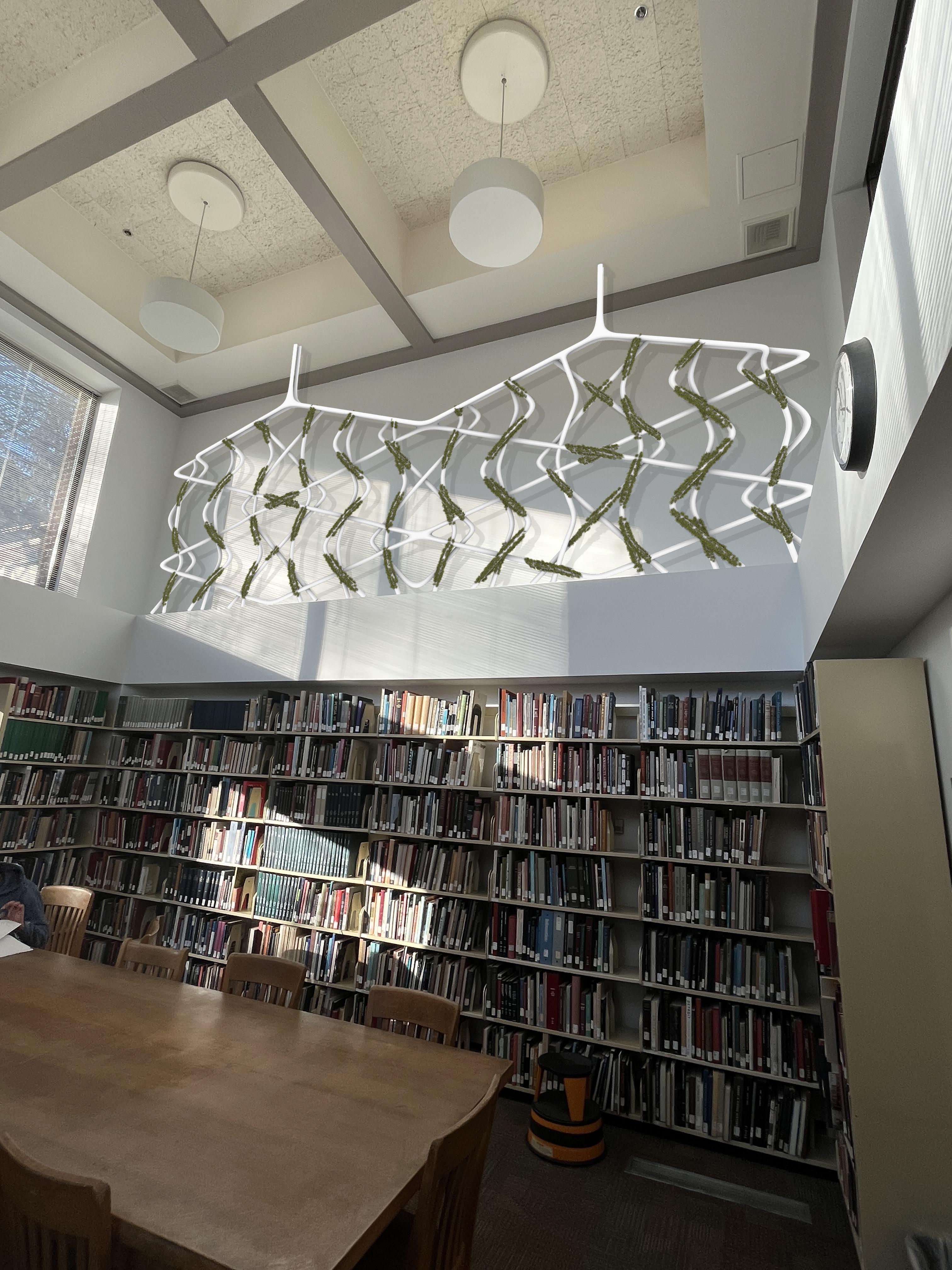
IMAGE: RENDER OF WALL IN READING ROOM
This was my closing render for my midterm. From here, I strongly reconsidered the placement of the moss as the placement between the PVC system might create issues with irrigation.
This being said, when I move forward from this point I begin prototyping how moss can grow with in the PVC irrigation system.
PROTOTYPES
PART 2
PLANTING TECHNIQUES
PERFORATING PVC
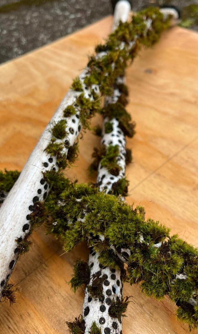
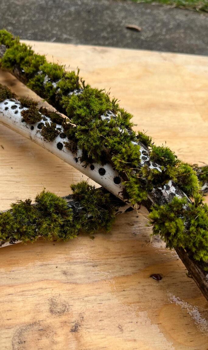
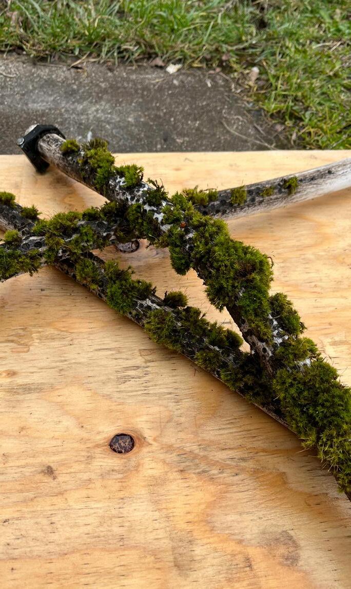
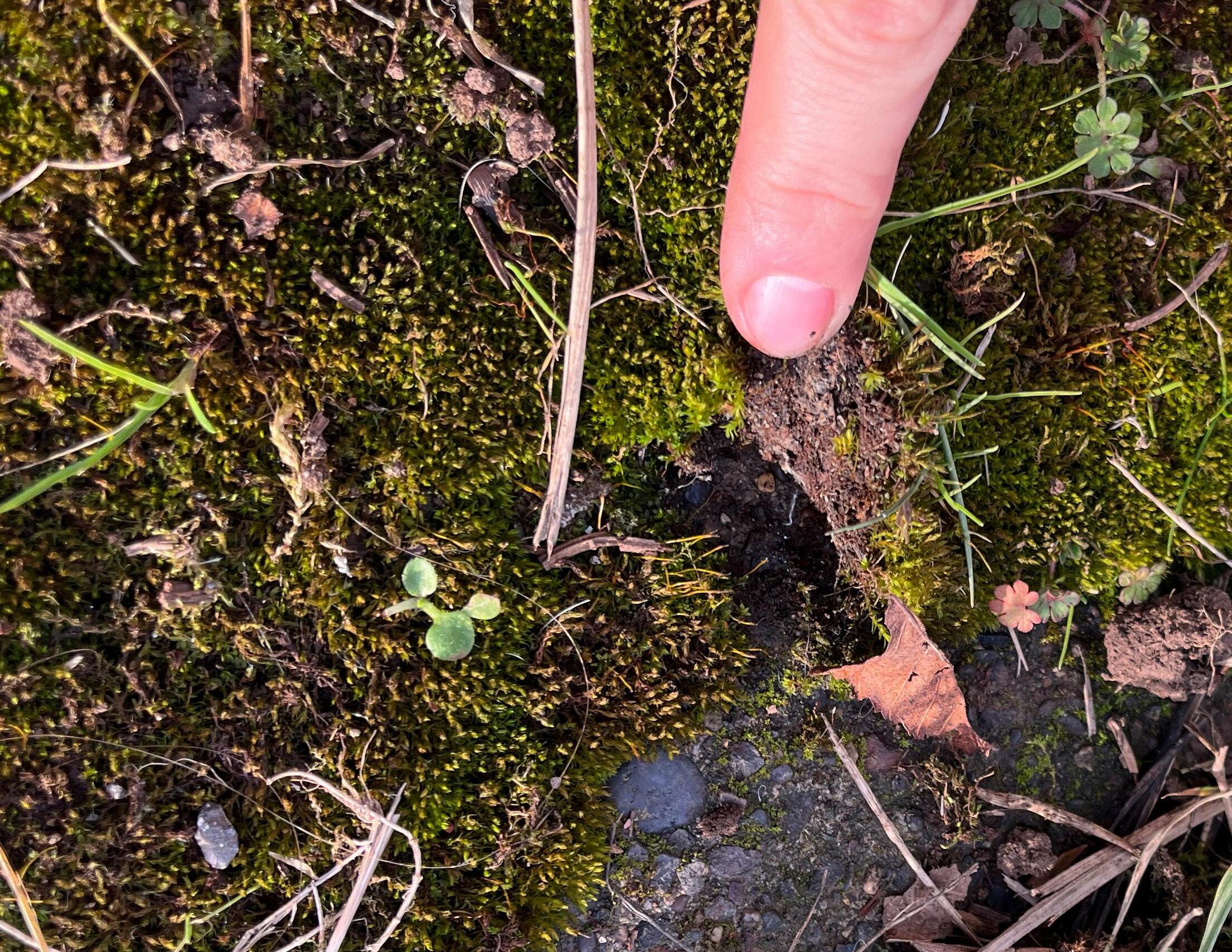
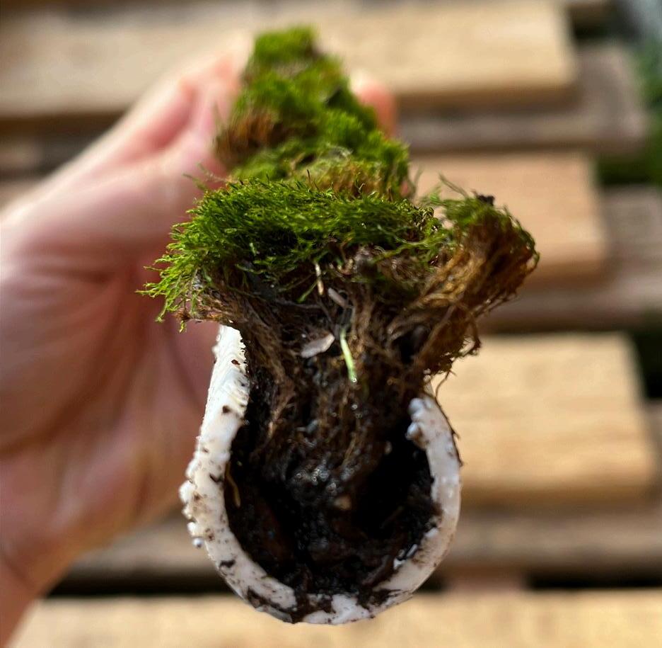
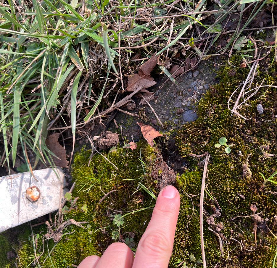
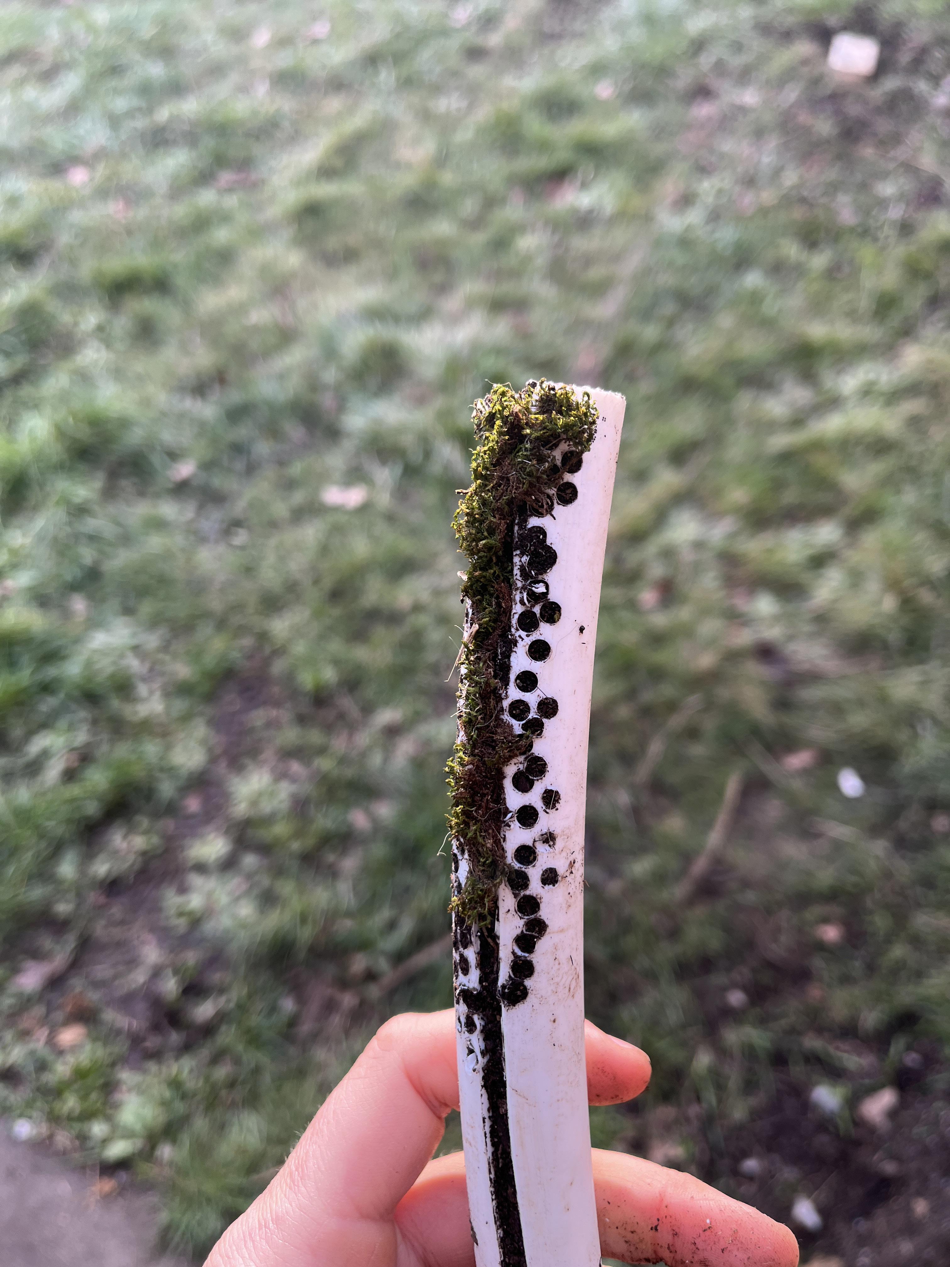
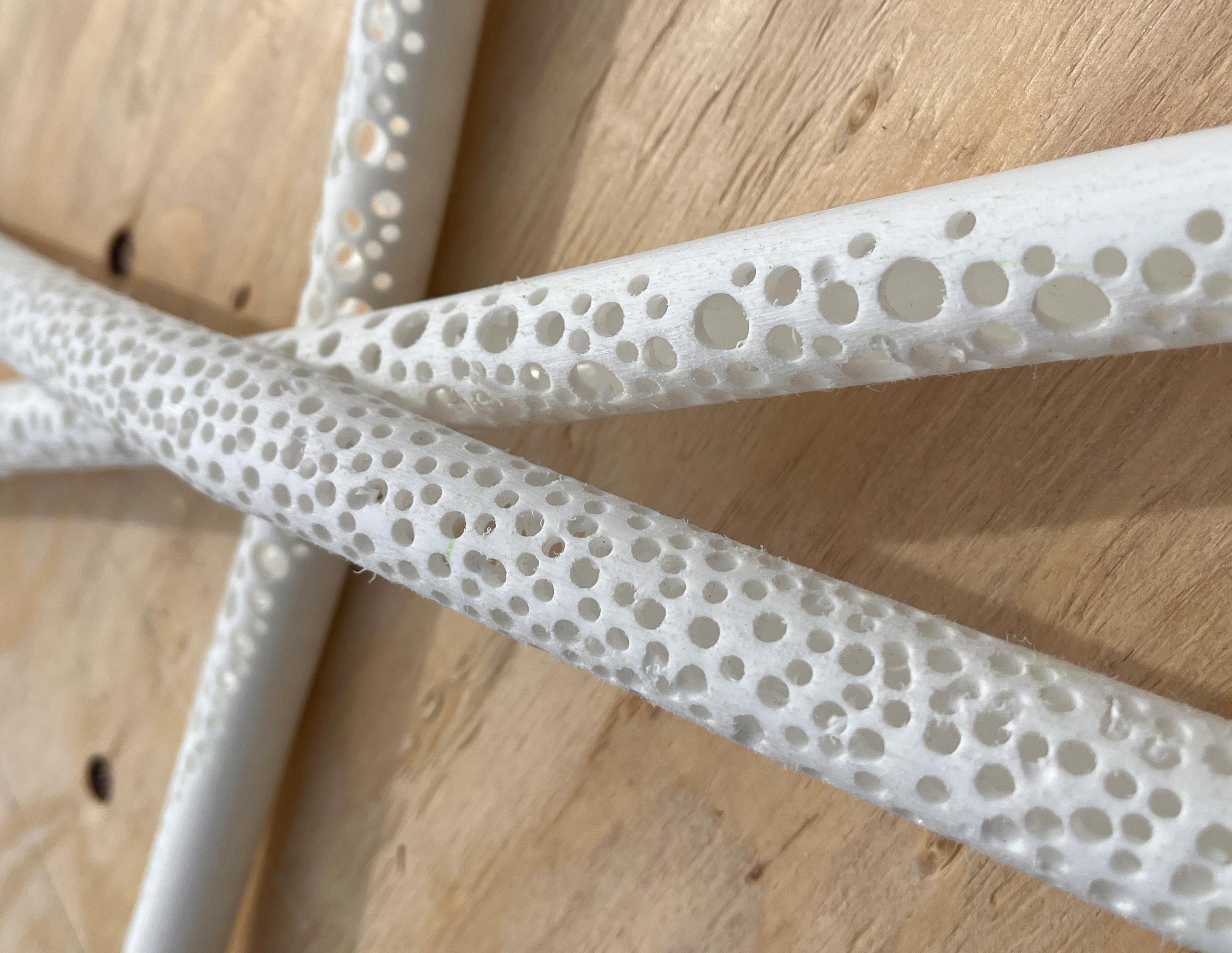
I began to experiment with the PVC after mid term. How could moss grow best in this environment? How can I help it completely take over the space?
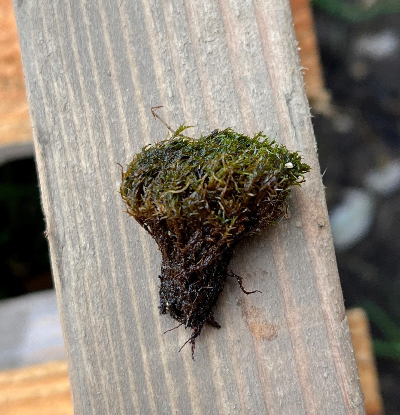
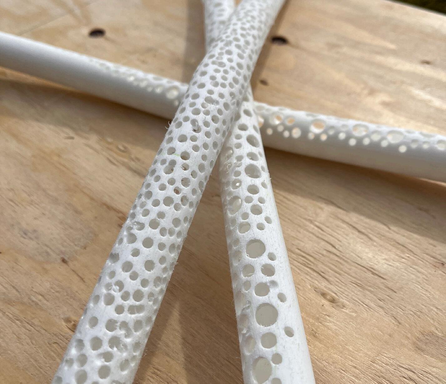
I decided to go with the circular perforations in the tubes. As you can see on the far right the rhizoids of this pillow moss came to a point and could fit in a much smaller perforation and then blossom out to be about to maximize Photosynthesis.
PROPAGATING PILLOW MOSS
PROPAGATING PILLOW MOSS
HARVEST SAMPLE
CAPILLARY ACTION
How moss is able to absorb nutrients through the water it collects
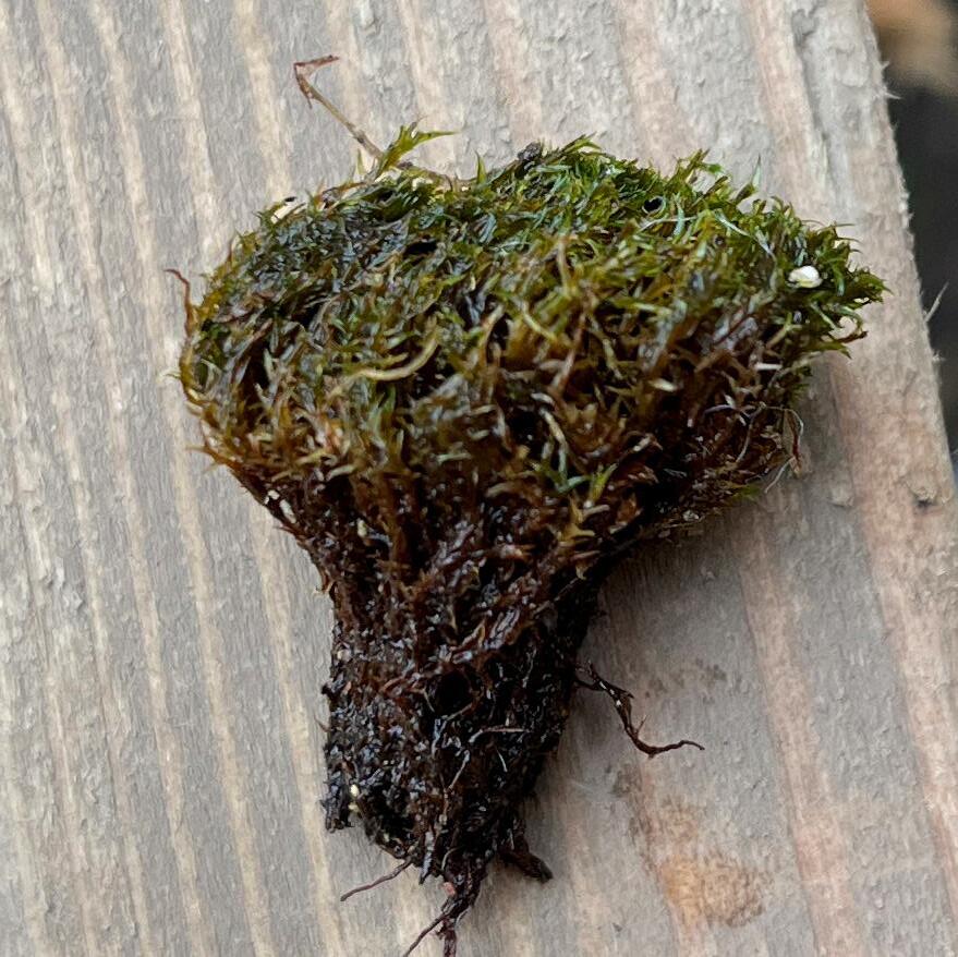
IMAGE: Moss Anatomy Diagram

RHIZOIDS
GAMETOPHYTE
FULL SCALE MOCKUP
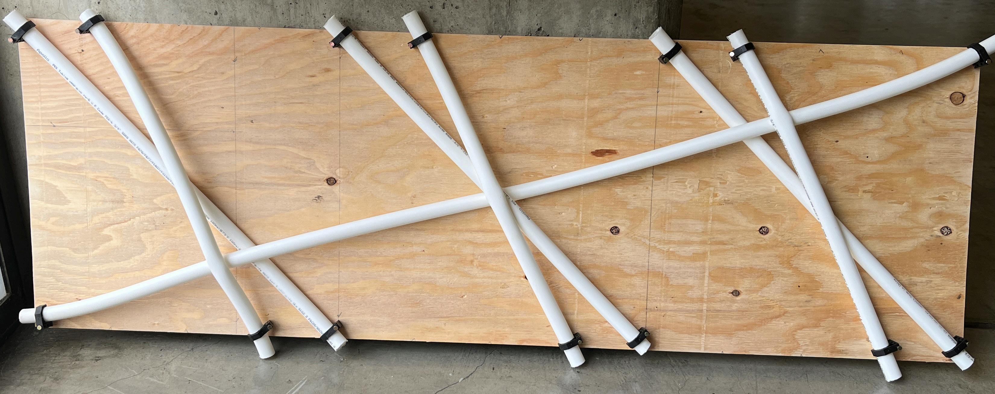
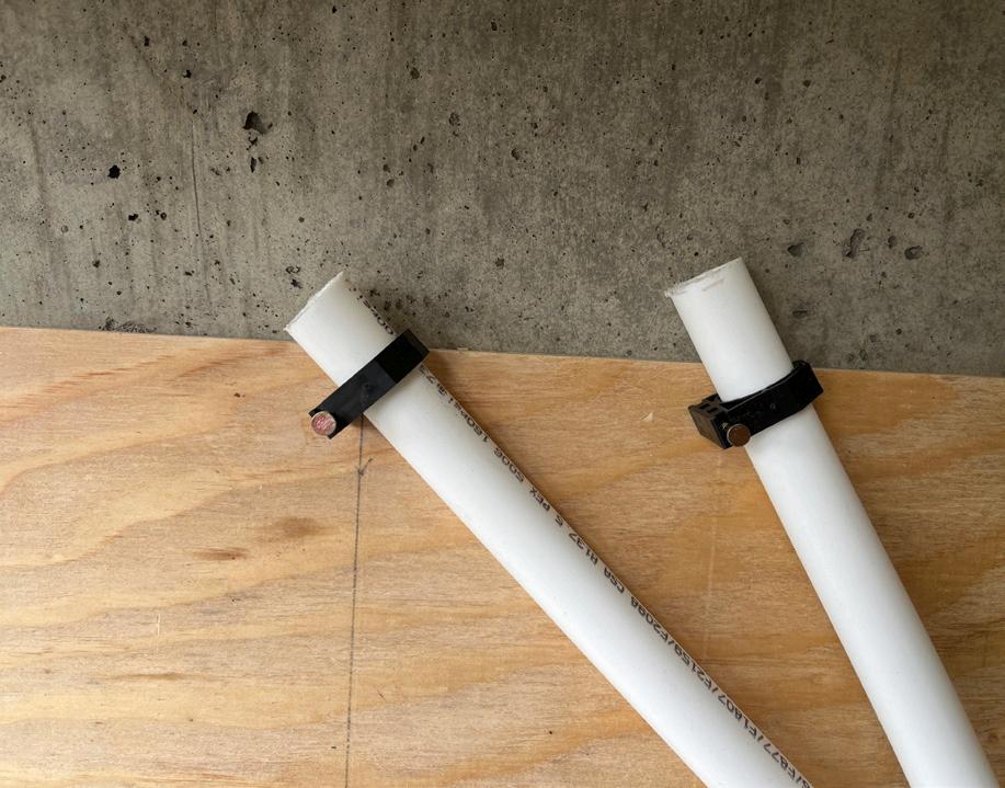
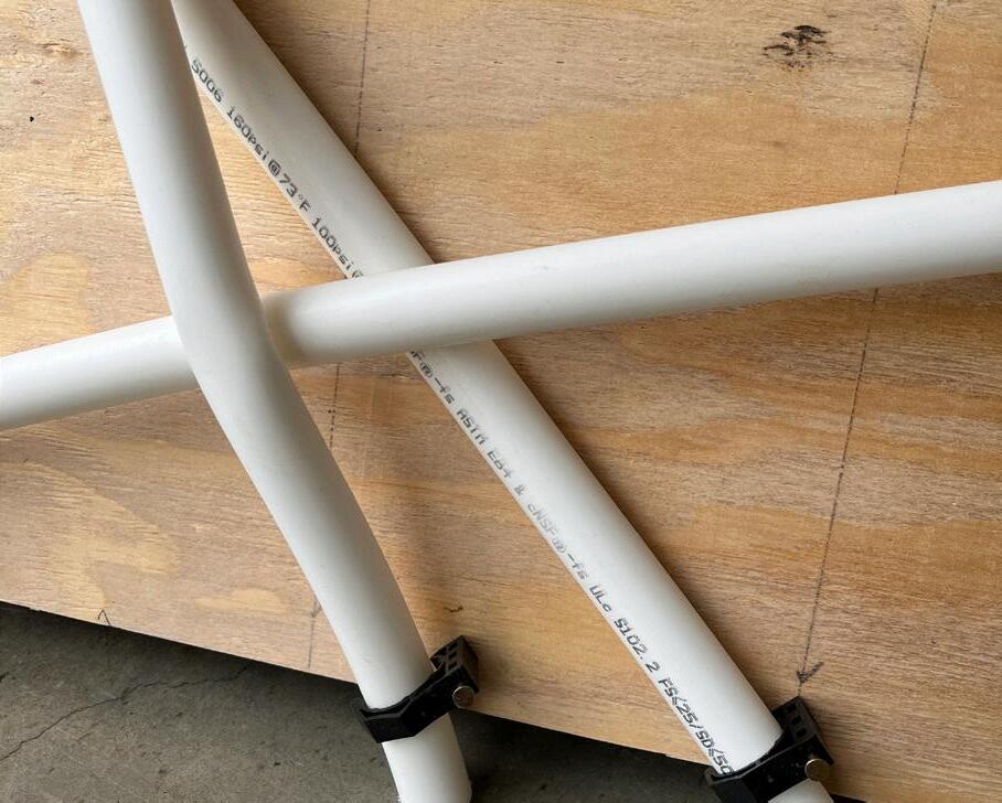
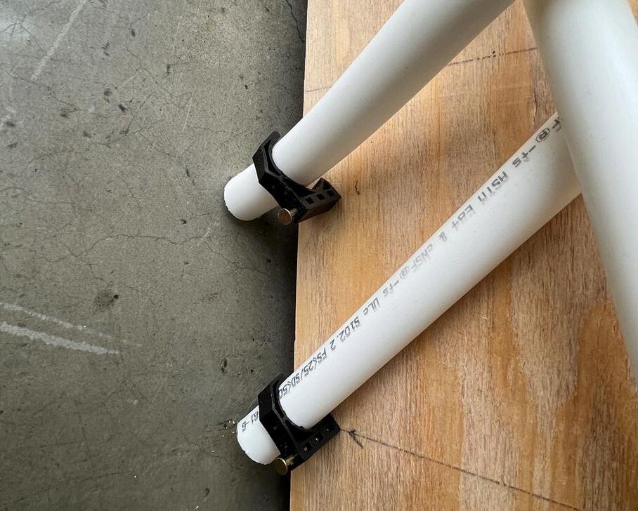
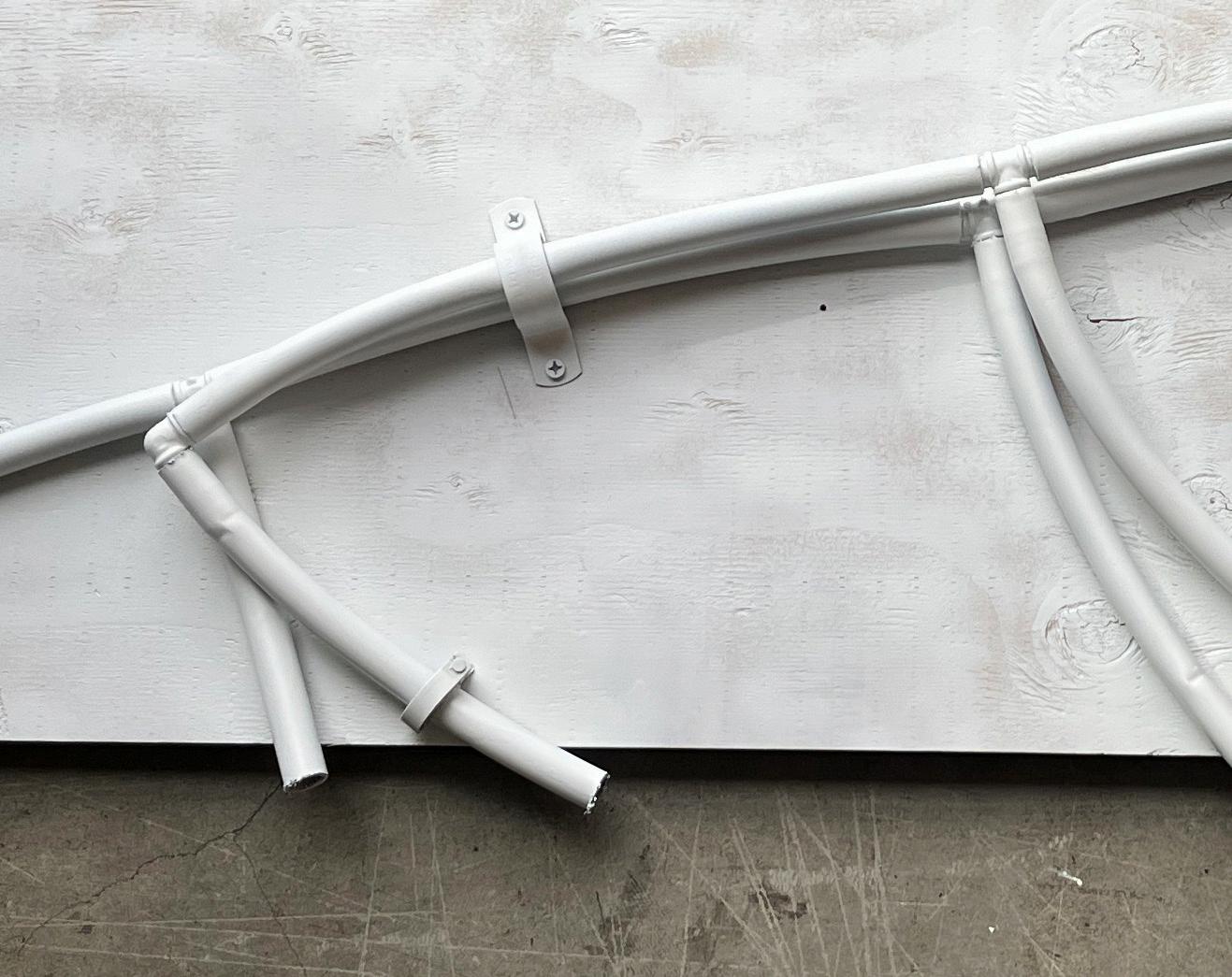
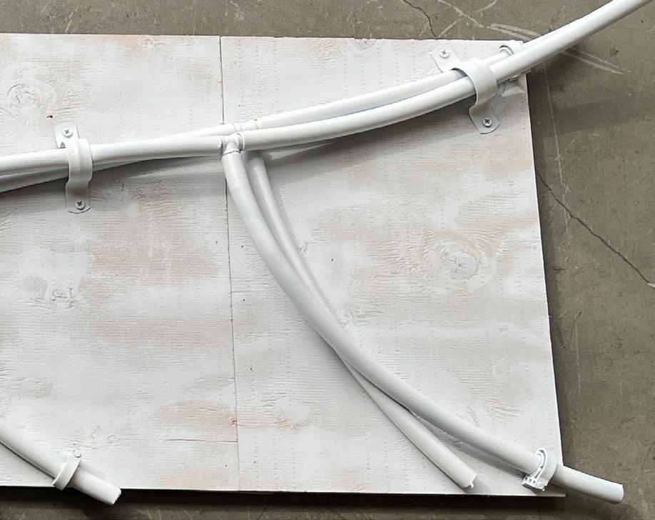
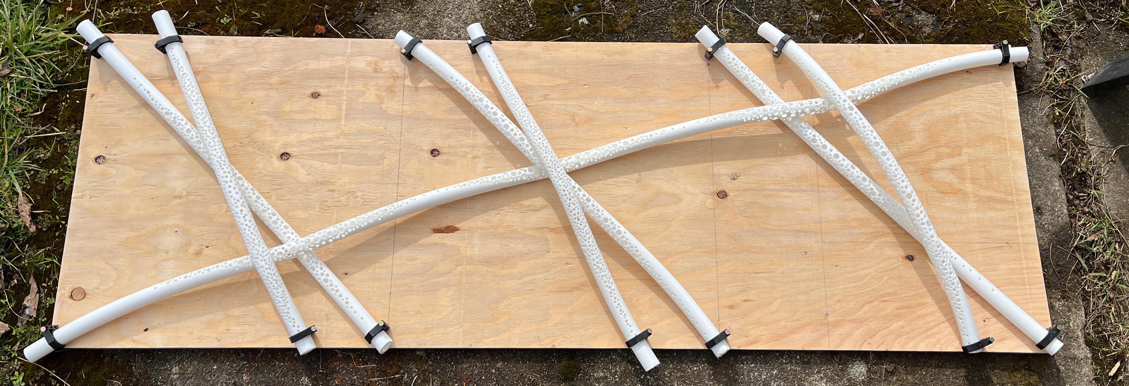
The one to one scale model started to show me how this would actually work in the 3rd dimension. I saw how these pipes would begin to overlap and how we could actually distribute water across the wall. There needed to be adjustments make to the over all shape because of drainage. On the lower right hand side of this page there is a water flow analysis of where water would drain if the pattern was a 2 dimensional lattice. More research needs to be done in order to understand the weaving lattice water flow.

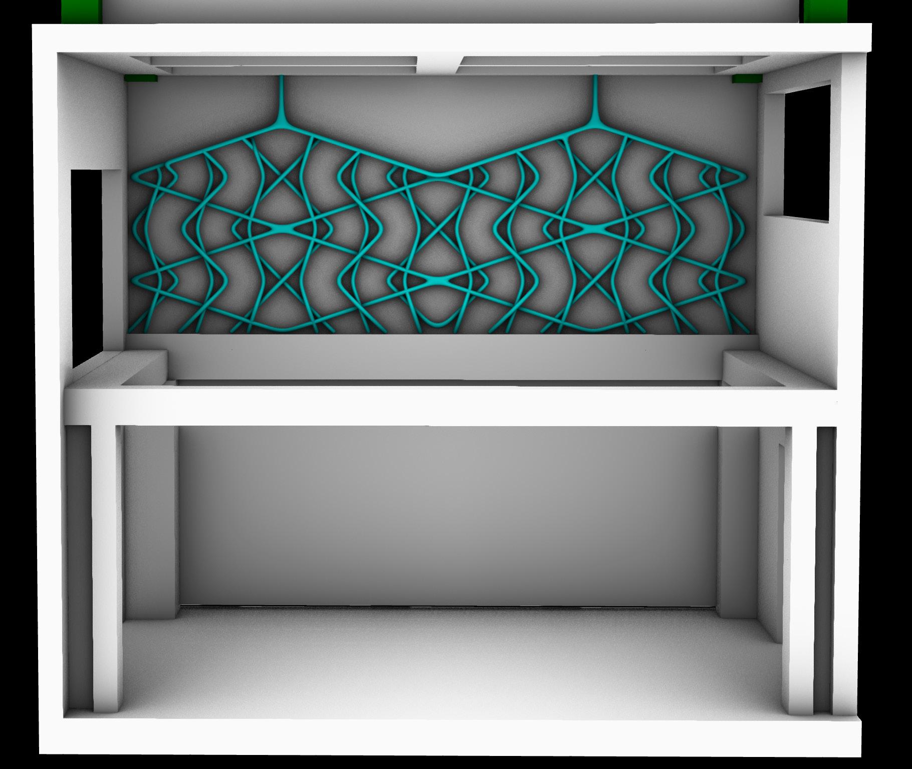
IMAGE: Caption Caption
54”
18”
FULL SCALE MOCKUP
SCALE 1’ : 1’
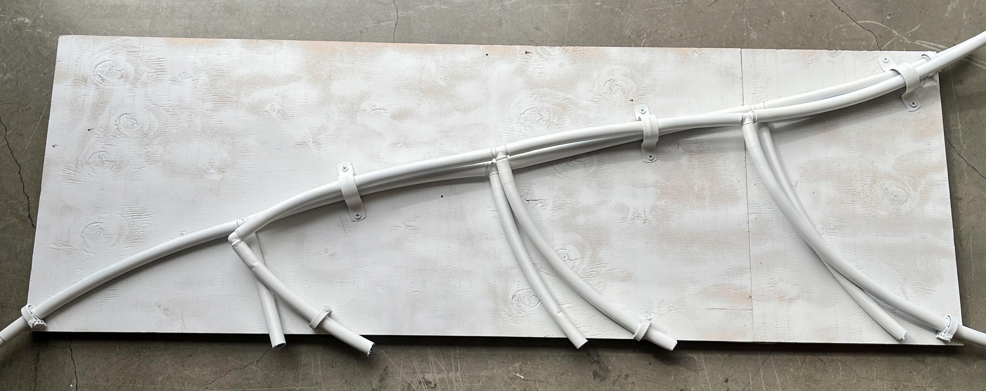
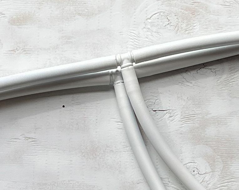
This 1:1 mockup helped me understand the upper connection of the piece. The top part of this installation is the most complex as it has all the connections and were many failures could occur. I used irrigation line and connection joints in order to connect these pex pipes efficiently and minimally.


IMAGE: Caption Caption
54”
18”
FINAL DESIGNS
PART 3
THREE DIMENSIONAL REPRESENTATION
VR | 3D PRINT | MATERIAL
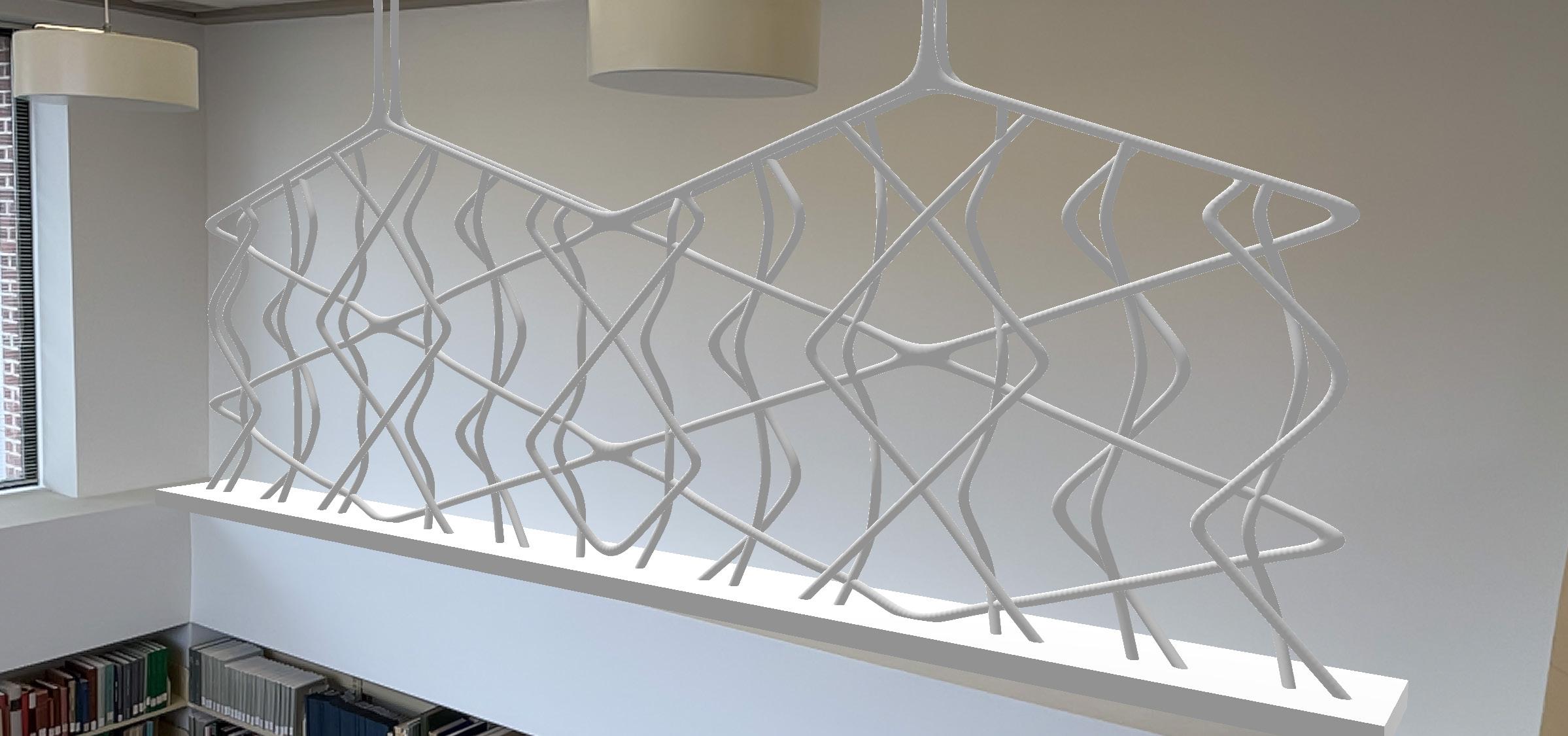
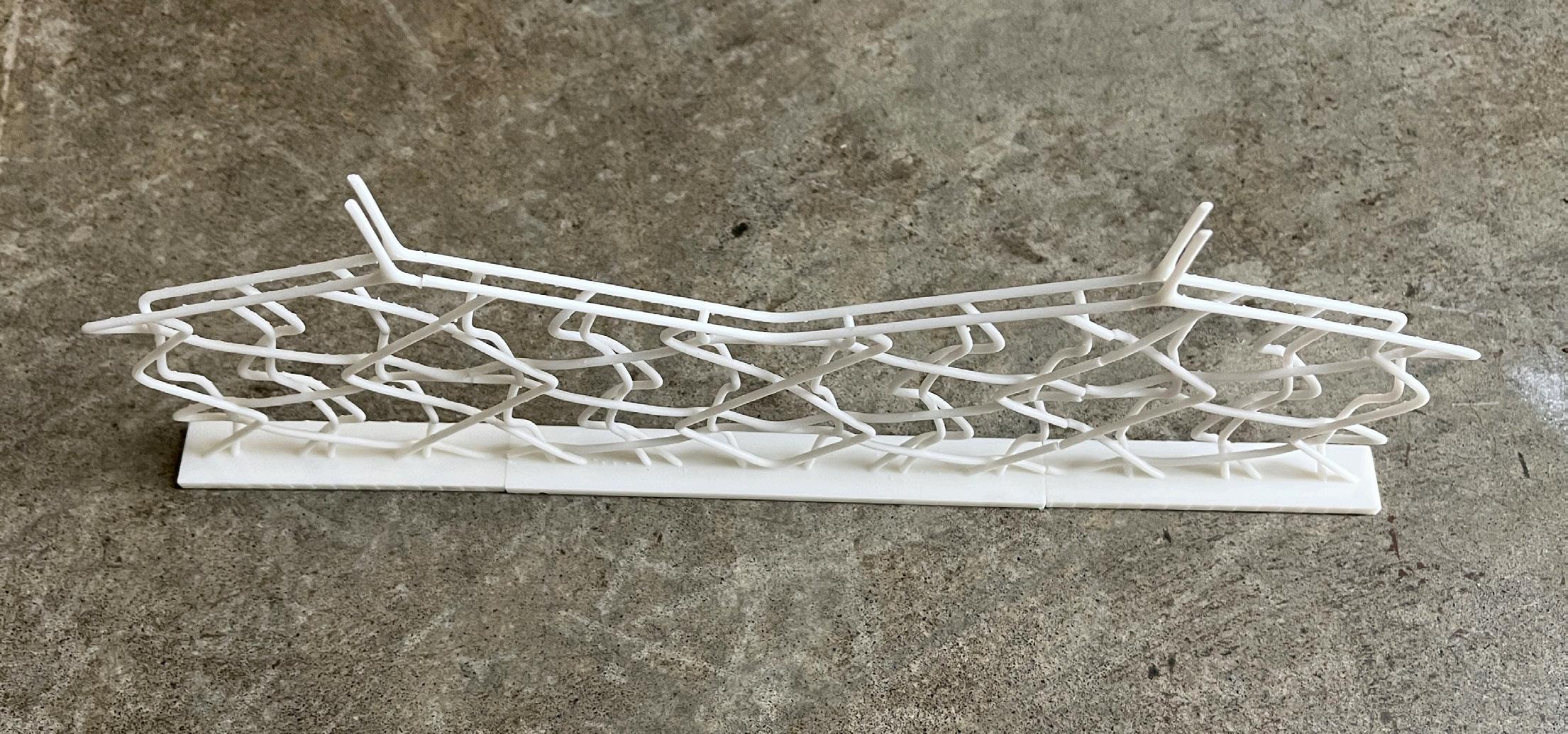
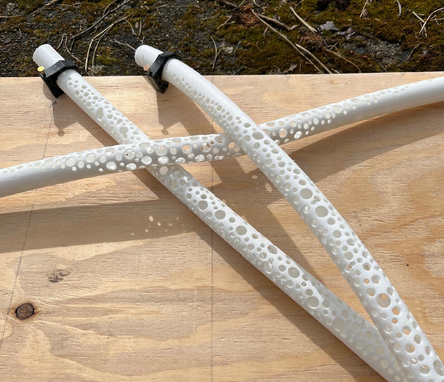
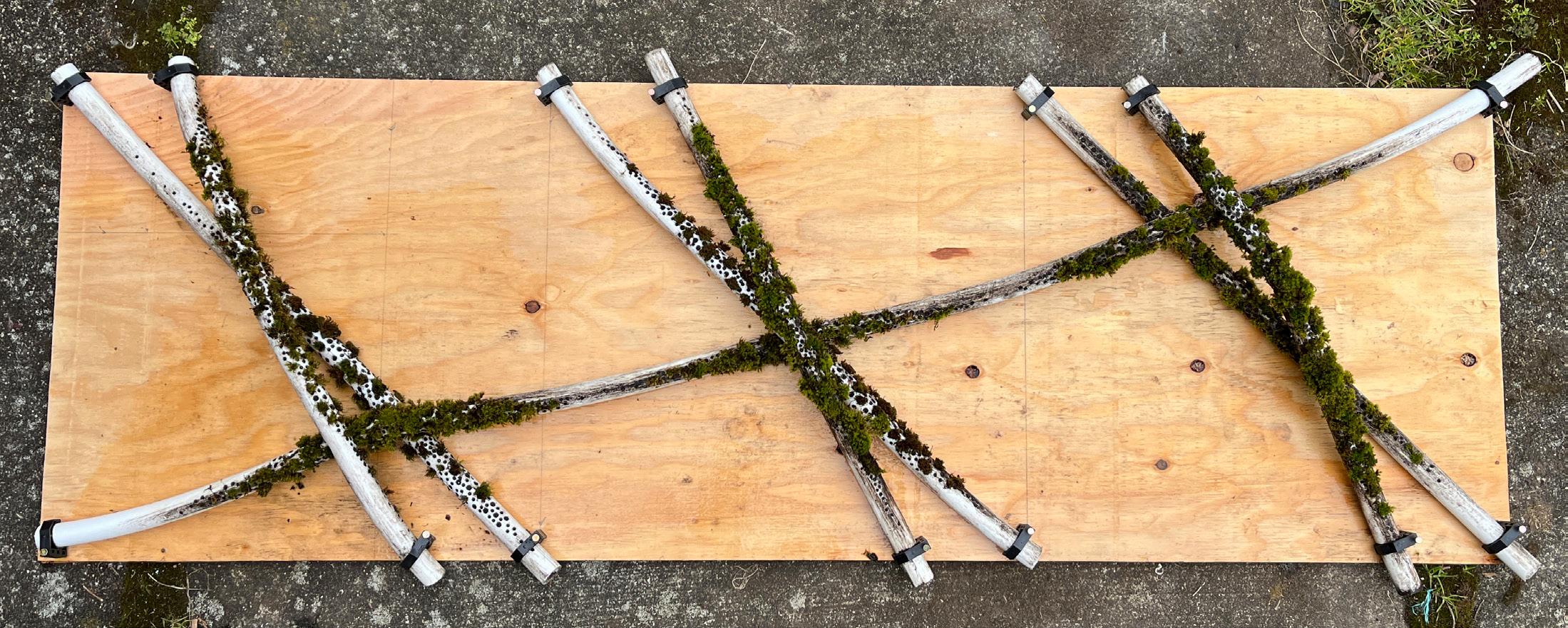
The final design came down to a gradient of perforations in the pipes. This would encourage growth, but also allow for the pipe to be seen in the installation and not be fully overgrown.
To the right is my 3D Print at half scale and my VR model in the space. It was exciting to explore some new ways to experience these designs.
TECHNICAL DRAWINGS
LIVING WALL SECTION
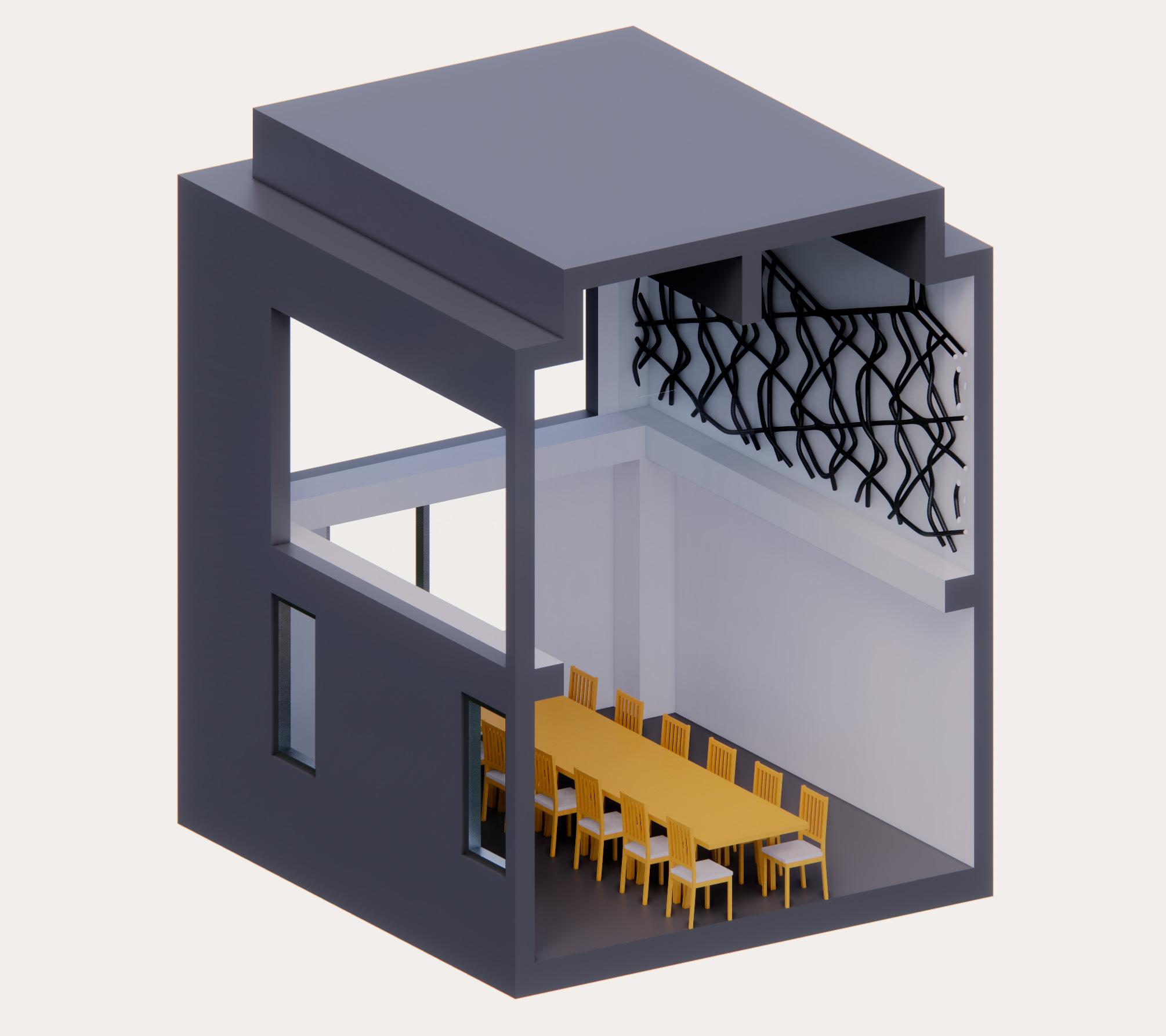
Thinking about how to install this green wall into the space I decided it would be best to put blocking between the existing studs to be able to freely support the tubes. This piece would also do best almost floating in space, so I’ll use a metal sub structure that will be mounted about 3 inches off the wall to attach the pex tubes too.
Moss is a moisture rich plant, and I am installing these species in a library. Some would say the two don’t mix, but I believe that this is an opportunity to create a living wall and better the space entirely.
There will be glass installed to mitigate the moisture entering the room, but because the HVAC system is located directly above the installation there will be a vent to allow fresh air to circulate.
AXON VIEW OF SECTION
HVAC Supply air
Vent in glass to allow air to flow
DIAGRAM OF MECHANICAL SYSTEMS TECHNICAL DRAWING
IMAGE:
Technical Drawings | Wall Sections
Taping into existing water lines for irrigation
Existing ceiling structure to remain
Existing Wall Header
Proposed green wall design
Pipes filled with damp soil
Metal backing to suport free flowing pipes filled with damp soil
Blocking to support substructure on existing studs
1/2" GYP water resistant
1/2" Glass to contain humidity
Basin to collect and drain exess water
Existing framing to hold drainage
ARCHITECTURAL ORIENTATION
AXON VIEWS
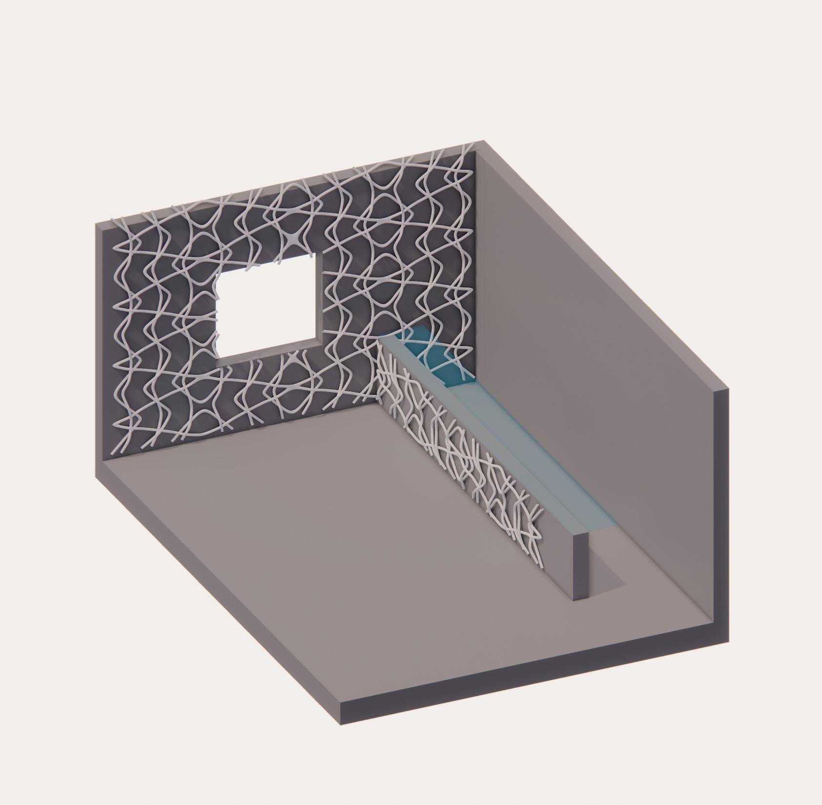
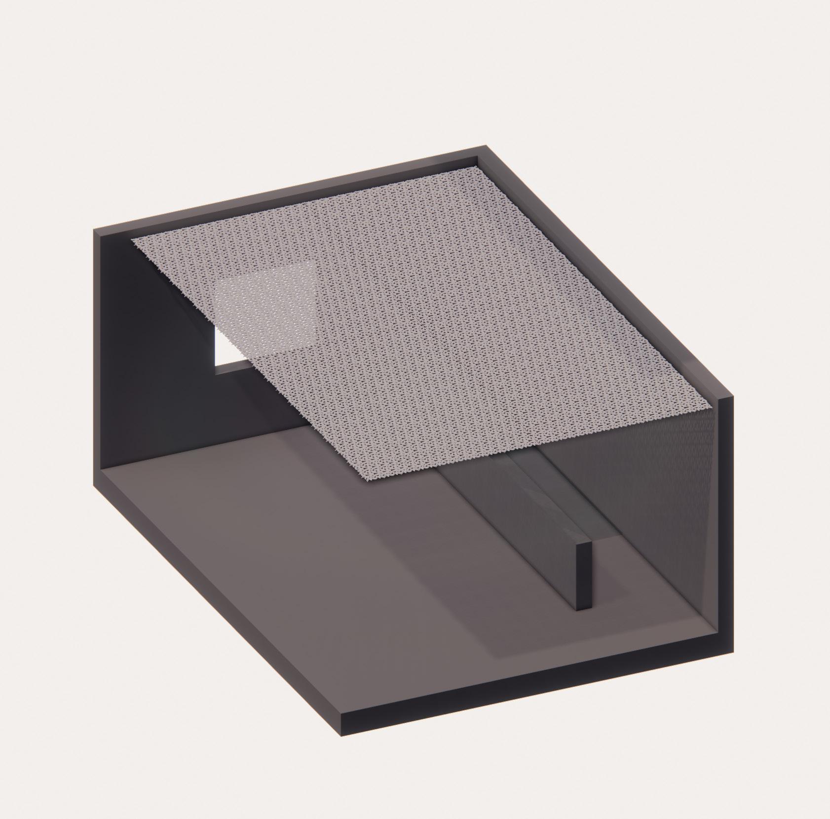
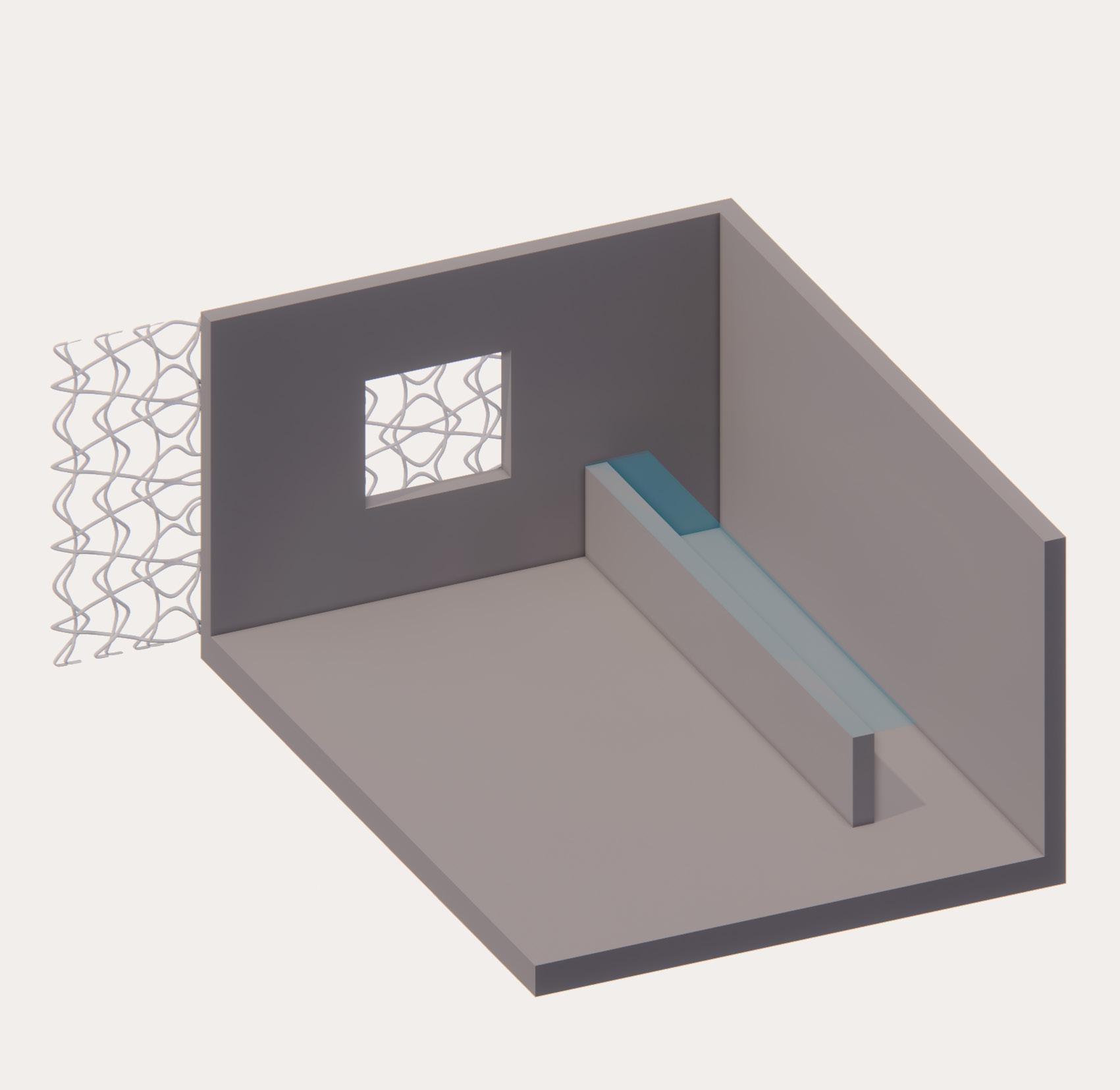
This is a modular design, therefore the design doesn’t stop at just this one wall. This system can be recreated on a multitude of scales and spaces.
To the right are my three proposals for other applications in a space. The classic vertical assembly can transition to desk space or vertical dividing walls. The second incorporated the idea of acoustic panels as moss has sound absorption abilities. The third is the idea of putting this application on the outside of buildings and starting to create a double skin facade. This would likely only be on the north side of buildings, or would need an incorporated shade structure.
VERTICAL ASSEMBLY
IMAGE: Alternate modular systems
ACOUSTIC PANEL ASSEMBLY
EXTERIOR BUILDING ENVELOPE ASSEMBLY
CONCLUSIONS
FUTURE RESEARCH
MATERIAL STUDIES
The material studies on this page were highly successful. The moss is adjusting to it’s new home. Moss has a slow growth timeline, so we wont see much change for another 6 months, but I’m looking forward to continue to watch these guys grow over the next term.
The rendering on the far right shows the proposed moss gradient on a full scale size in the space.
In conclusion, this has been a great studio. I’m excited about this possibility that moss has in our indoor spaces and I’m looking forward to continue to see where biophilic design can work in other forms of large and small scale architecture.
