SCAFFOLD STUDIO
THE BEAK HOUSE
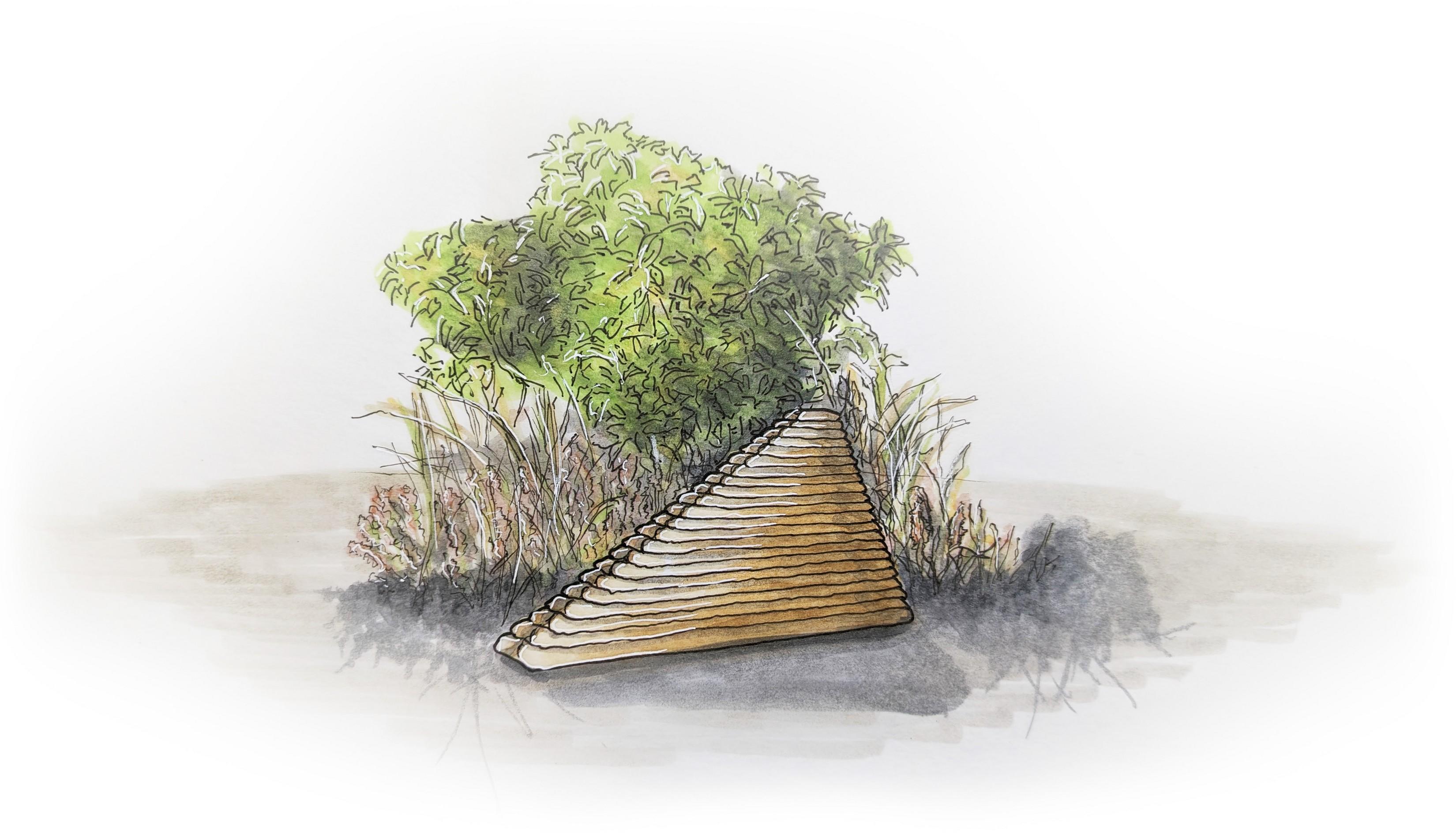

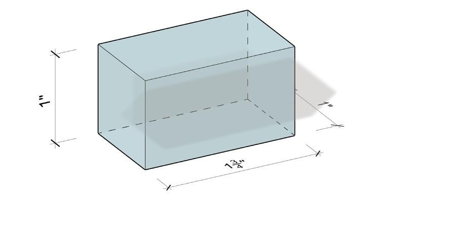

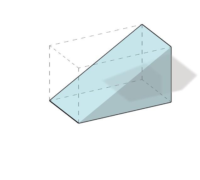
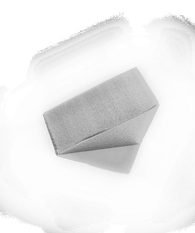
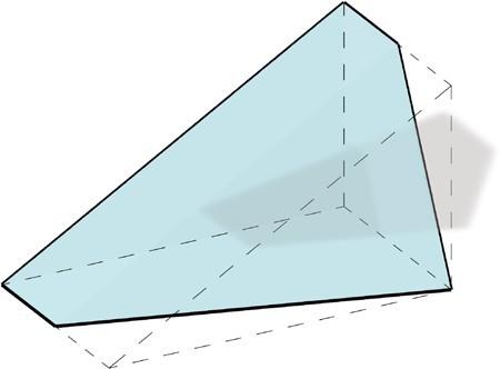
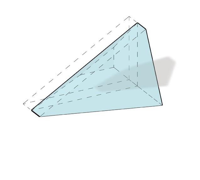
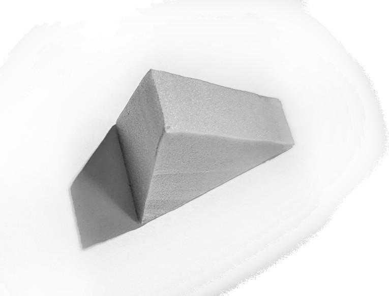
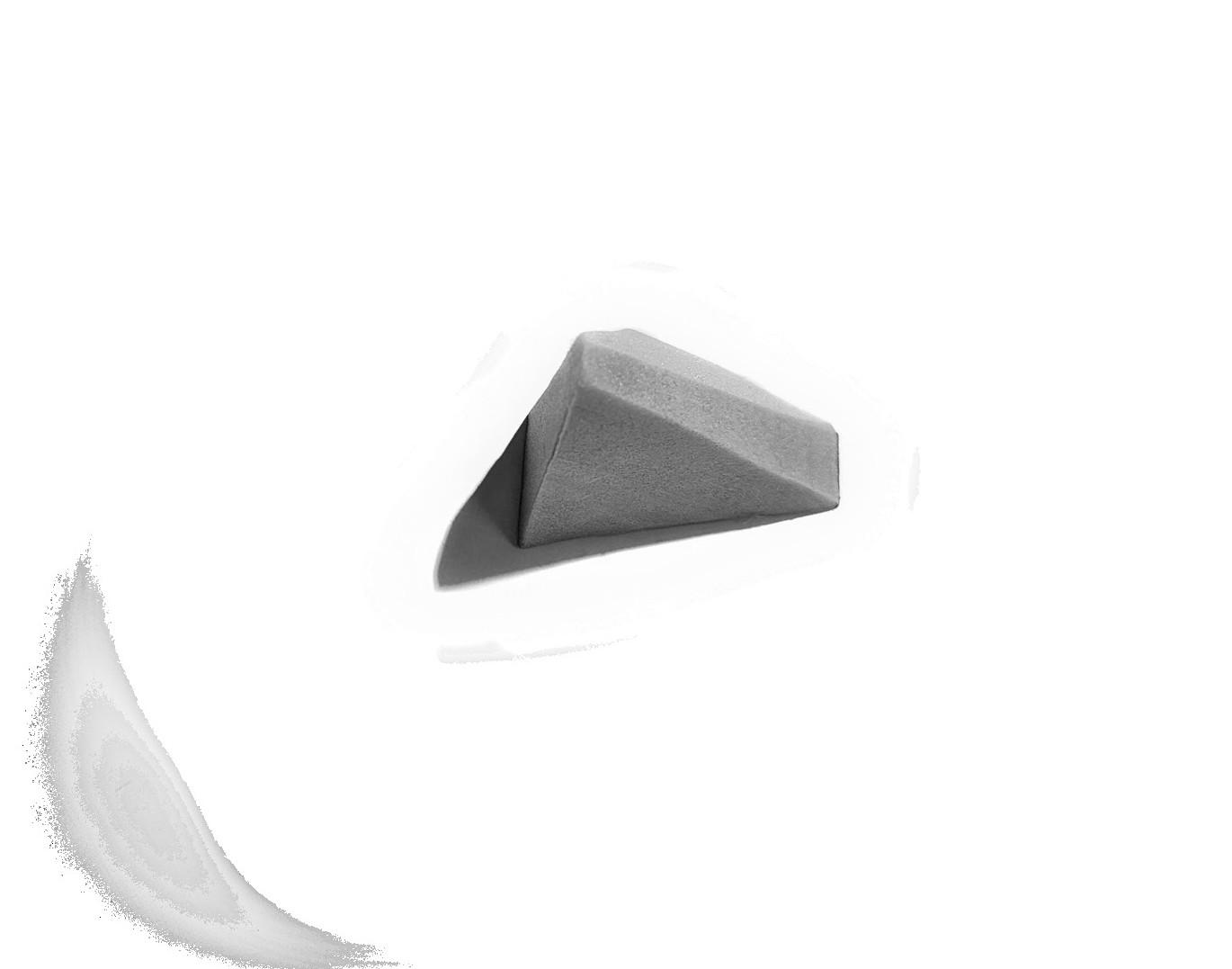
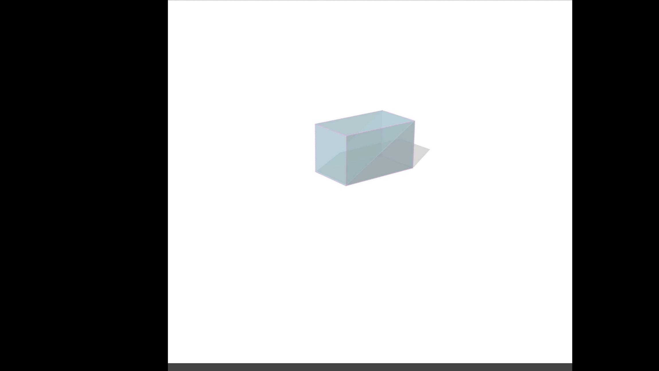
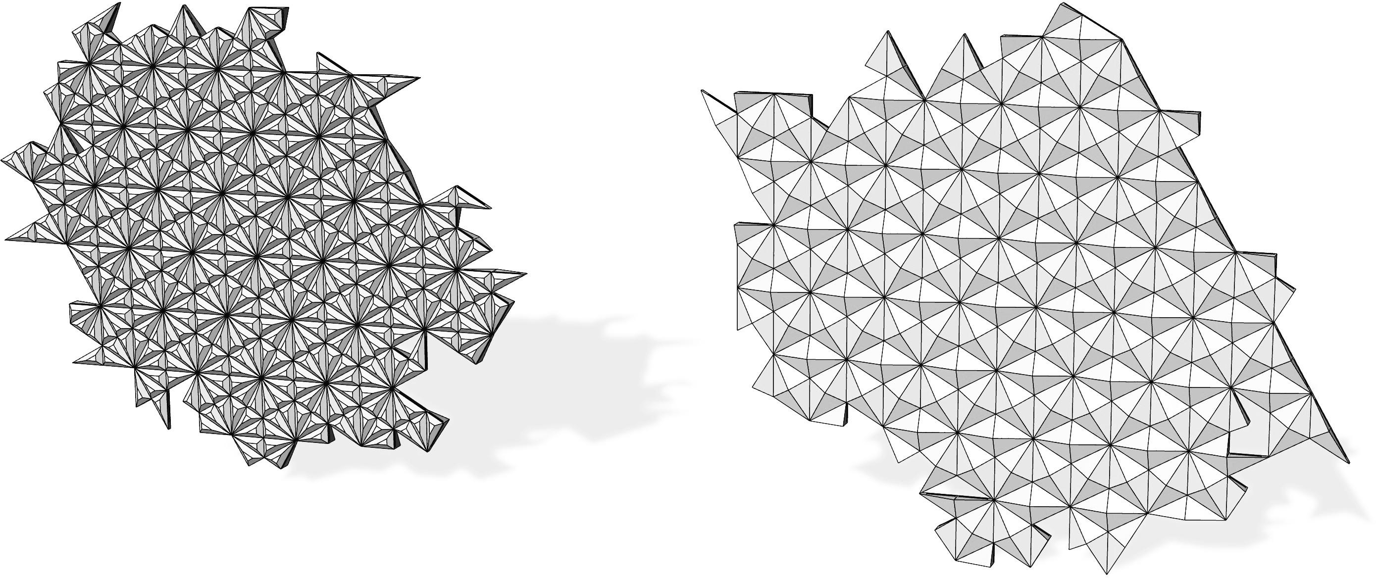
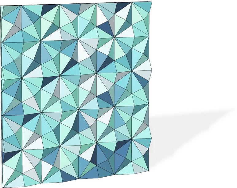
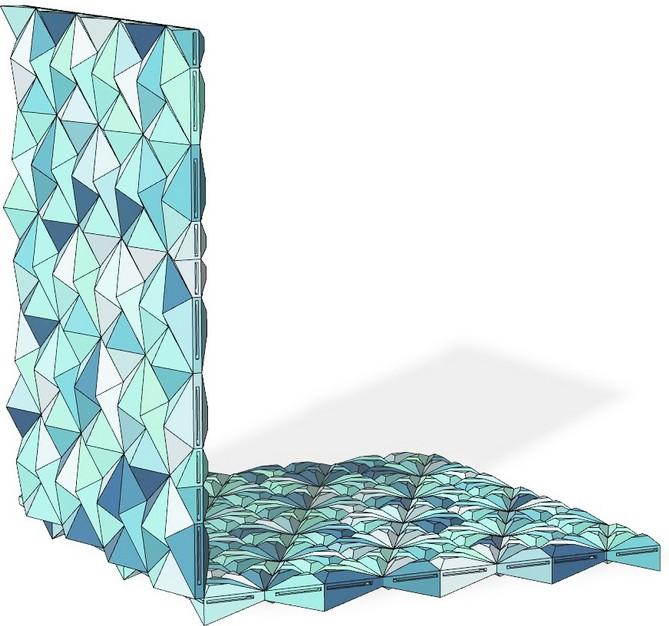
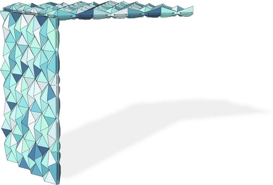
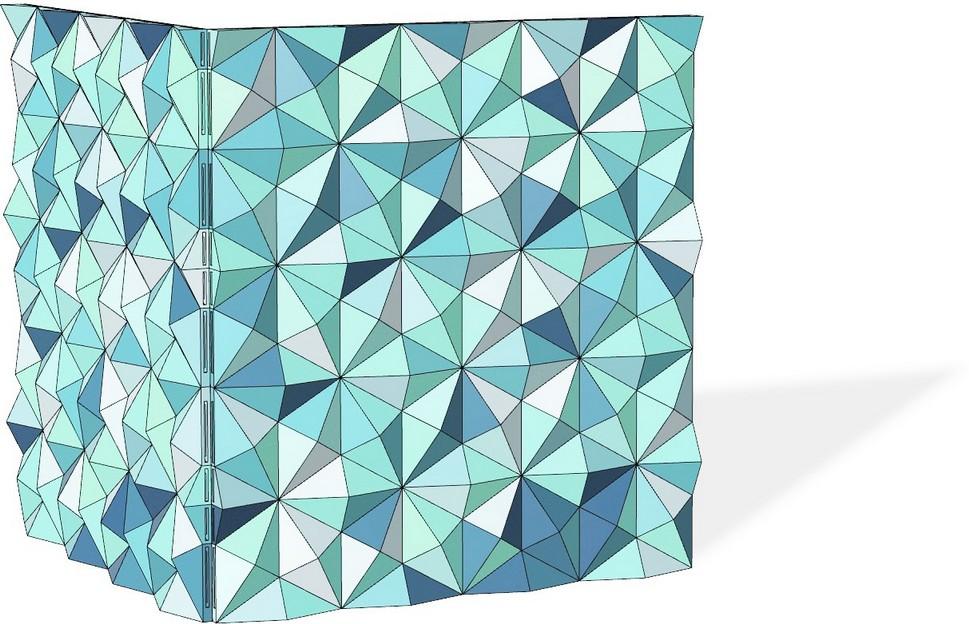
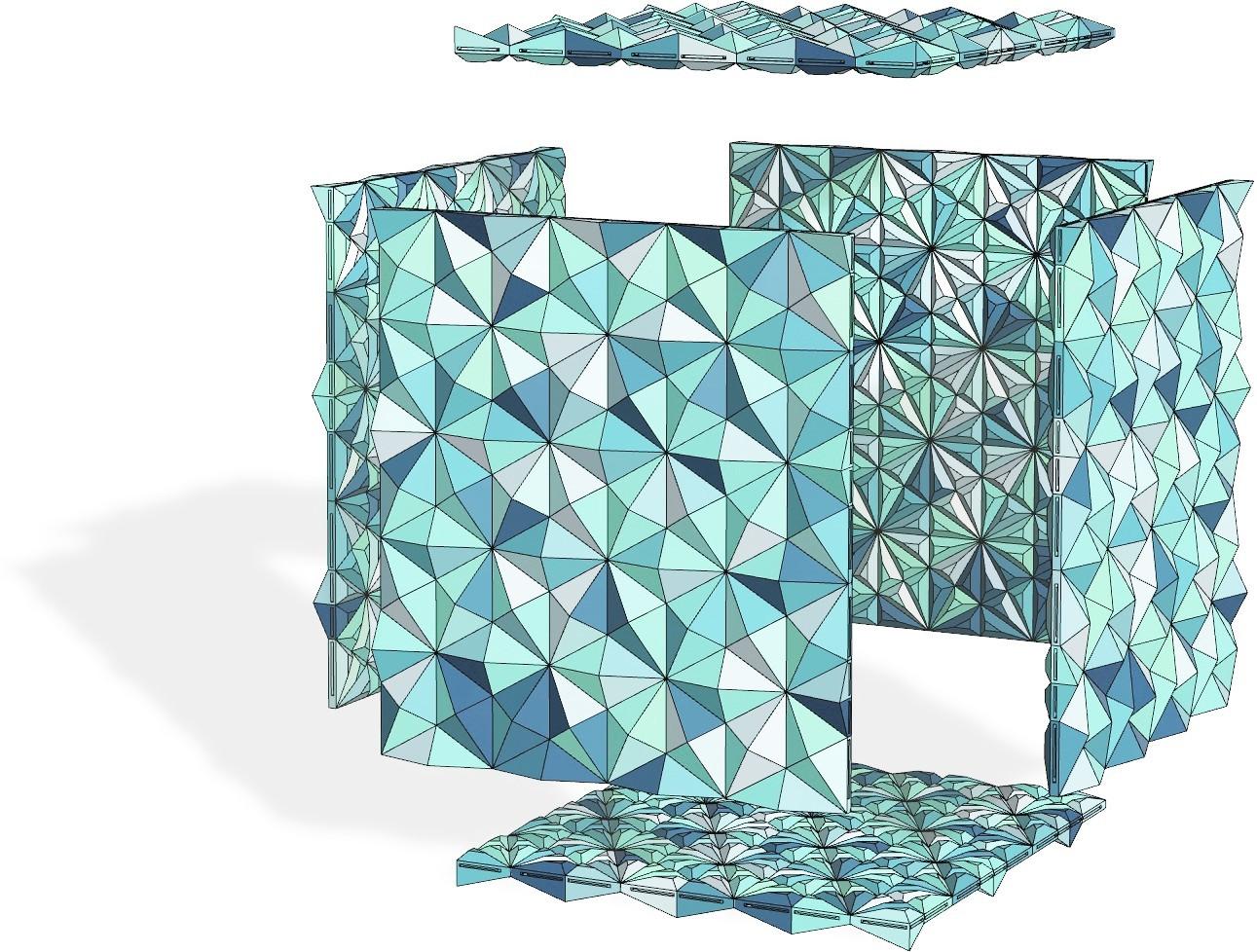
Figure 1 shows the initial exploration with no boundary conditions. The rule set is precise but simple, creating the desired hexagonal aggregation pattern. I then formed a planar wall by adding a rectangular mesh constraint to the aggregation. The rule set allowed for the component to fill gaps in the straight edge to form perfectly orthogonal
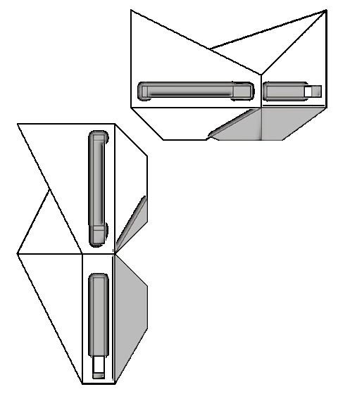
is chamfered at 45° to allow for more delicate corner connections while maximizing the abutting surface area. This works well for closed corners; open corners are problematic because the front and rear faces have differently angled planes that collide when set perpendicular. Floor and ceiling planes fit neatly into the chamfered edge when on module, but slip past and collide when not.
POROSITY COMPONENTS
PHYSICAL FABRICATION
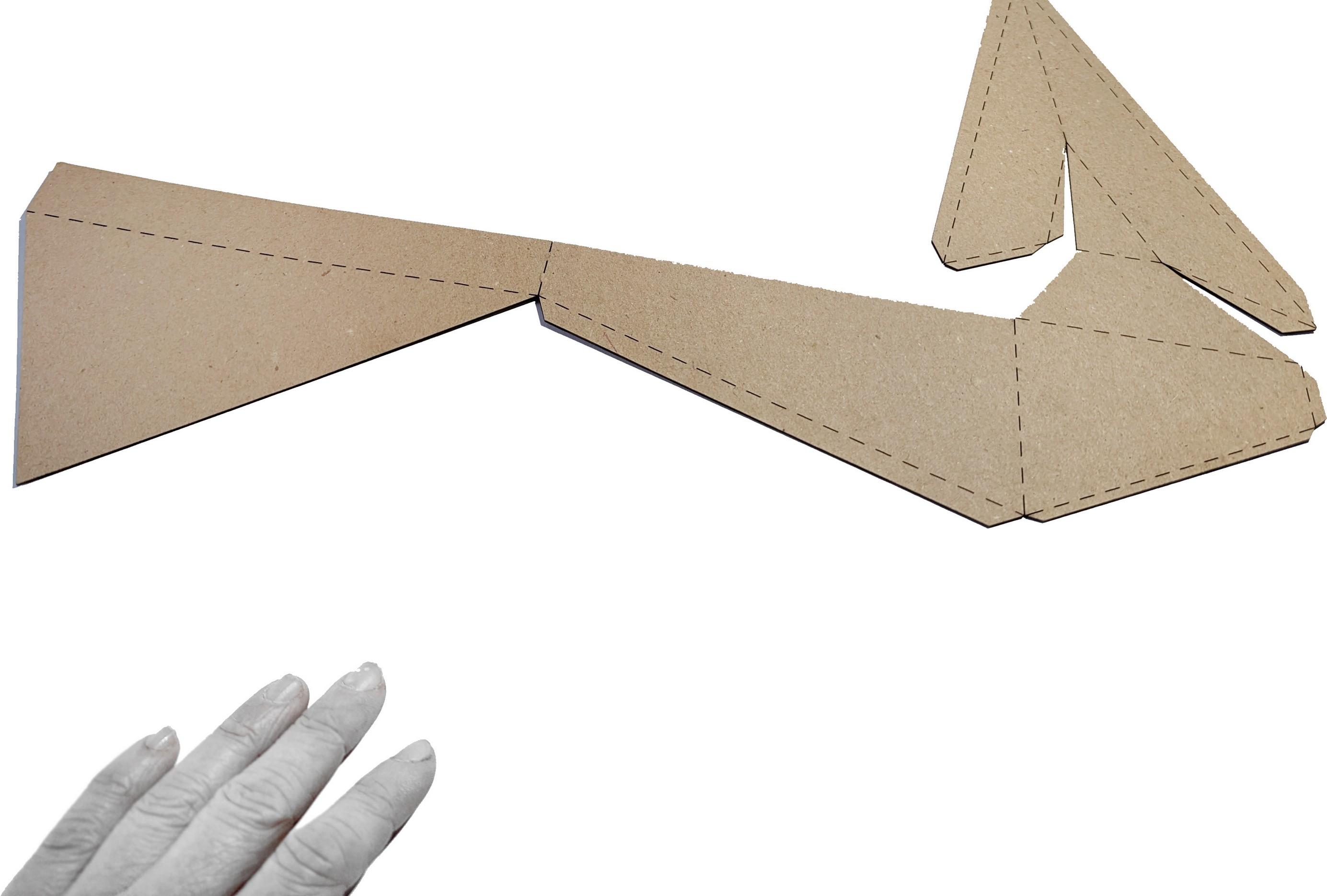
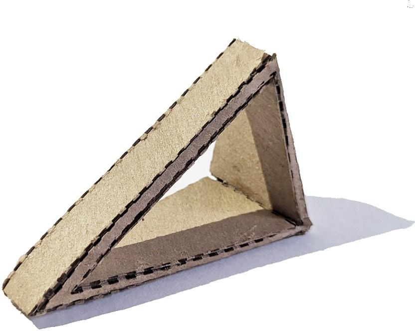
After creating each component in Rhino, I used the “Unroll” command to create foldable templates for each porosity component. I added tabs to each side of the beak for ease of gluing. Fold lines were scored on the laser cutter using a dashed line; I did need to score manually
to avoid crushing of the material at the crease. The first component, 0% porosity, folded and glued together easily. The second, 40% porosity, was also fairly straight-forward, although I removed the interior tunnel and instead left only the tabs to shield the inside from view.
third component, 80% porosity, was the most difficult due to the thinness of each edge. The chipboard I chose to use was slightly too thick for such tight creases, and tended to bend or crush under the effort of pushing on it so hard. The tabs were also more difficult due to small margins of error.
If I were to create 3D components out of paneled sheet goods, I would be more selective when choosing a material. The double scoring technique was effective and the dashed edges add a certain diagrammatic feel, although it would be more distinct on
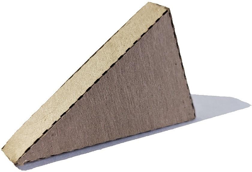
0% POROSITY
THE BASE BEAK
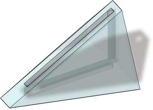
The base component was not altered to create a different porosity level but instead was used as is to act as the most private block type. This block is also useful in shielding the interior from hot solar gain, especially important given the humid subtropical climate in Dallas.
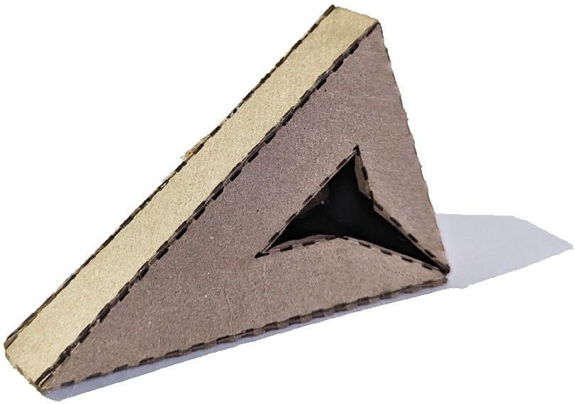
40% POROSITY
THE NESTING BEAK
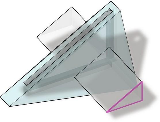
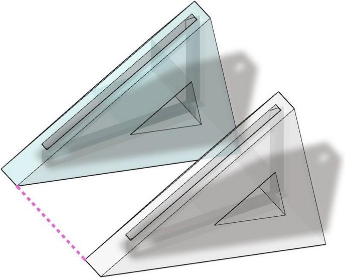
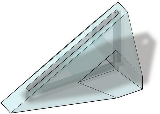
The base component was altered to 40% porosity by extruding and applying a Boolean difference to the rear face. I then nested one into the next by aligning the corner points and applied another Boolean difference. This allows them to fit together perfectly when aligned.
80% POROSITY
THE WIREFRAME BEAK
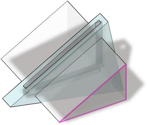
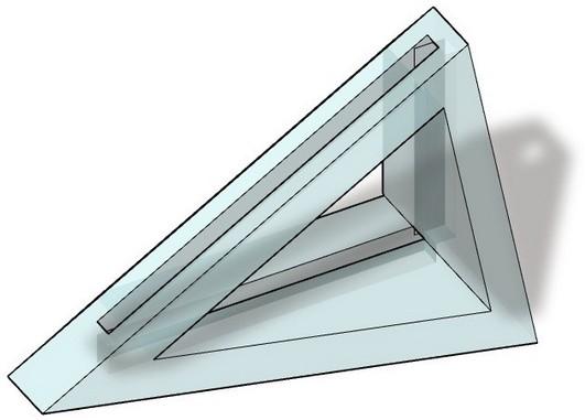
I created the most porous component by extruding the component’s silhouette when viewed head-on. I then offset it by 20% inward to create a smaller triangle. This was extruded through the original component and a Boolean difference command created a large hole in the
CHASE
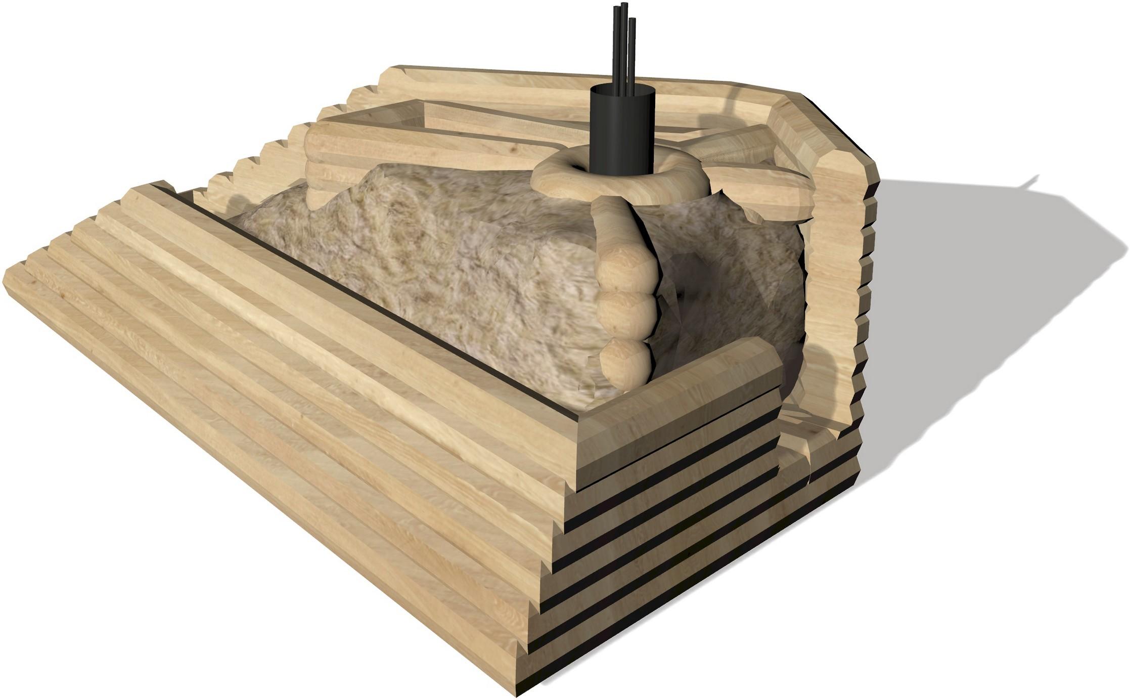
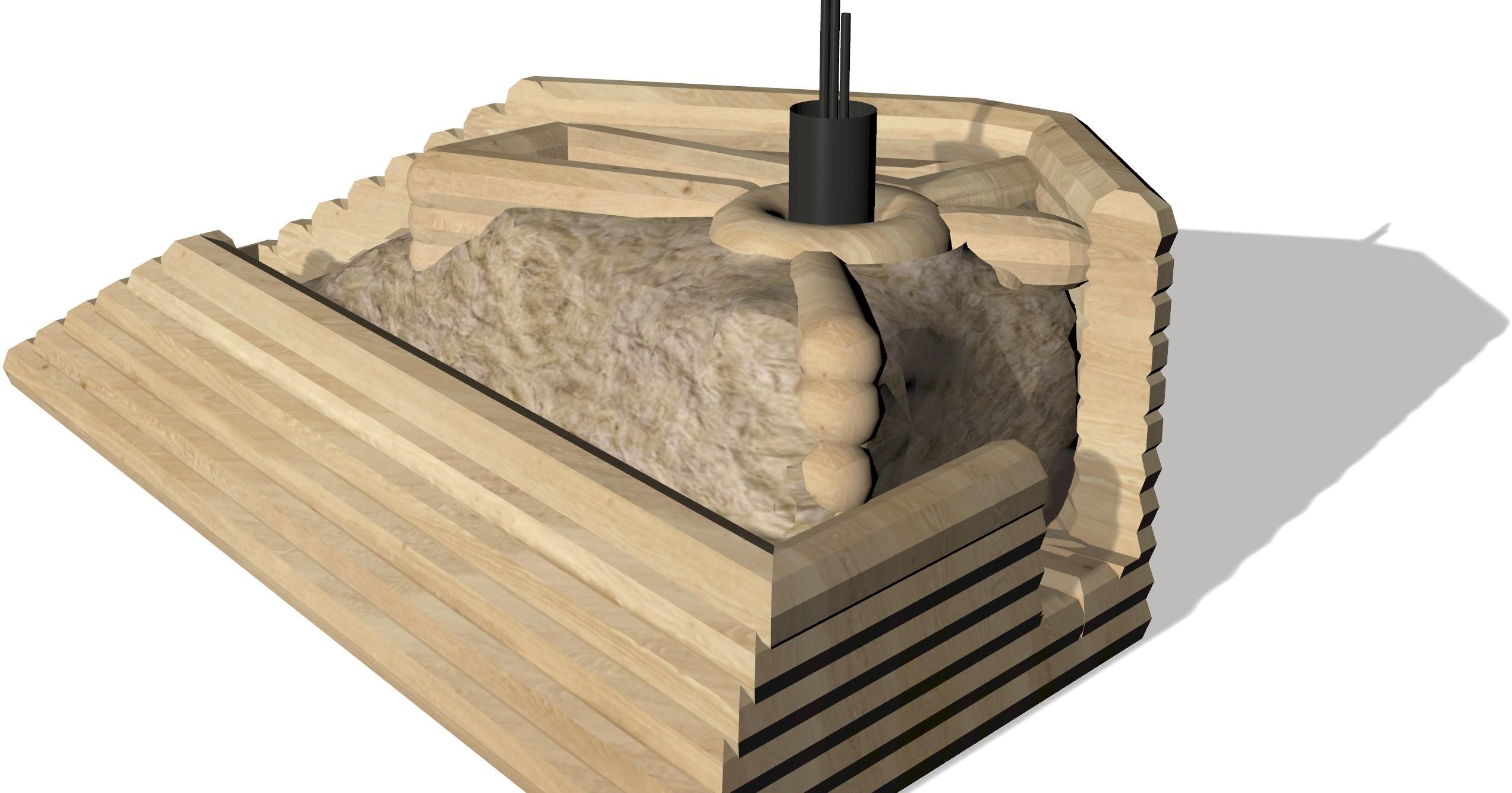
The Beak Block acts almost as a 3D-printed SIP in brick form, created and assembled off-site in controlled conditions. This version prints with a cornbased biopolymer mixed with wood waste. The enclosed, insulated block is then shipped to the building site in compact stacks, allowing for immediate use upon
WALL BEAD; 2” INFILL;
TRIANGULAR ROCKWOOL; BLOWN
CONNECTION SLOT
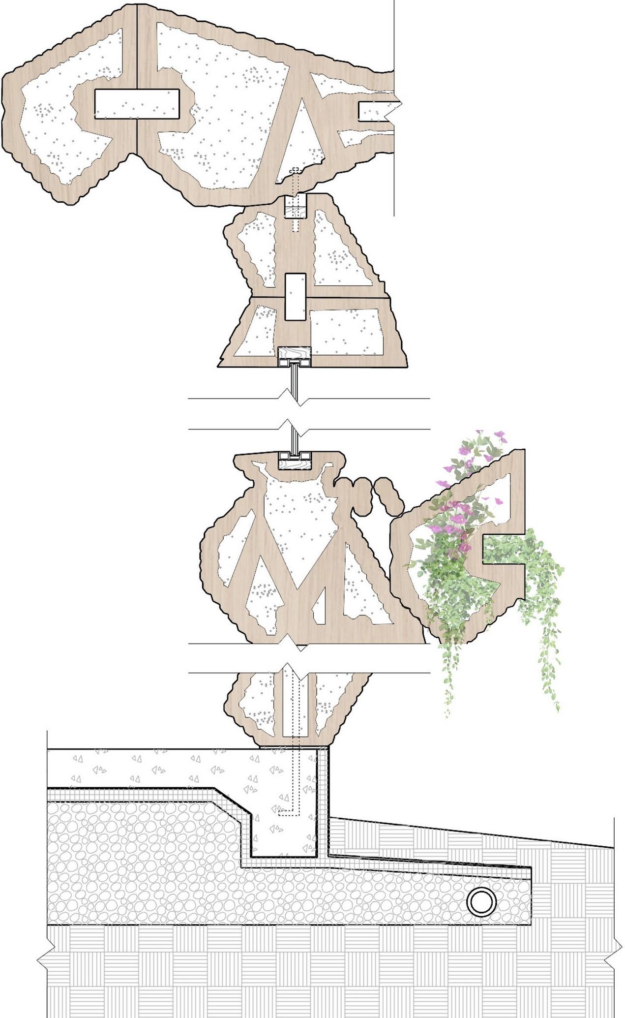
SAWDUST-BASED EXTRUSION BEAD; 2” DIAMETER
3D PRINTING INFILL; TRIANGULAR FORM
POST-TENSIONED STEEL BOLT; 1” DIAMETER; ROOF TO WALL
ROCKWOOL INSULATION; BLOWN LOOSE; R-50
CONNECTION SLOT; RIGID INSULATION GLUED
WINDOW FRAME; INSET INTO SLOT; COMPOSITE
WINDOW; DOUBLEPANED GLASS; GASFILLED
WINDOW OPENING BLOCKING; DOUGLAS FIR 2X6
EXTERIOR TRELLIS BLOCK FOR NATIVE PLANT GROWTH
POST-TENSIONED BOLT; THREADED TO TOP OF BLOCK
BASE PLATE; POWDERCOATED STEEL; BLACK CONCRETE SLAB WITH THICKENED EDGE; 20% FLY ASH
VAPOR BARRIER
PROTECTING SLAB; 12 MIL THICK INSULATION FOR SLAB; RIGID POLYSTYRENE; 4” THICK
ALUMINUM INSULATION COVER; BLACK POWDER COAT
GRAVEL FOR DRAINAGE WITH EMBEDDED DRAINAGE PIPE
DRAINAGE MAT AND SOIL BELOW
DISCRETE FABRICATION
BLOCK PRINTING
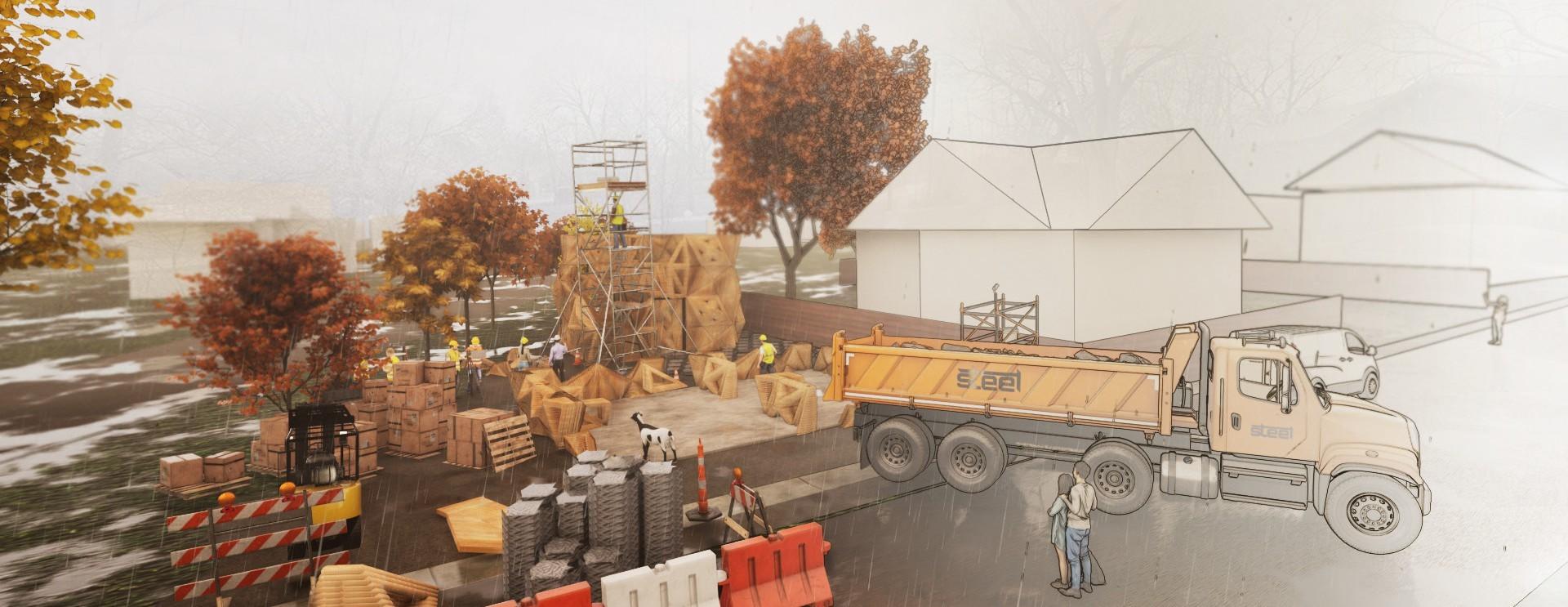
Discrete fabrication has many advantages to on-site continuous printing, including controlled climate conditions and no site limitations.
Cementitious 3D prints currently struggle to run in low winter temperatures, thus limiting the construction period to fewer months of the year in many geographic areas.
The site must also be easily accessible and reasonably flat, as the printer rails require a flat bed and truck access in and out of the site.
Printing blocks in a predetermined factory environment negates these challenges, offering the ability to print constantly regardless of outdoor conditions.
Blocks are loaded onto trucks for transport to the site, but the site itself is not required to be flat. This minimizes the construction footprint on the land and its surrounding ecosystems.
If the site is unaccessible by semi- truck, construction can still procede as each block is
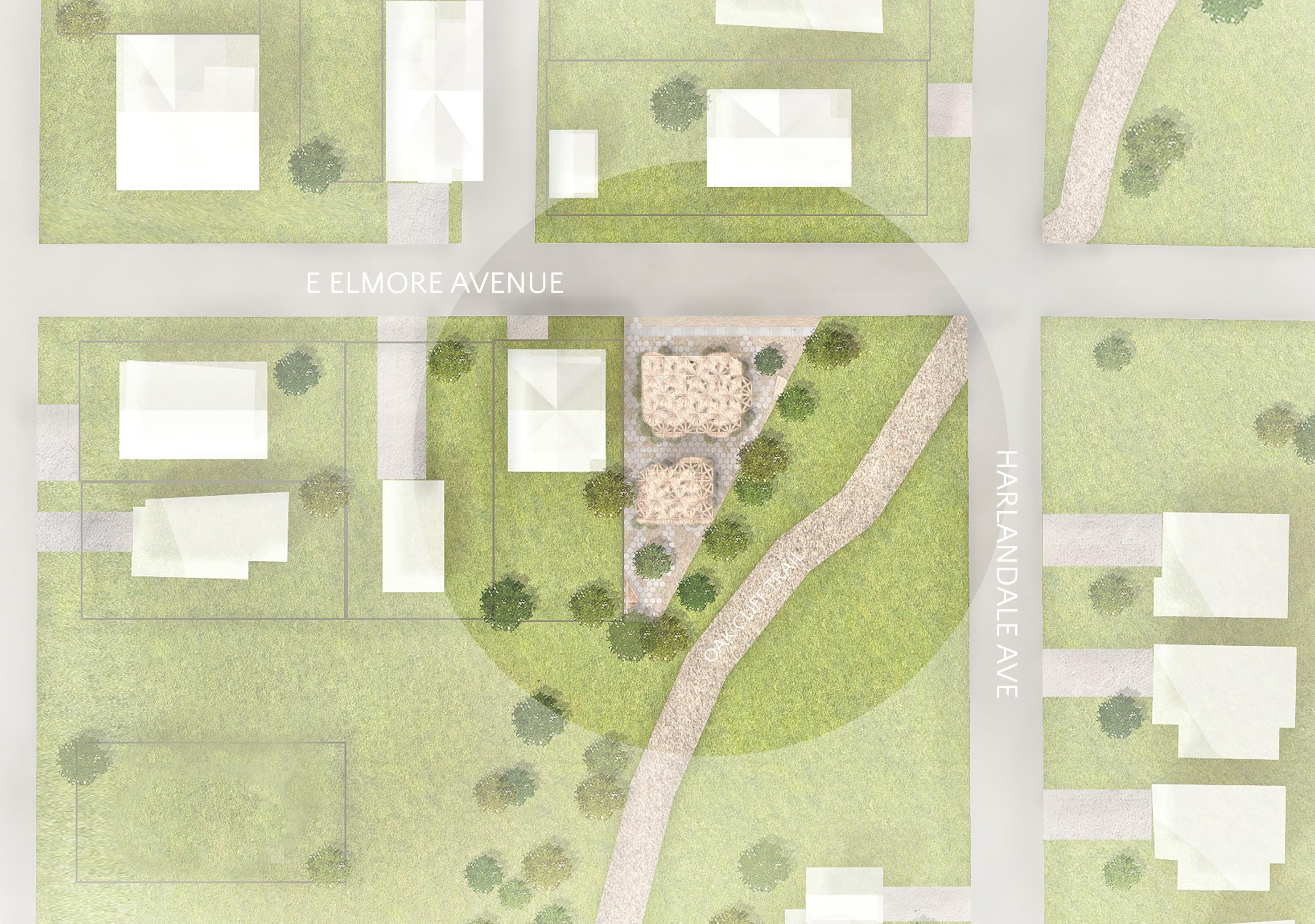
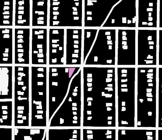
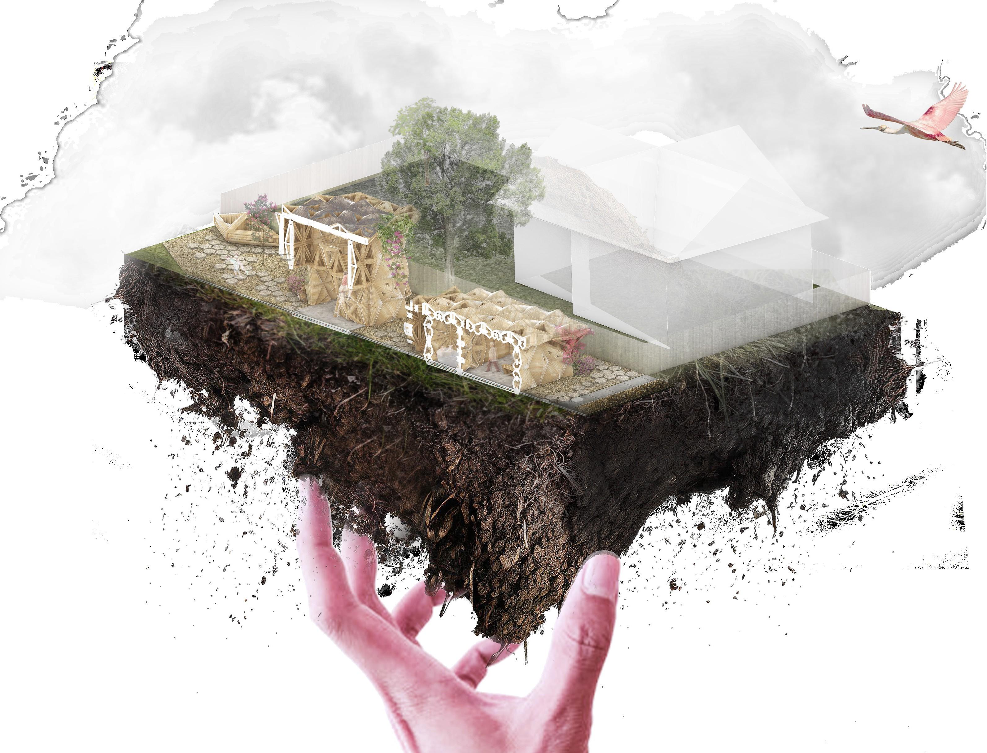
1016 East Elmore Avenue is in the southwest corner of Dallas, TX, only a five minute walk from the nearest DART station and convenience store. It is zoned R7.5A, the standard low- density residential zone for the city. There is a house directly across the street and one to the west; the north, east, and south boundaries are all uninhabited. The main access road
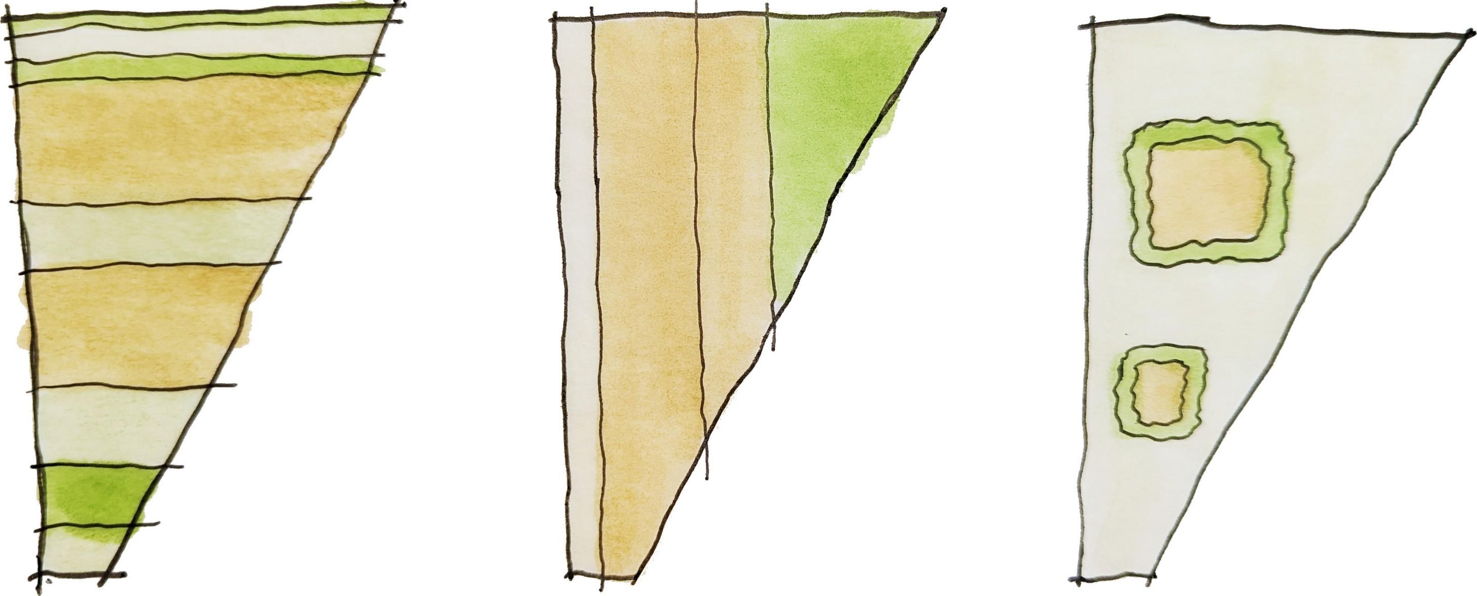
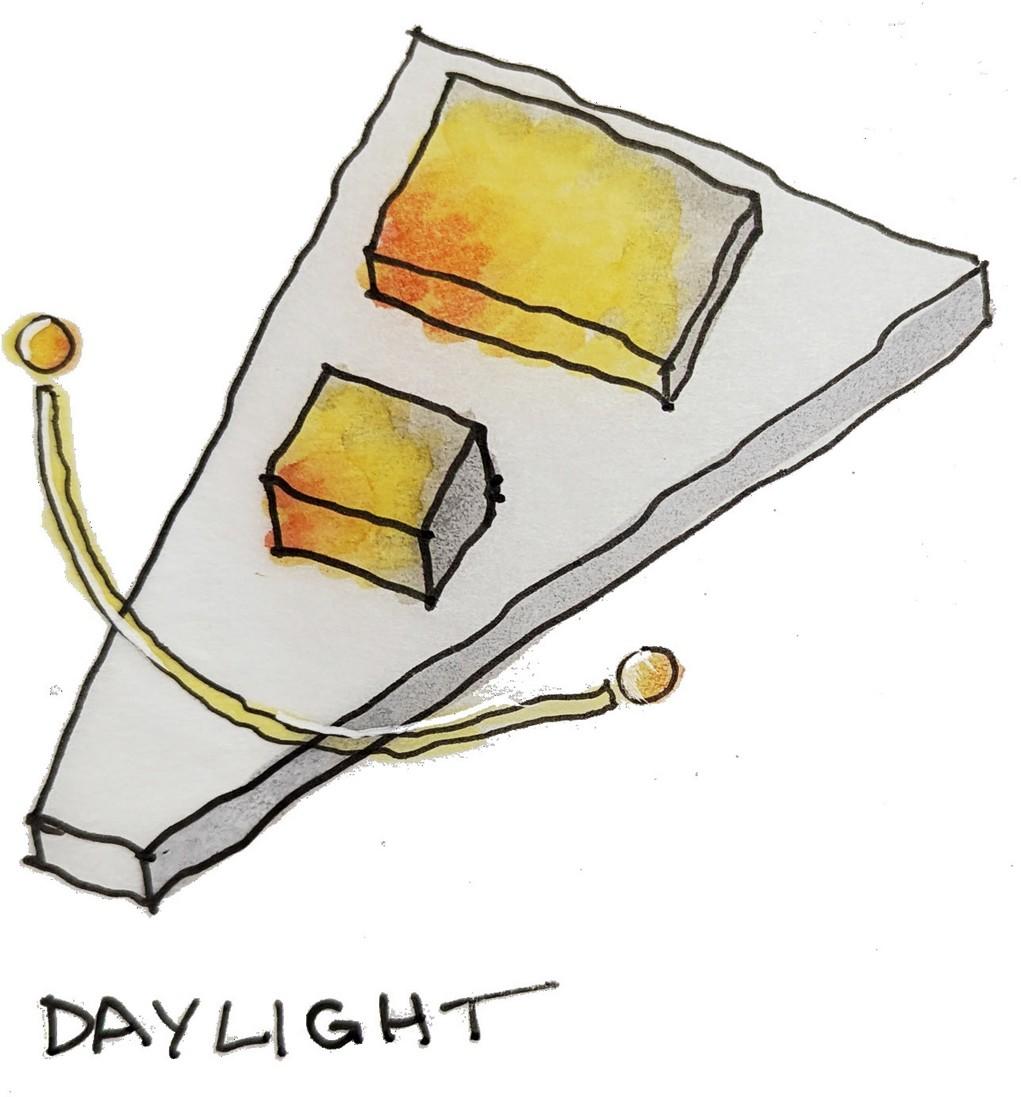
A walking trail runs along the eastern edge of the property line, creating a vegetated buffer between the lot and the adjacent cross street. The south end of the lot, although narrow, does have a view of the walking trail and green space behind the lot. I chose to divide the site into E-W bands of materiality and program, alternating between grass, plantings, paving, and
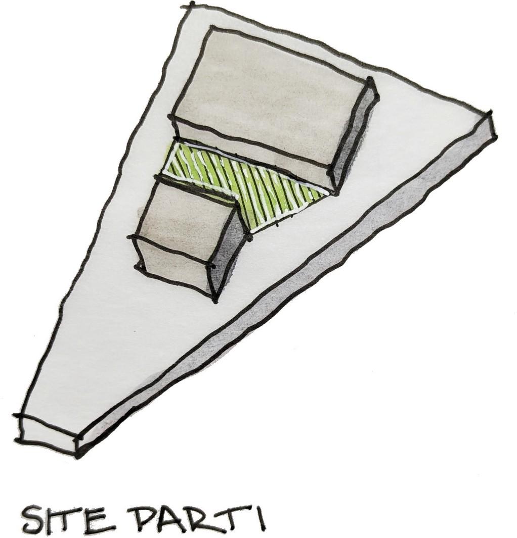
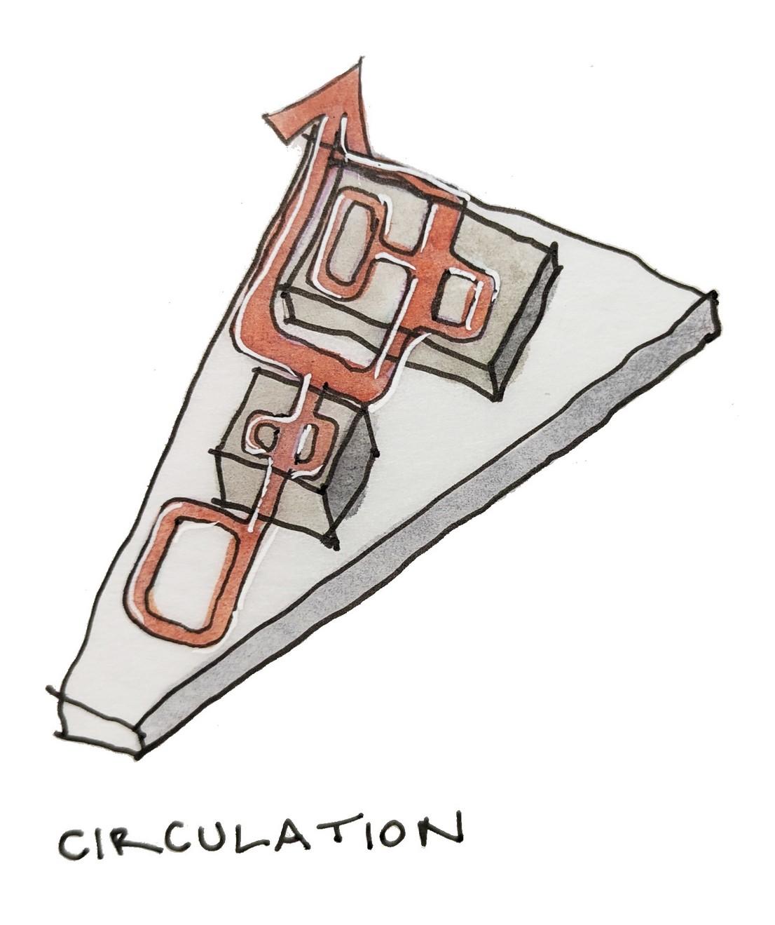
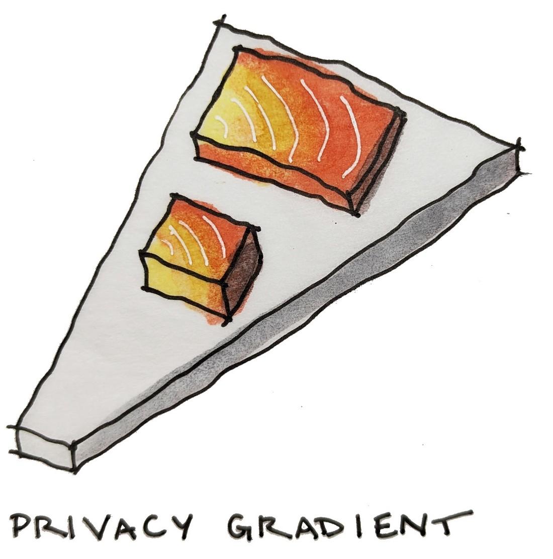
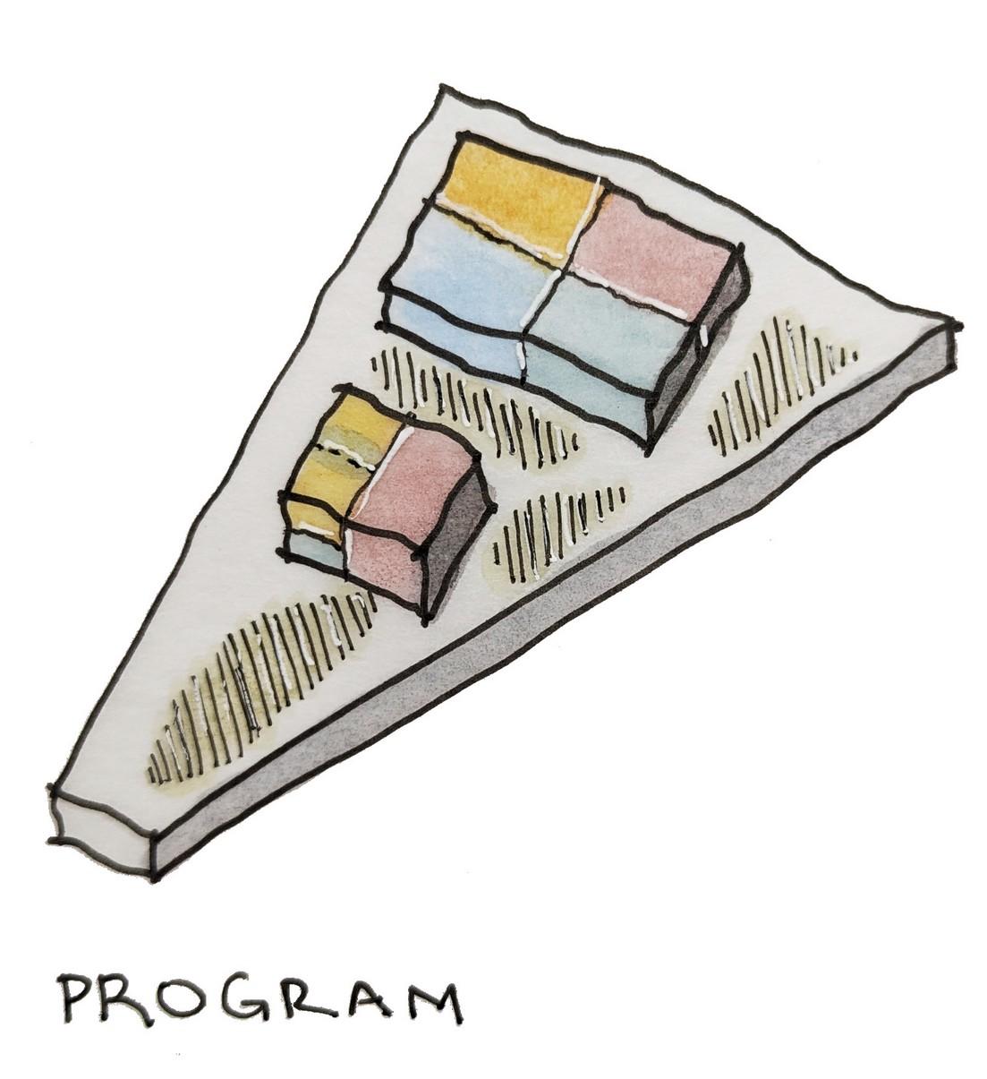
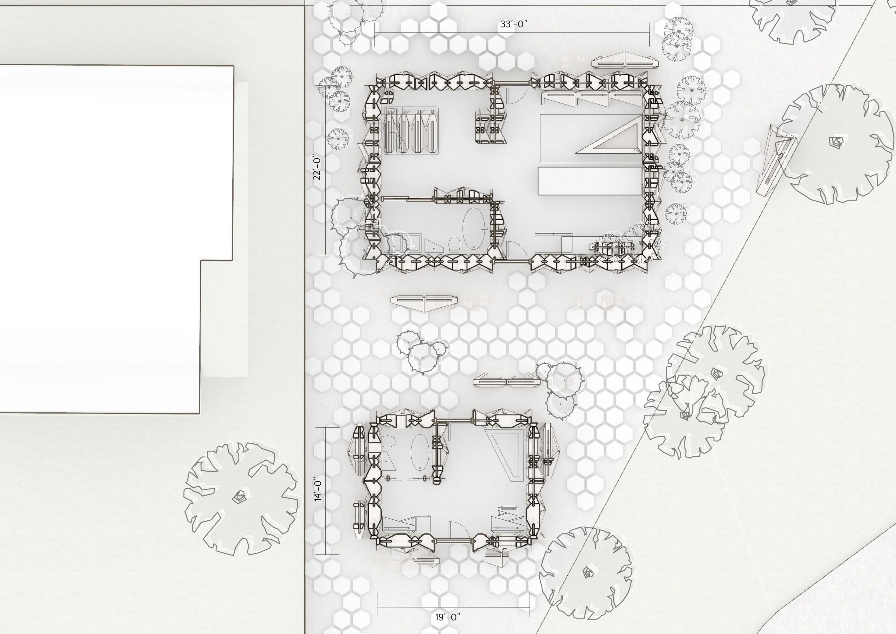
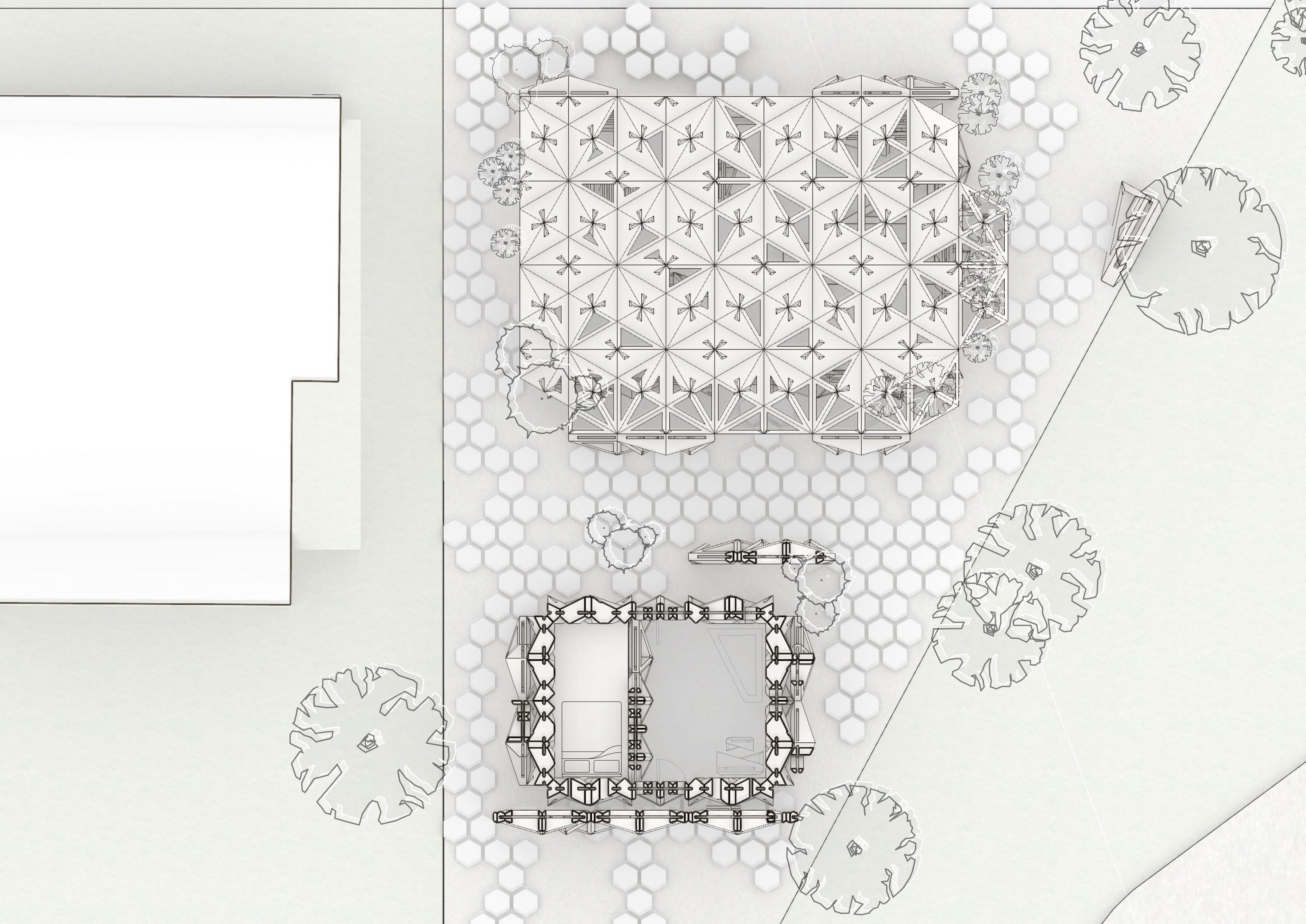
setbacks, I was only able to fit a one bedroom single-family residence and a small ADU in the backyard. The two structures are aligned along the west setback, providing a circulation path along the west side. The program is similarly organized along the N-S axis, with private spaces along the west, storage and service as a central buffer, and public space along the east
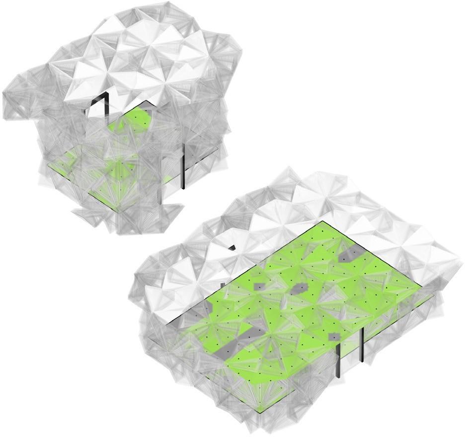
DAYLIGHT
AVAILABILITY
PERCENTAGE
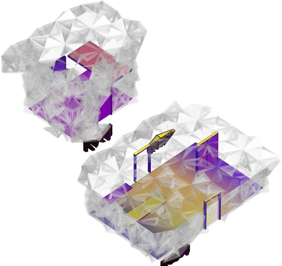
The daylight availability according to Climate Studio was excellent, with 100% of the spaces daylit when possible. This is easy to achieve due to the space’s small size and regular shape. Notably, the analysis did warn against excessive glare during afternoon hours because I did not add any blinds to the simulation. Due to the amount of windows, I will need to consider more shading than previously expected.
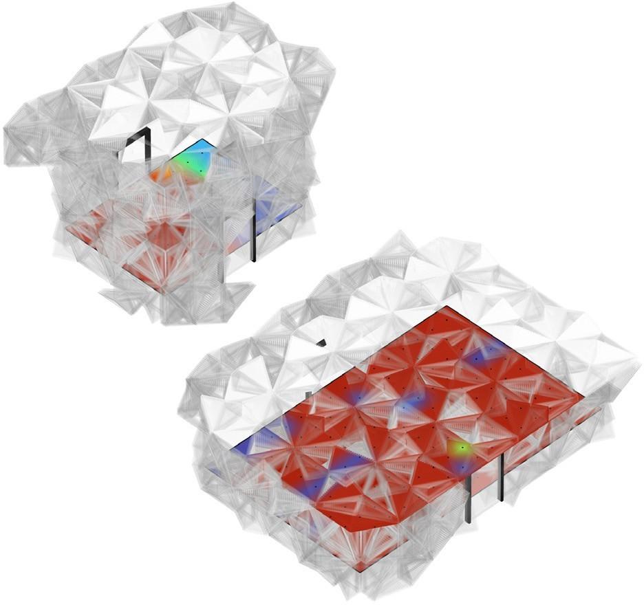
AVERAGE ILLUMINANCE
LUX PER DAY
The average illuminance in both spaces on a daily basis is much too high without blinds, curtains, or other shading devices. It’s reading at around 2000 lux, when it should be comfortably within the range of 100-400 depending on the space or tasks required. The only space that met this threshold was the kitchen in the ADU, since it was underneath the loft floor and was shaded from the skylights.
RADIATION MAP
kBTU/ft²
The radiation map shows optimal placements for solar arrays and the most effective locations for shading devices on the structure. The analysis shows that much of the building is shaded around the edges (most likely due to roof overhangs). The central spine of the single-story unit may need reduced overhead glazing or increased shading. Both roofs are well-situated to house expansive PV arrays to block and capture southern sunlight.


PHOTOVOLTAIC ROOF
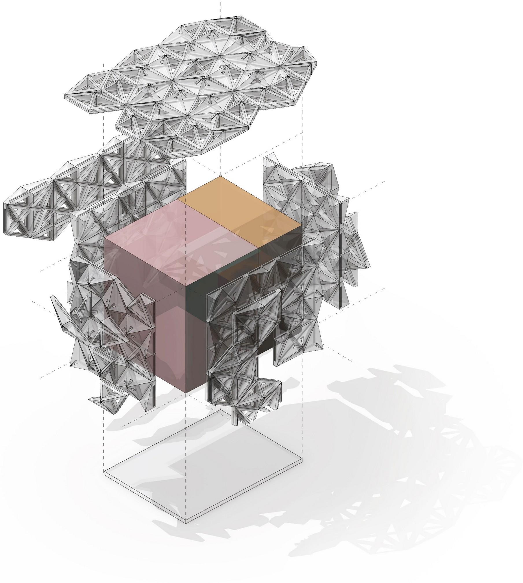
Non-porous roof blocks can have 3Dprinted PV cells embedded into a supersurface layer during fabrication to offset energy usage

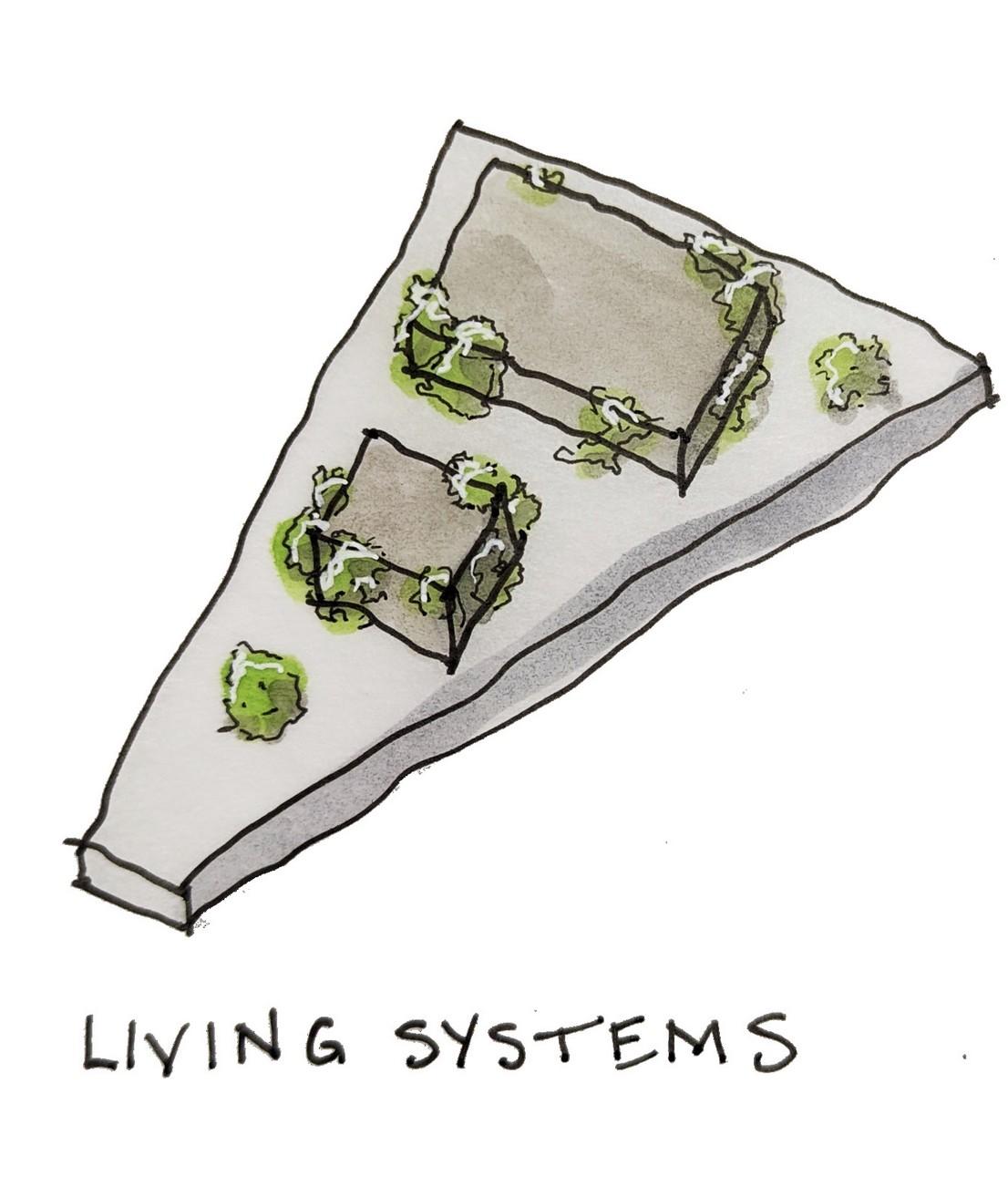
DEEP OVERHANGS WITH LIVING SYSTEMS

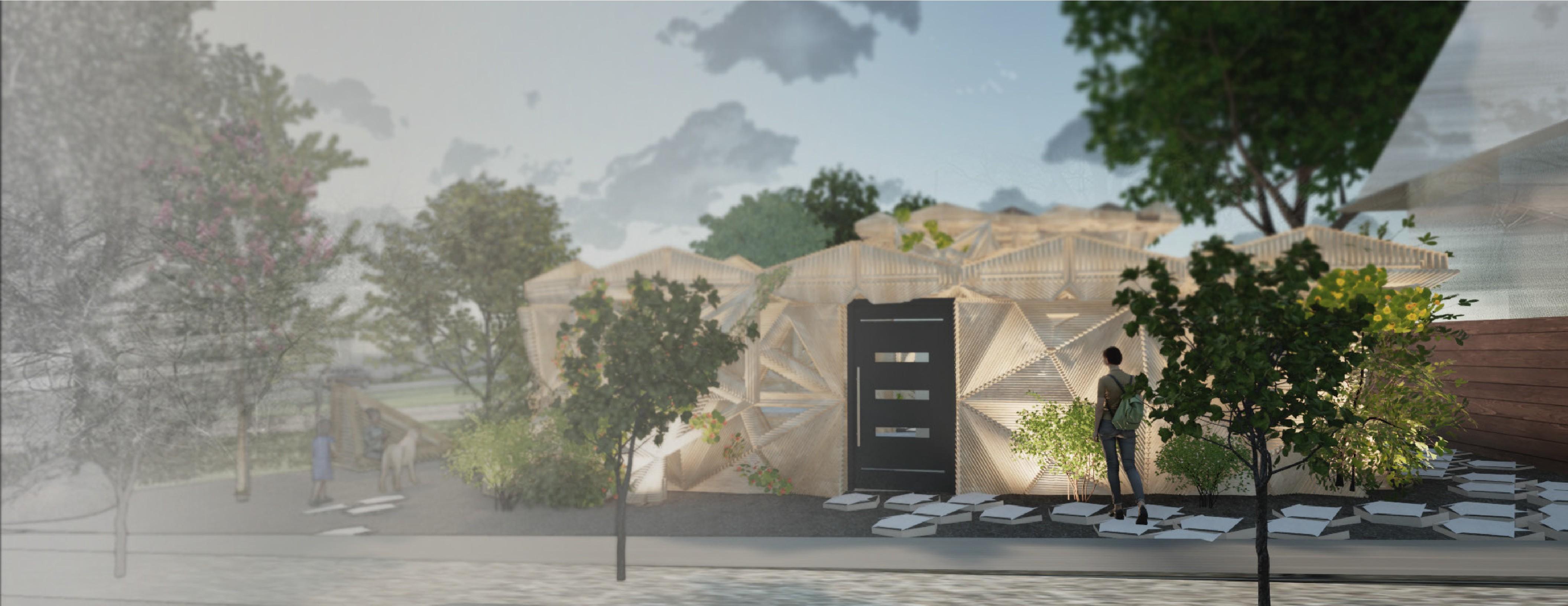
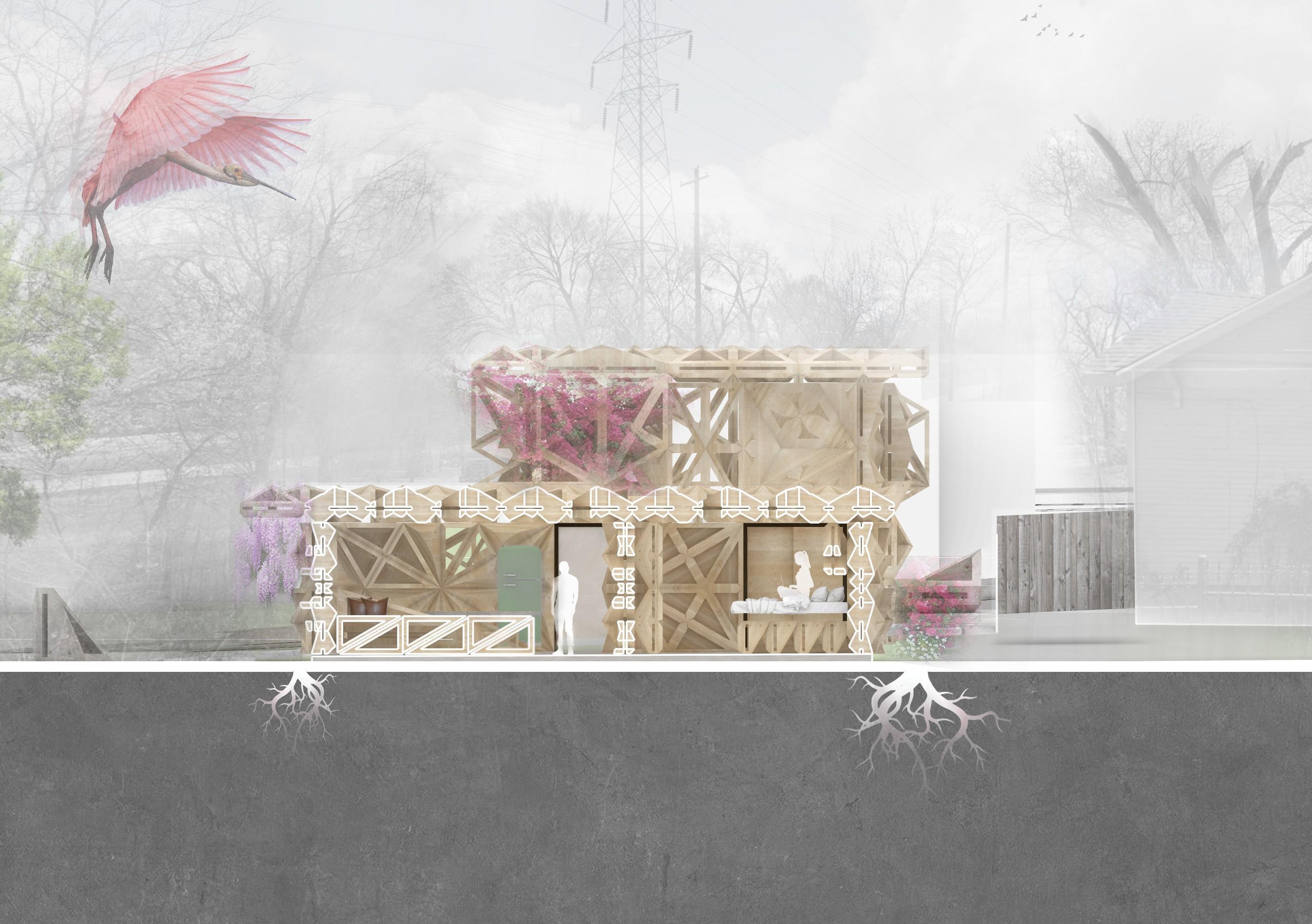
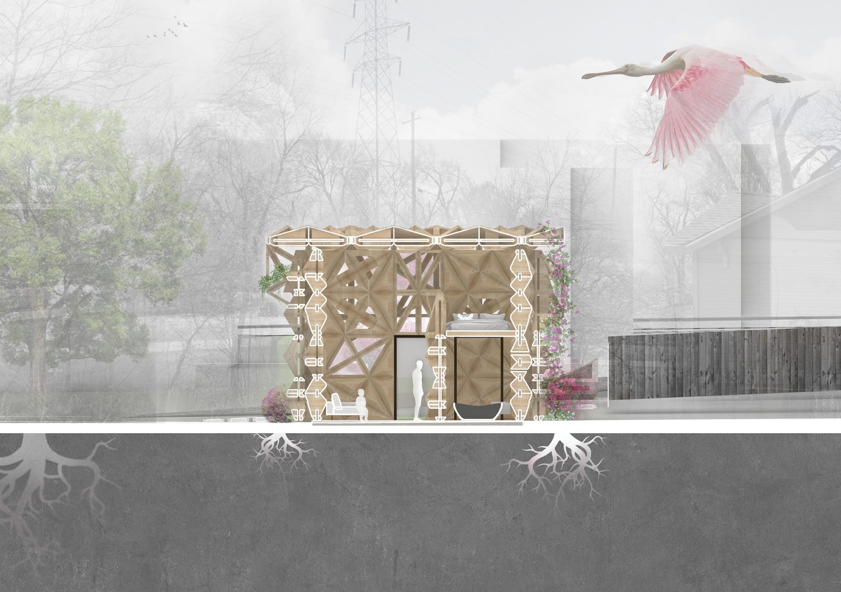
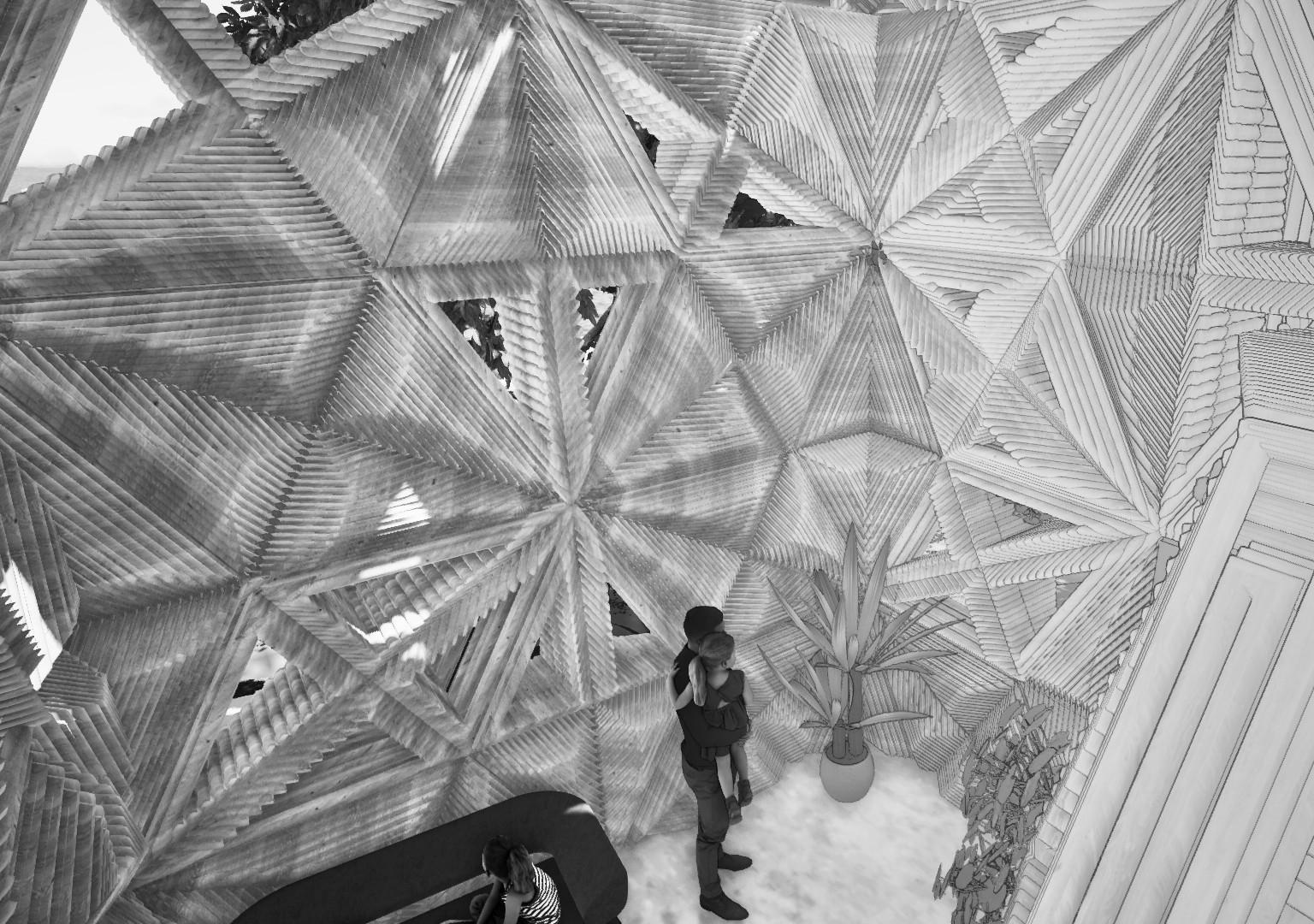
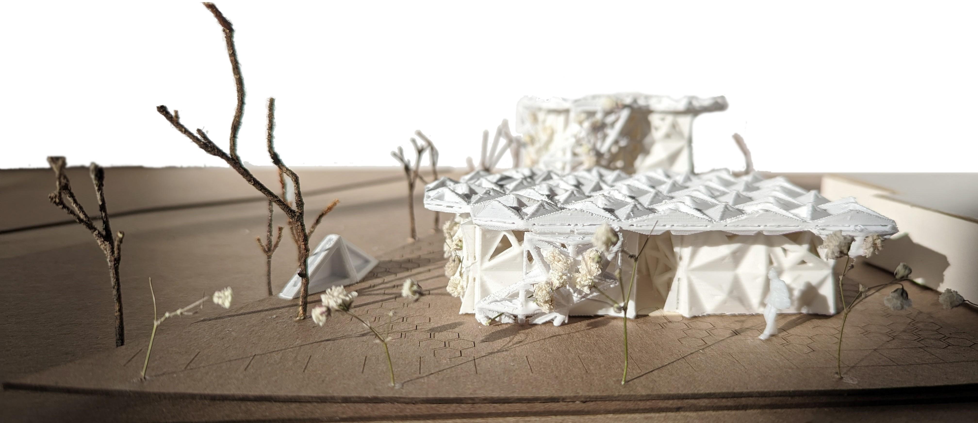
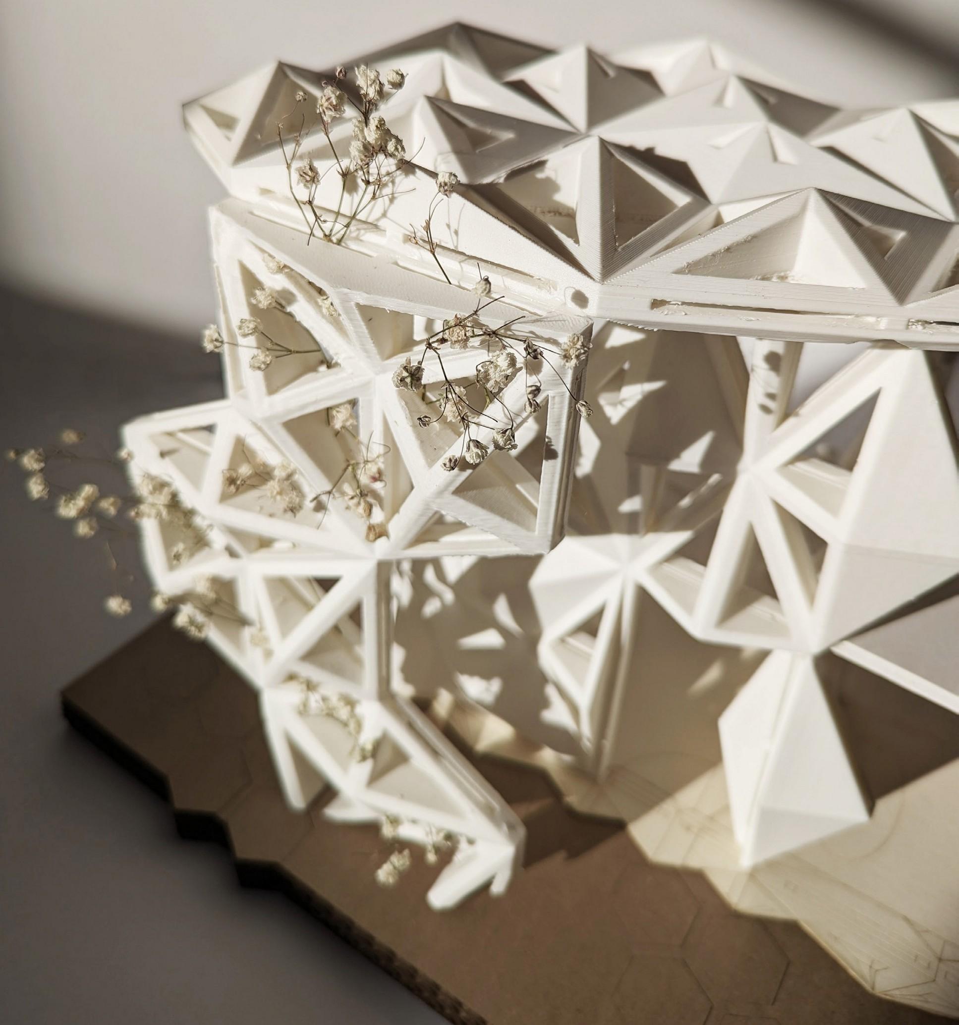
Roof overhangs vary in porosity and can act as support trellises for climbing plants native to North Texas, such as Crossvine, Coral Honeysuckle, and Passionvine. Vertical plant growth reduces solar gain and glare inside.


ENVIRONMENTALLY-CODED POROSITY

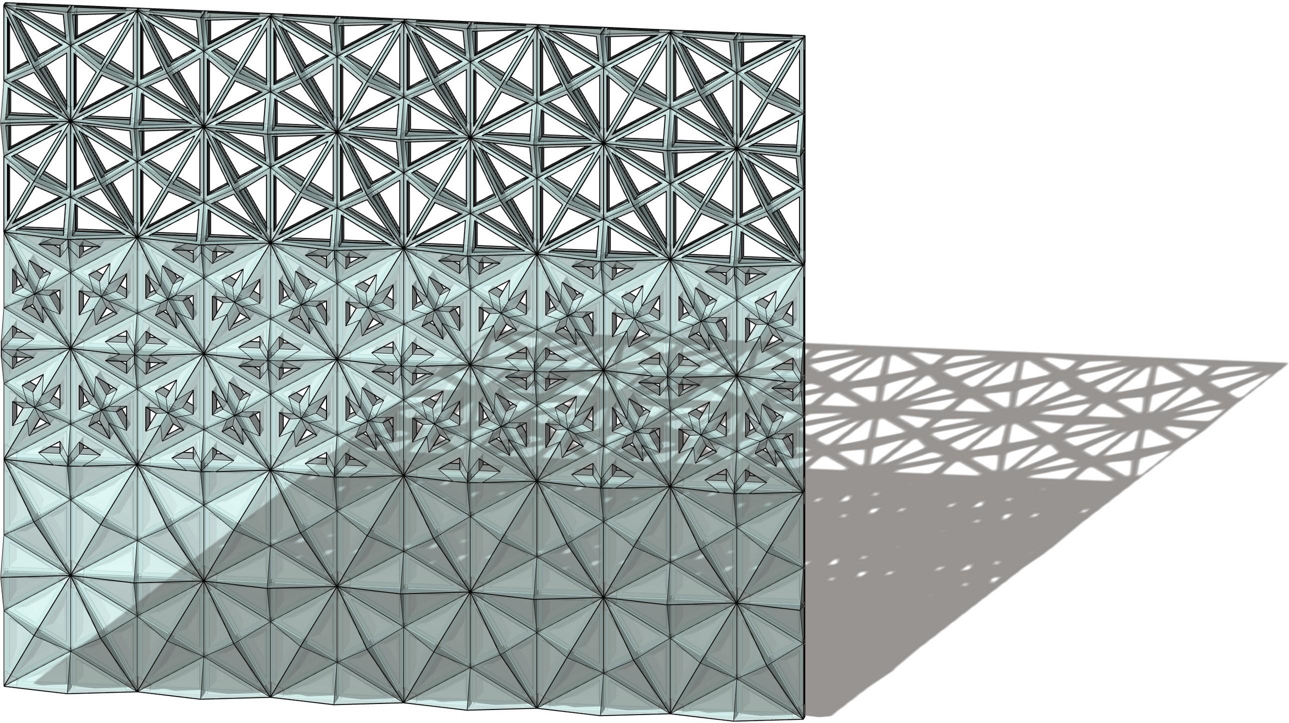
North and east facades maximize porosity to utilize diffuse, cool light while south and west facades limit large openings to keep interior spaces cool from hot afternoon sunlight.
CROSS-VENTILATION

Doors align in both units to allow N-S cross- ventilation throughout the space. Wind is funneled E-W between buildings and guided by the wavy surfaces of aggregated blocks.

RADIANT FLOORING
The polished concrete floor doubles as both foundation and conduit for liquid radiant heating and cooling. This is up to 40% more efficient than standard cooling mechanisms in hot climates. PERMEABLE PAVERS AND XERISCAPING
The site is covered in permeable paving, gravel, and native, drought-resistant plants to eliminate the need for irrigation and provide efficient drainage for stormwater runoff.

INTERIOR COURTYARD
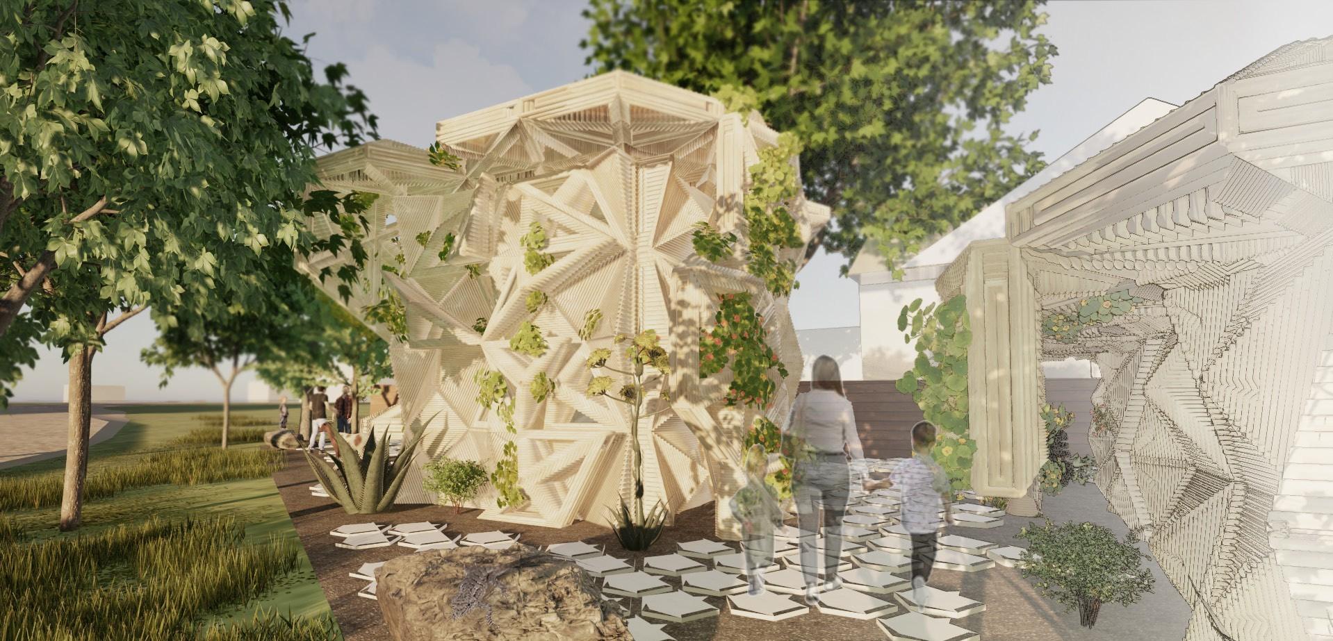
TRELLIS TUNNEL
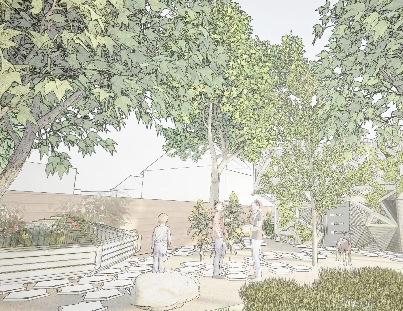
The space between the two units becomes a lush walkway lined with builtin trellis structures for native climbing plants to utilize. Surrounding trees enhance the private nature of the space and allow for much-needed shade in hot summer months.
