POMPIDOU II


I am a fourth year Architecture student with minors in Interior Architecture and Enviornmental Studies.
STUDIO GOALS
I chose this studio because it was a culmination of all my studies thus far. As an architecture student it is all very theoretical and this studio allowed me to understand the realities of designing and building something.

SECTION 1: SCAFFOLDS
MEW SCAFFOLD STUDIES
LOCATION AND PATTERN SELECTION
SPACE ANALYSIS
SECTION 2: PROTOTYPE
INSTALLATION
BUILDING SELECTED MODULE
REALITY VS COMPUTER
SECTION 3: FINAL DESIGN
OTHER APPLICATIONS
DIFFERENT OPENINGS AND MATERIALS
VR CAPTURES
3D PRINT OF PATTERN
MODEL OF SPACE
BUILT MODULES
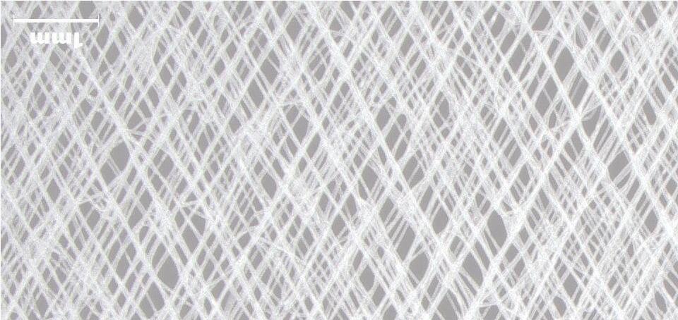
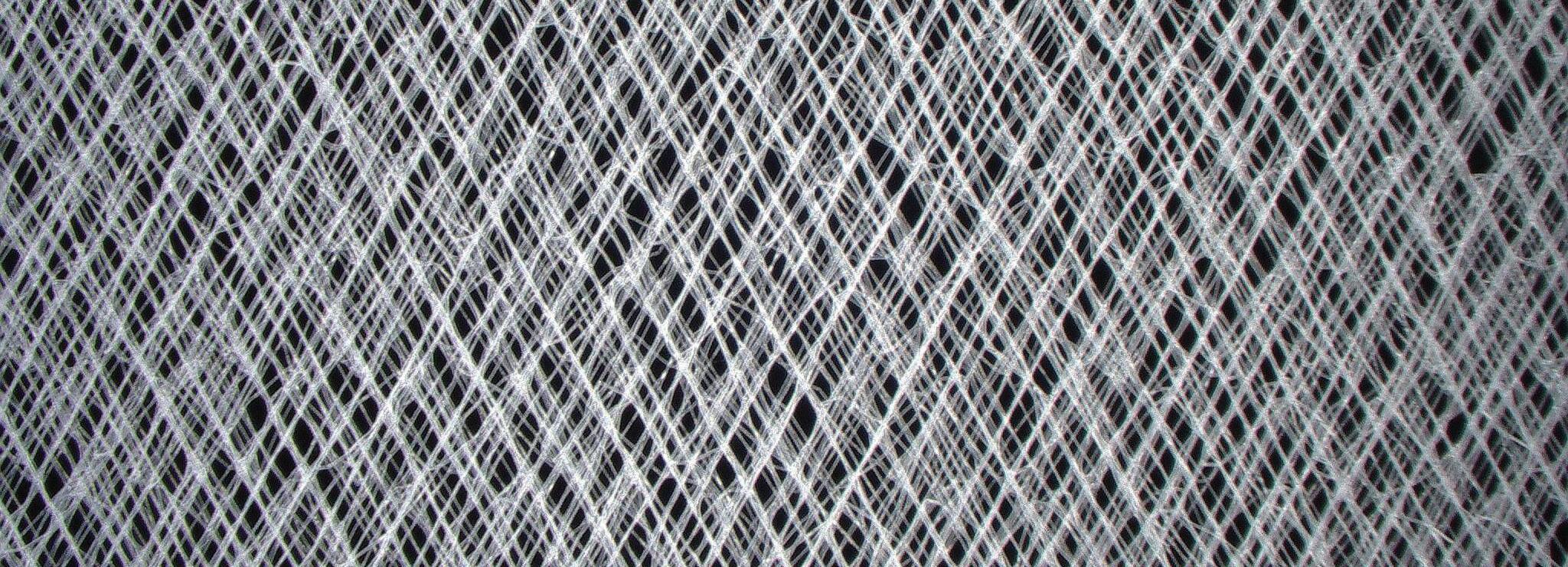
Plant cells inspired a very uniform geometric pattern. Since we are using printing methods that cells can grow on I thought it would be fitting to replicate the cells in the pattern.
The speed for this print was F600.
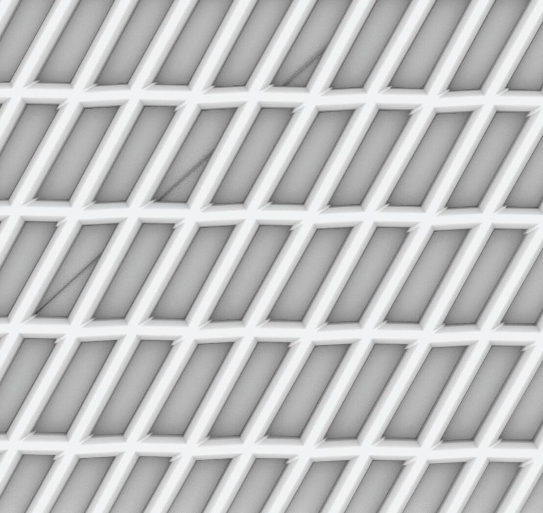
1.28 MM

Microspoic View of Plant Cells
Cartoon of Plant Cells
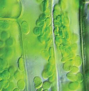
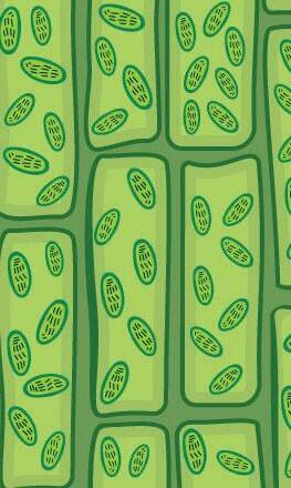
COLLENCHYMA TISSUE
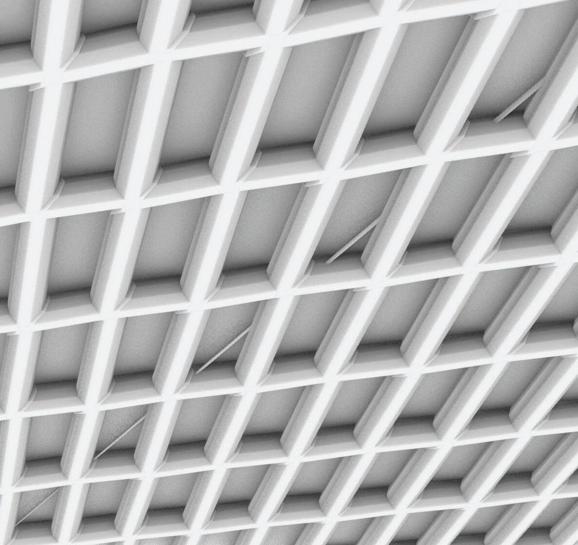
Using insporation from plant structure cells to create a geometric pattern. Once again drawing inspiration from cell shapes and their structure.
The speed for this print was F600
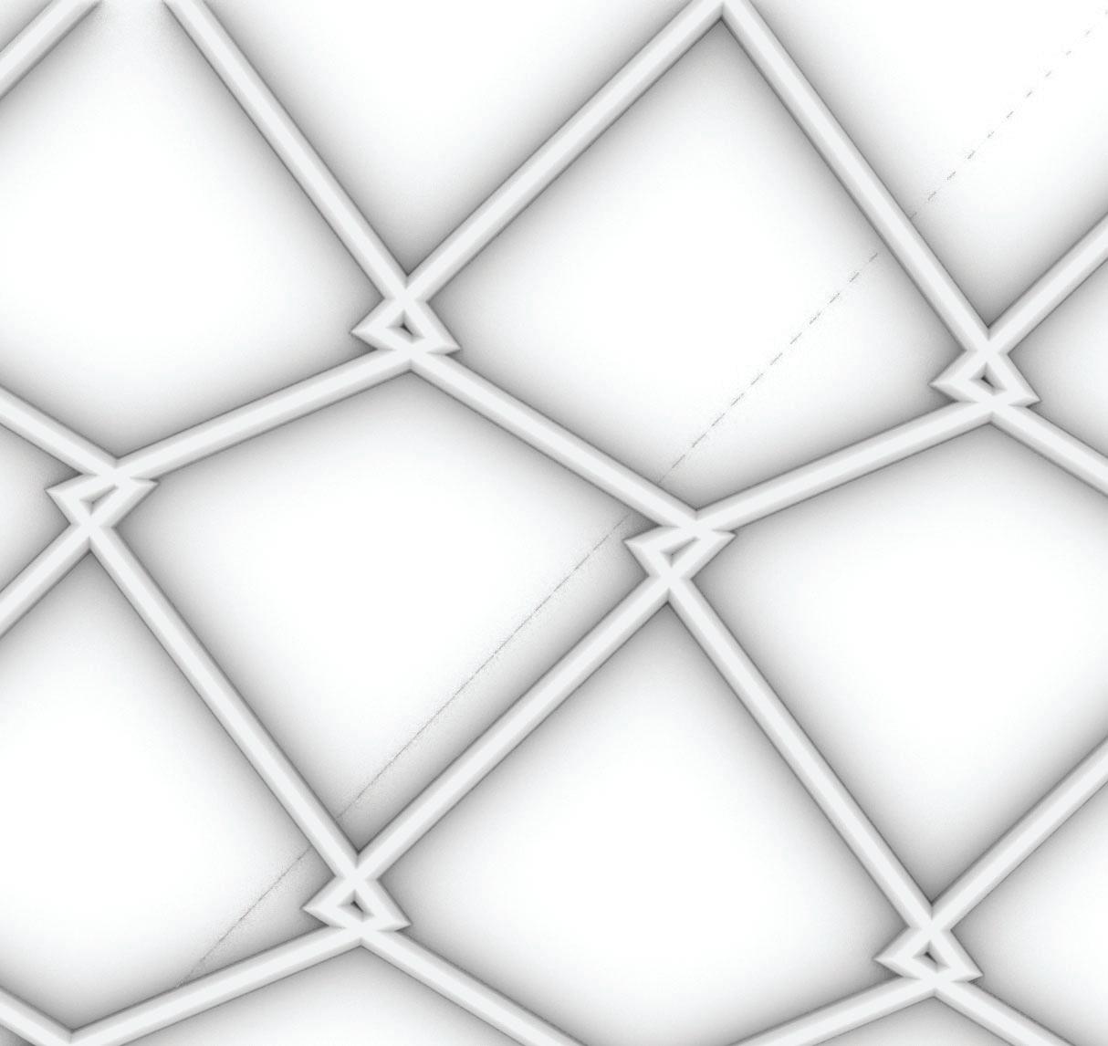

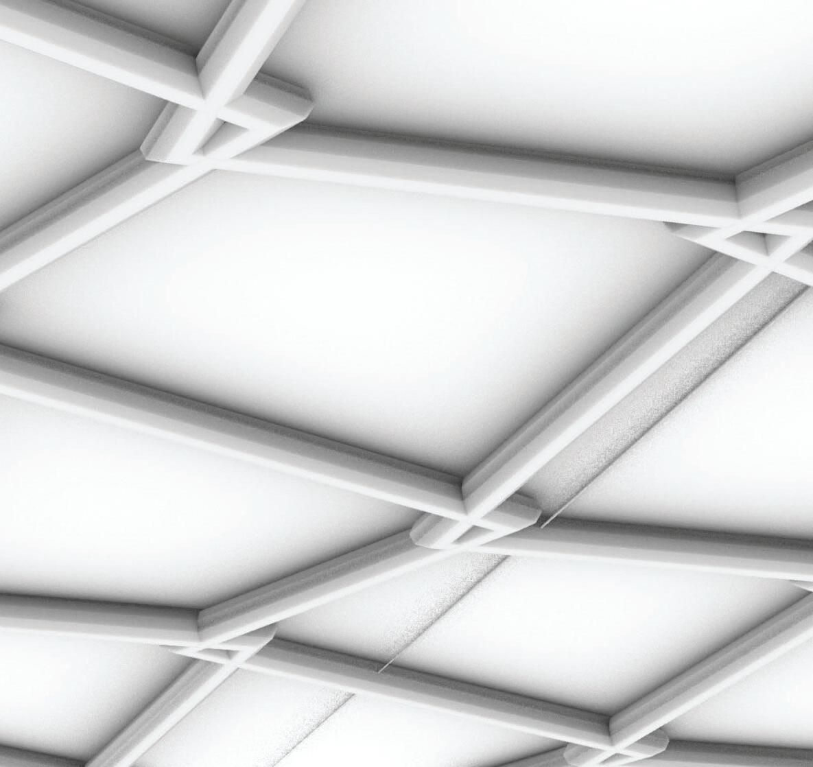
IMAGE: Collenchyma Cells
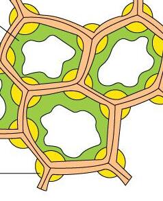
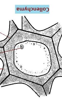
PLANT CELLS
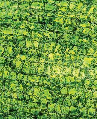
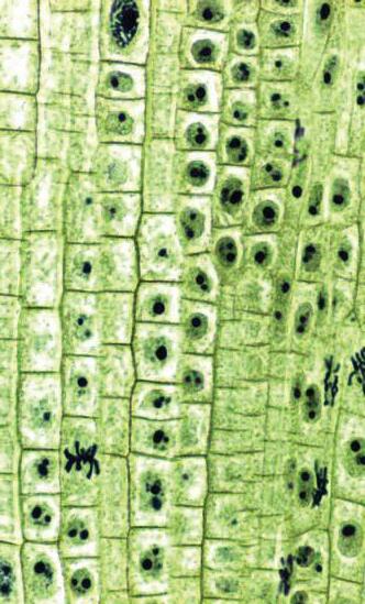
Looking at the alignment of plant cells and trying to print at a slower speed to see the differnt effects that speed have on stright lines.
The speed for this print was F200.
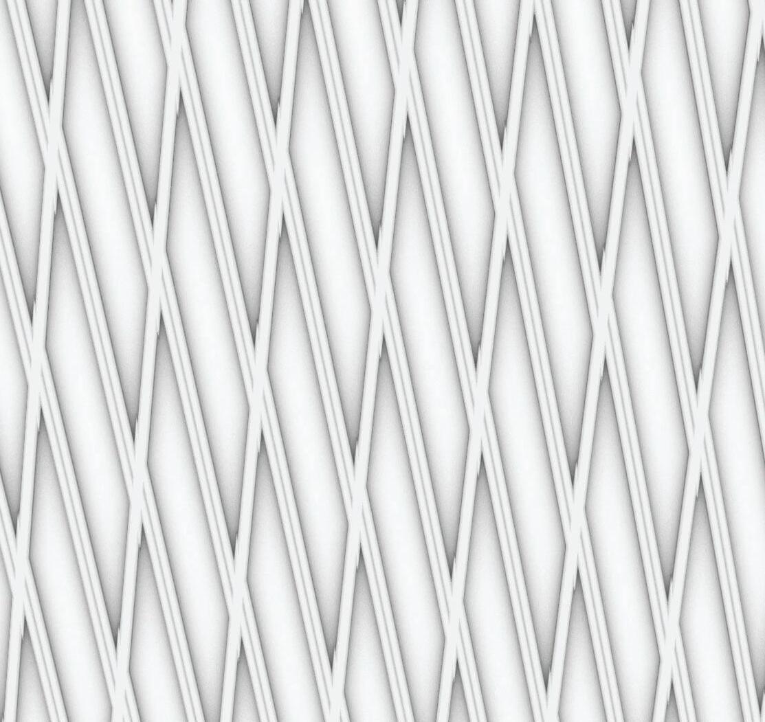
Microscopic View of Plant Cells
LEAF STRUCTURE
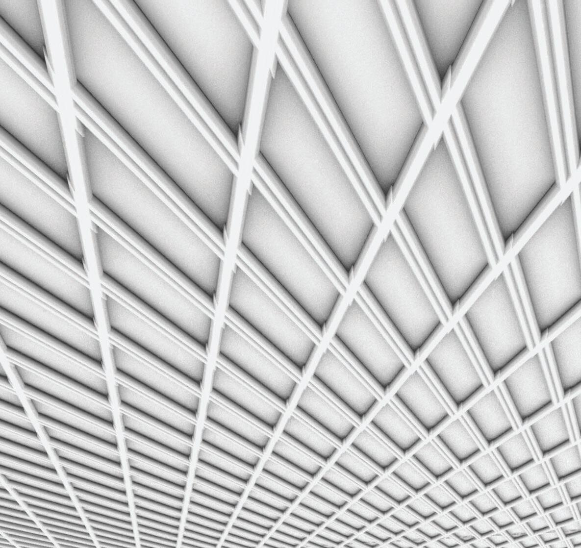
My inspiration was the layering of a leaf structure and the differing layers within it. This pattern has reliefs in densitiy allowing for a varrying amount of ways that roots could interact with the scaffold. The speed for this print was F600
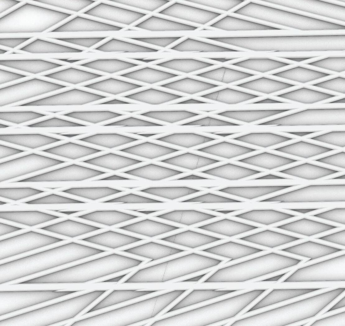

IMAGE:
Leaf Structure Perspective
Leaf Structure Section
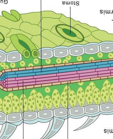
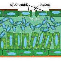
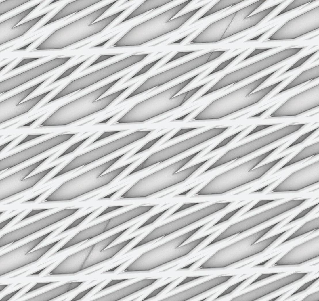
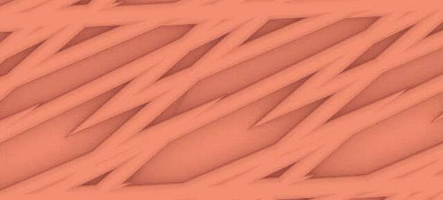
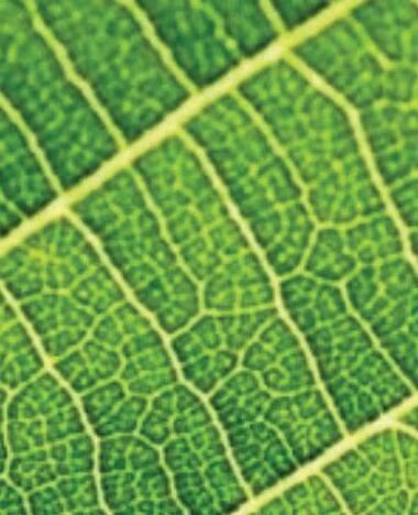
The back of a leaf was the inspiration for this pattern as the differing cell sizes and larger veins create for an interesting look.
The speed for this print was F600.
3MM

IMAGE: Back of Leaf Up Close Back of Leaf

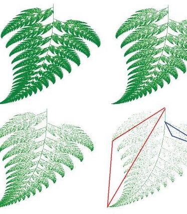
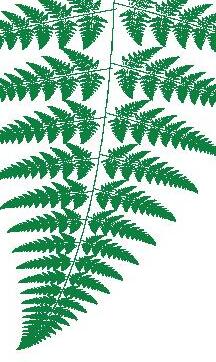
The Bansley Fern is a naturally occuring fractal which means mathematically generated pattern that can be reproducible. This pattern is inspired by that fractal and the triangles within it.
The speed for this print was F600.



Barnsley Fern Fractal Illustartion of Barnsley Fern
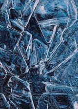
Insspired by the jagged breaking of ice this pattern crosses together with sharp geometric edges.
The speed for this print was F600.


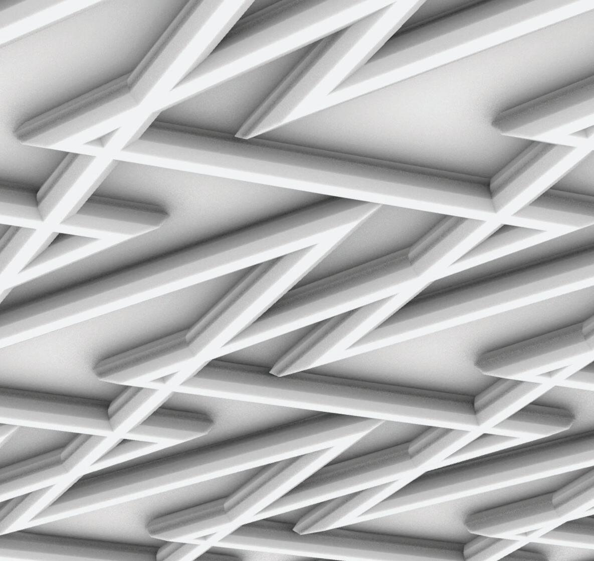

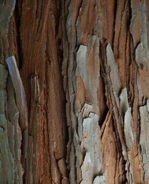
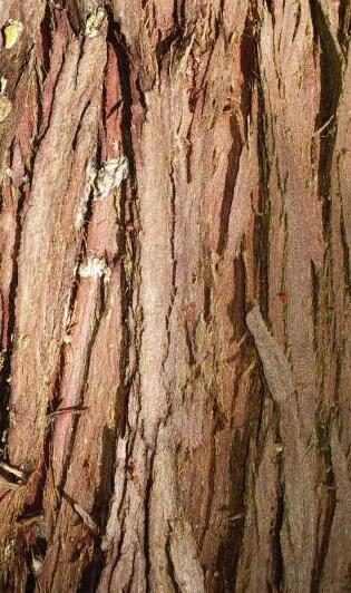
Drawing inspiration from the base of a tree, this pattern is composed of strong lines with a series of lines to connect and fill the space between.
The speed for this print was F600.


COMPUTER VS PRINT
After formulating patterns we chose a couple to test print to help inform which pattern we would ultimately chose for our larger scaffold print. Through these trials I was able to discover slower printing speeds will effect the patterns appearance greatly and the need for overlap within the design.
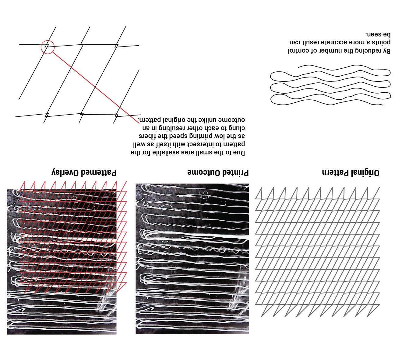
Plant Cell Pattern Print Results
Collenchyma Cells Print Results

CHOSEN PATTERN
After the test prints one presented itself as strong viable option. Drawing inspiration from the Barnsley Fern, a repeating triangle pattern was formed. This is advantageous to our studies as I was most interested in growing moss and the dense pattern would be able to retain water.

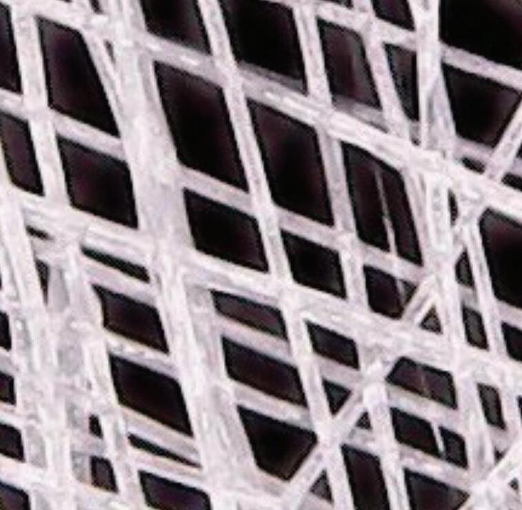
Computer Render of Chosen Pattern
Test Print of Pattern
3D Print of Pattern

CHOSEN PATTERN
After the test prints one presented itself as strong viable option. Drawing inspiration from the Barnsley Fern, a repeating triangle pattern was formed. This is advantageous to our studies as I was most interested in growing moss and the dense pattern would be able to retain water.

Chia Seeds Planted in Scaffold Final 90x90mm Print of Scaffold

LAWRENCE INSTALLATION LOCATION
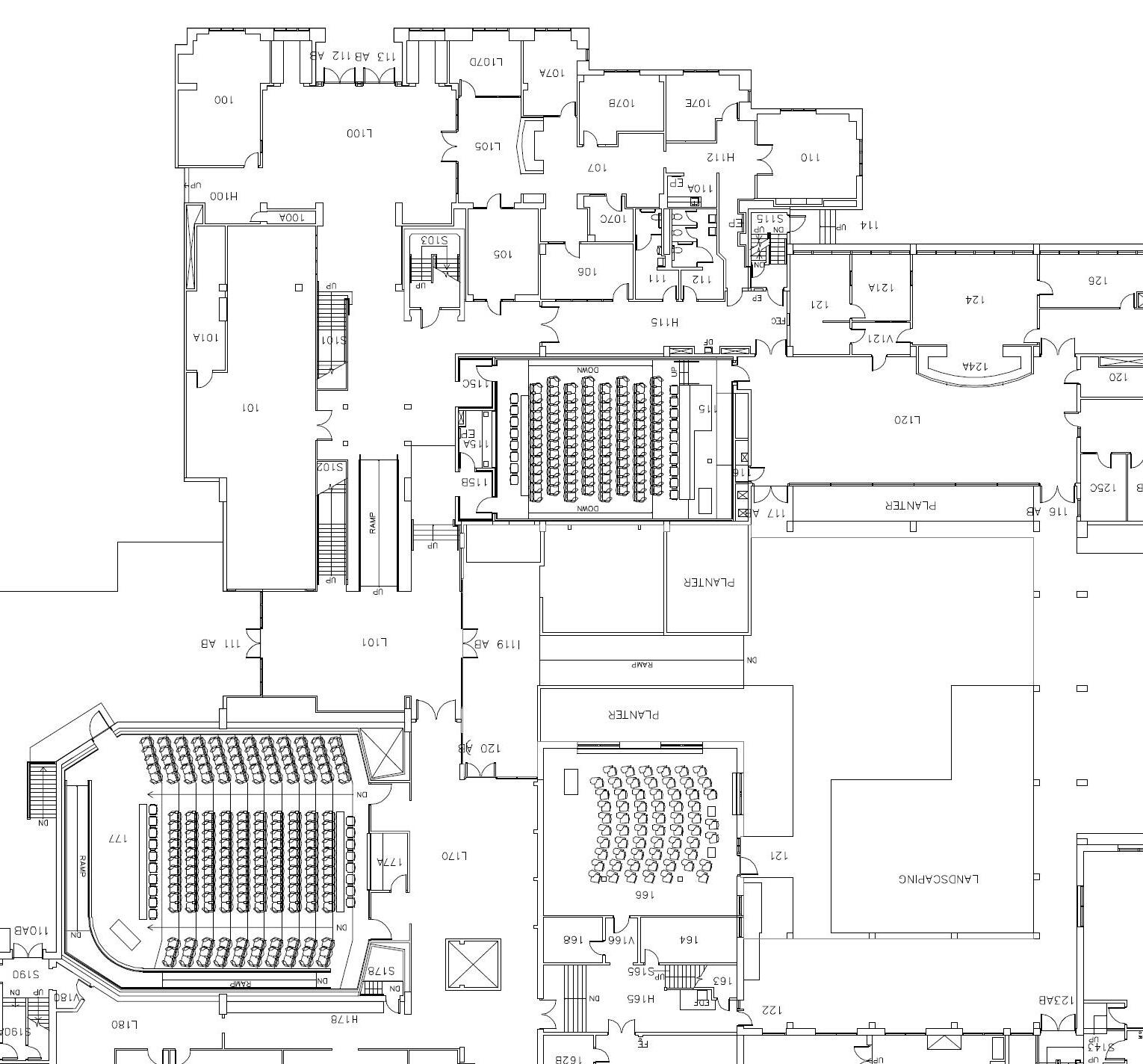
Our first step in our design process was to choose a location in Lawrence to place our living system. I chose the area across from classroom 177 because it is a large lecture hall where a lot of different students pass through. There is also a connection to the courtyard of Lawrence so continuing that indoors with a living system seemed fitting.
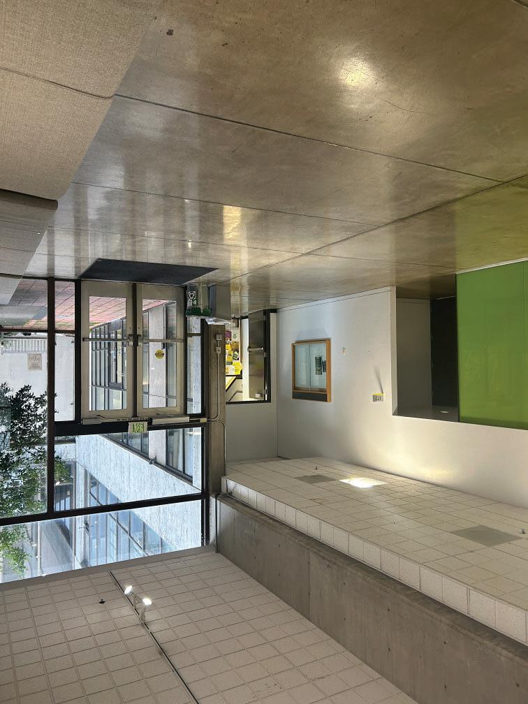
Space Selected for Living System

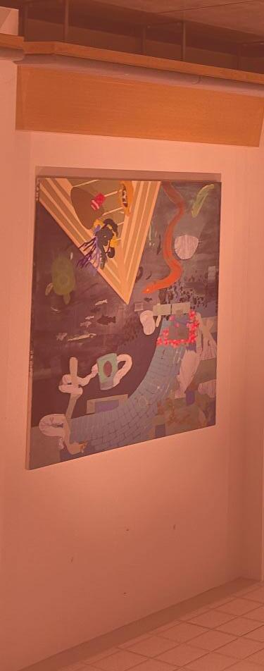
After selecting the space, we used photos of the space to create a digital 3D scan to better understand the space and get dimensional information. Due to lighting conditions and photo quality, the digital scan did not come out complete. Through extracting information from the scan as well as measuring the space, a cleaned up twin of the space was made to make it more ideal for modeling.
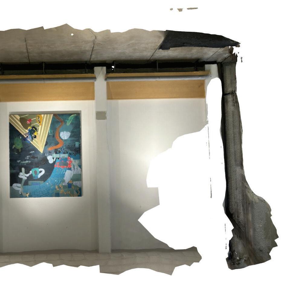
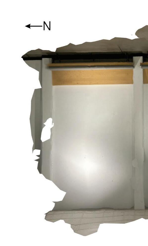
IMAGE:
Lidar Scan of Space Digital Twin of Space
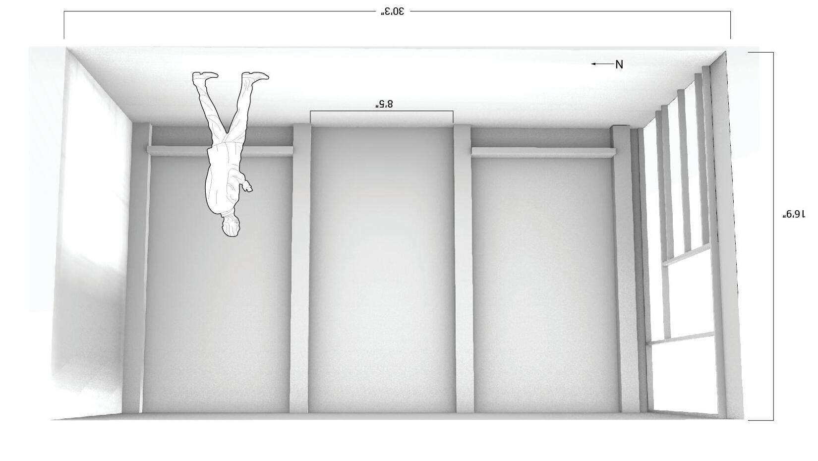
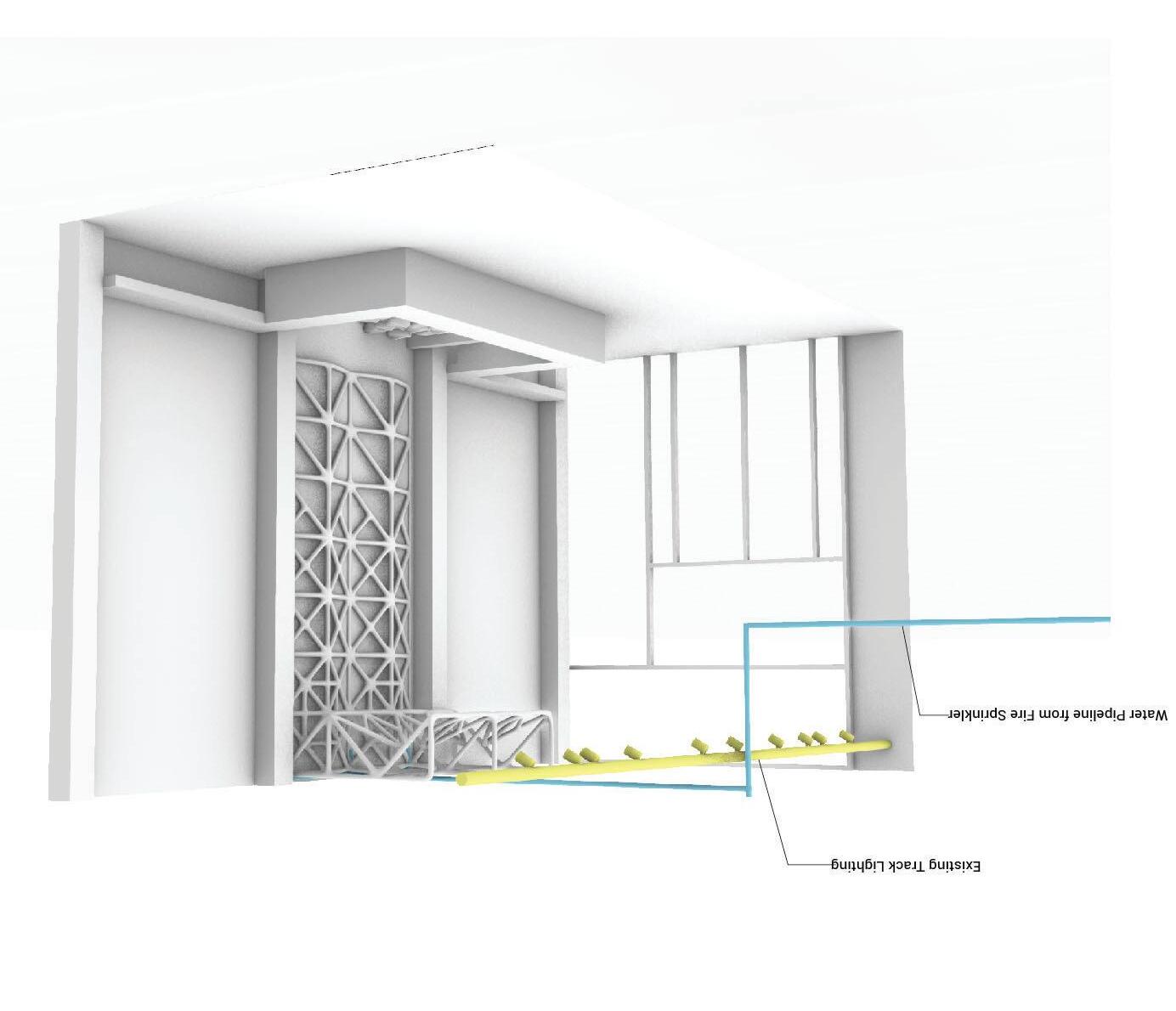
This space offers ample area for the living system to be built and drawn out into the 3D plane. This space has existing systems that can help supply the living system. Trough tapping into the fire sprinkler and track lighting that is already in place, it is able to help support the living system.
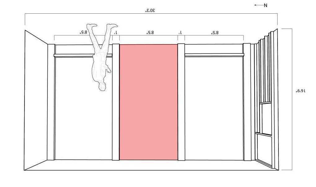
Perspective of Space Drawing Elevations of Space
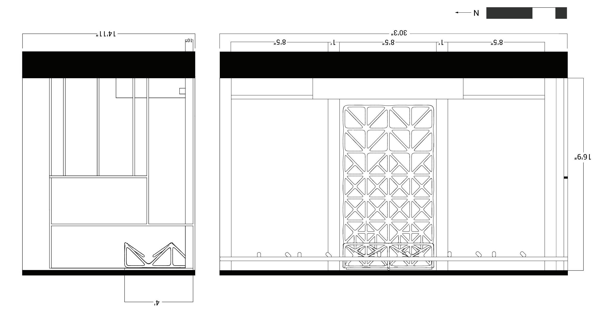
LOCATION IN LAWRENCE
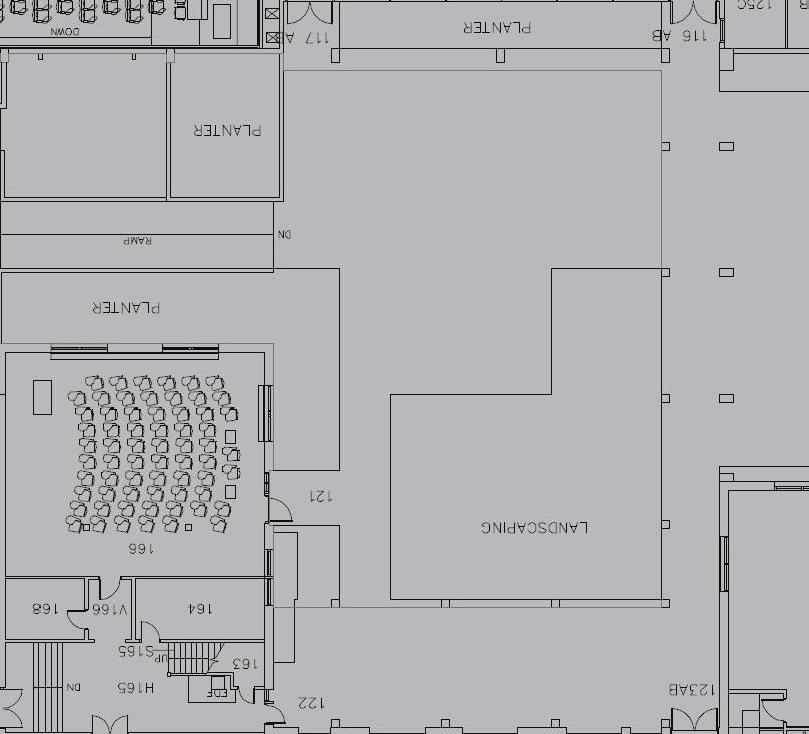
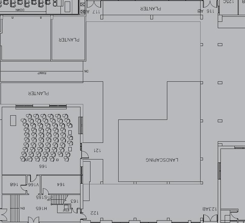
The space I chose is not only in front of a large lecture hall but within the main circulation route of the first floor. It is also next to the courtyard and through this location it is able to continue indoors.
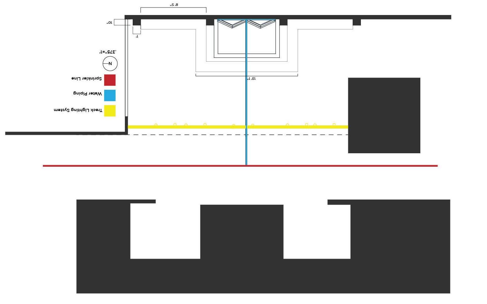
IMAGE:
Plan of Exsisting Systems
Location in Lawrence


BUILDING SYSTEM AXON
After discussing different options for the drainage system and researching how they work, I chose to do a water collection system with a drain pipe at the bottom of the structure. To keep people away from the water collection I added a bench around it to also create extra seating.
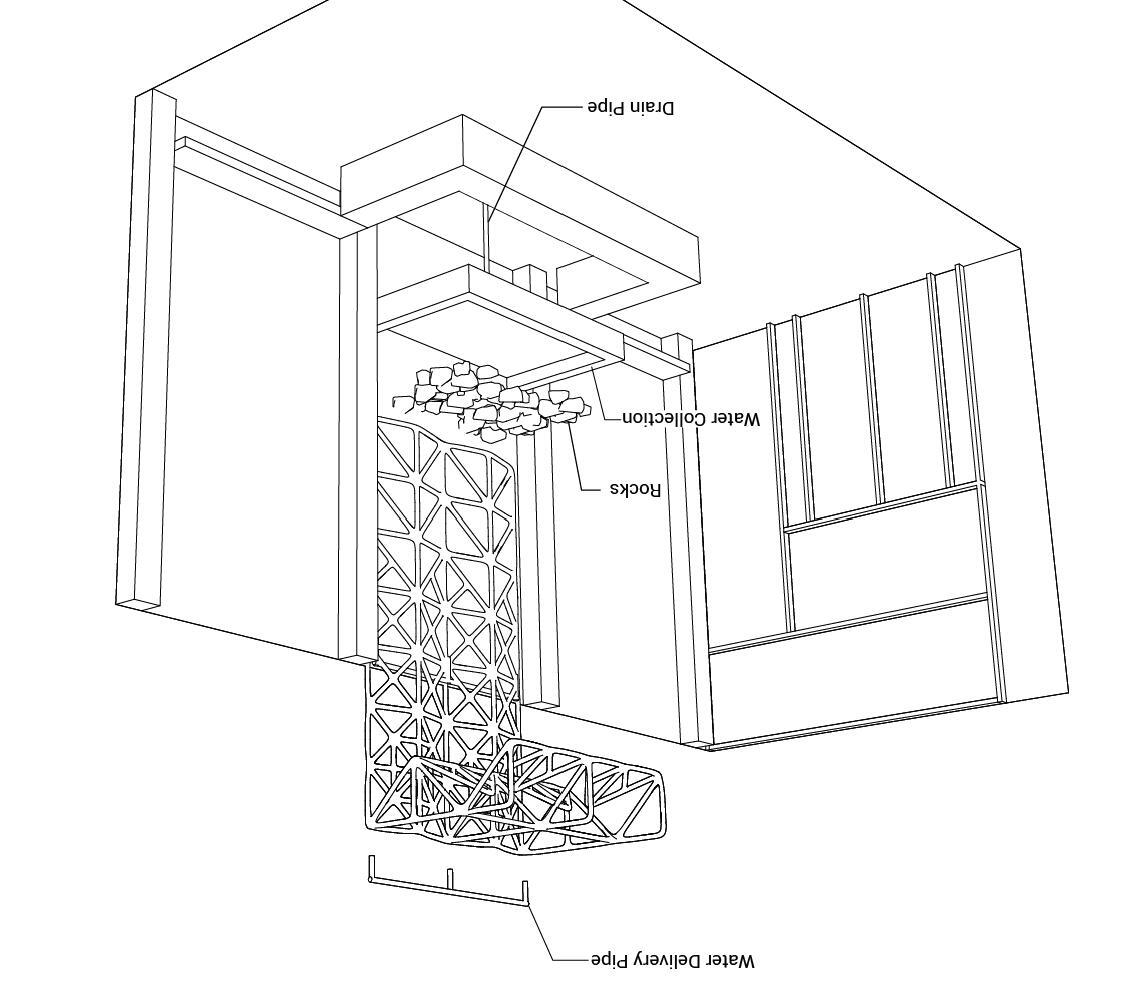
Axon of System
Hooking up to Exsisting Connections
To better understand the growing conditions of my space, we measured light exposure and lux levels. Through a computer generated exposure analysis we can see that the space does not receive much daylight and will need supplemental light for the plants to grow. This is confirmed with the lux levels that were measured in the space.
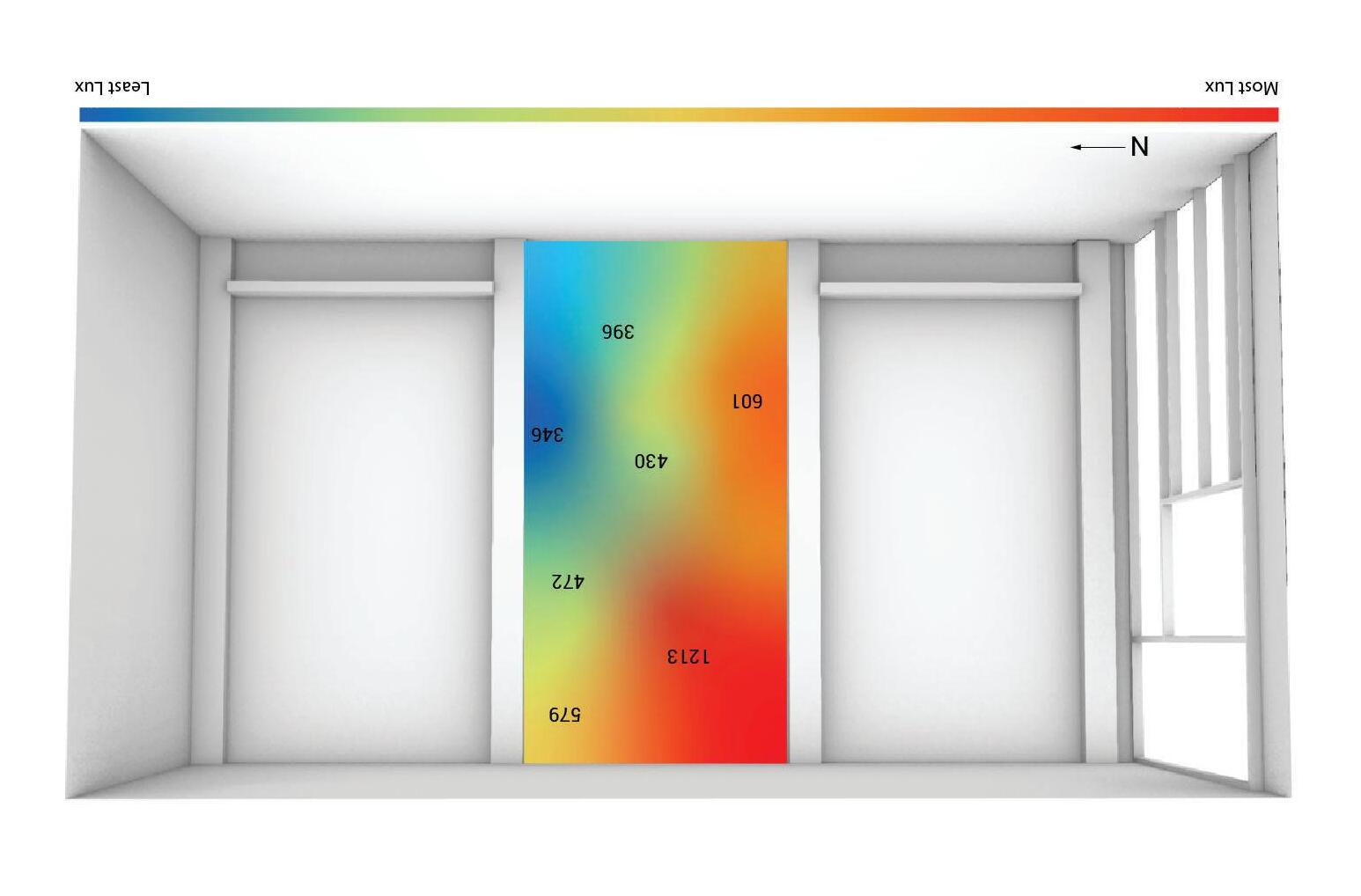
LEAST EXPOSURE
Lux Levels Taken on February 15, 2023 at 1:30PM
Annual Exposure
MOST EXPOSURE
SCAFFOLD STUDIES
Through spatial analysis we looked at developing different patterns for our green wall. I chose a pattern that would reflect the same qualities as by scaffold pattern with repeating triangles. As well, as playing with three-dimensionality and density.
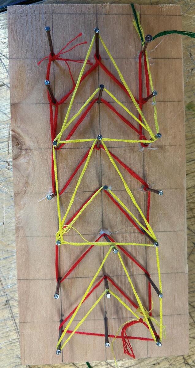
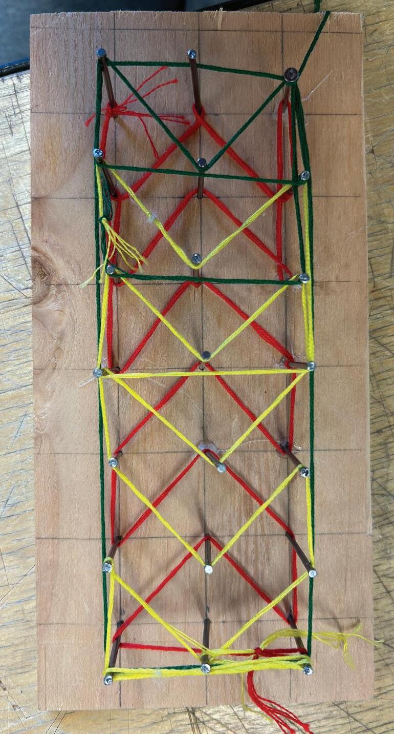
String Pattern Studies
Midterm Proposed Pattern


WATER FLOW
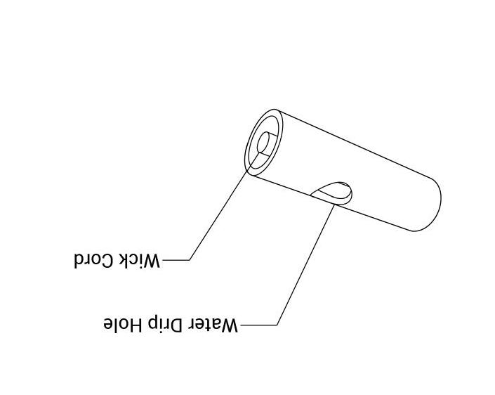
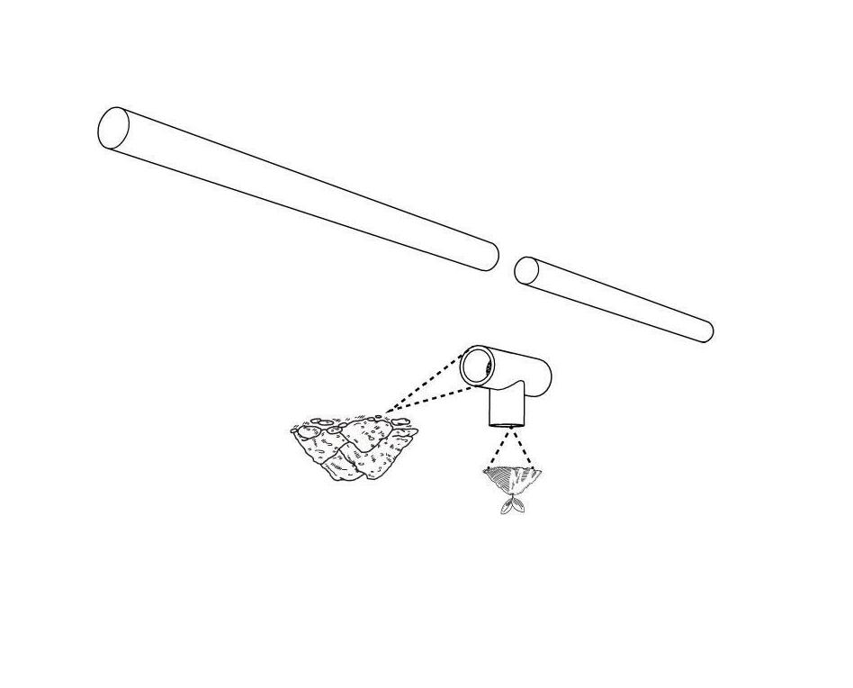
The water flows through punctures in the piping and is distributed throughout out the structure. Due to the placements of my plants water is not accessing the plants directly. This is remedied through a wicker system which helps deliver water directly to the plants.

IMAGE:
Simulated Water Flow Wick System

PROPOSED PATTERN
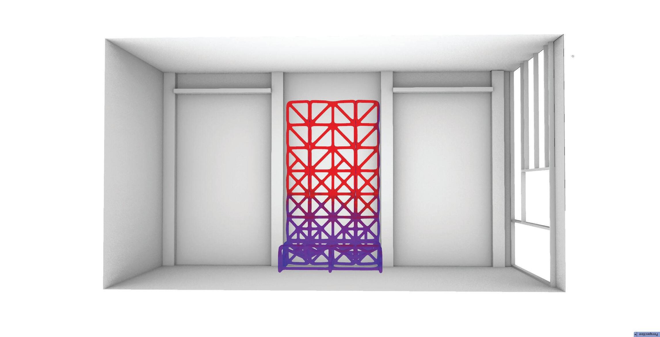
My proposed pattern is drawn from inspiration of my MEW scaffold print as well as informed by my previous studies during midterms. Playing with changes in density as well as three-dimentionality were some of the goals I wanted to accomplish with my final pattern. Using five different modules was how I accomplished these goals while keeping the design simple and repplicable.

Final Pattern Rolled Out and Modules Used
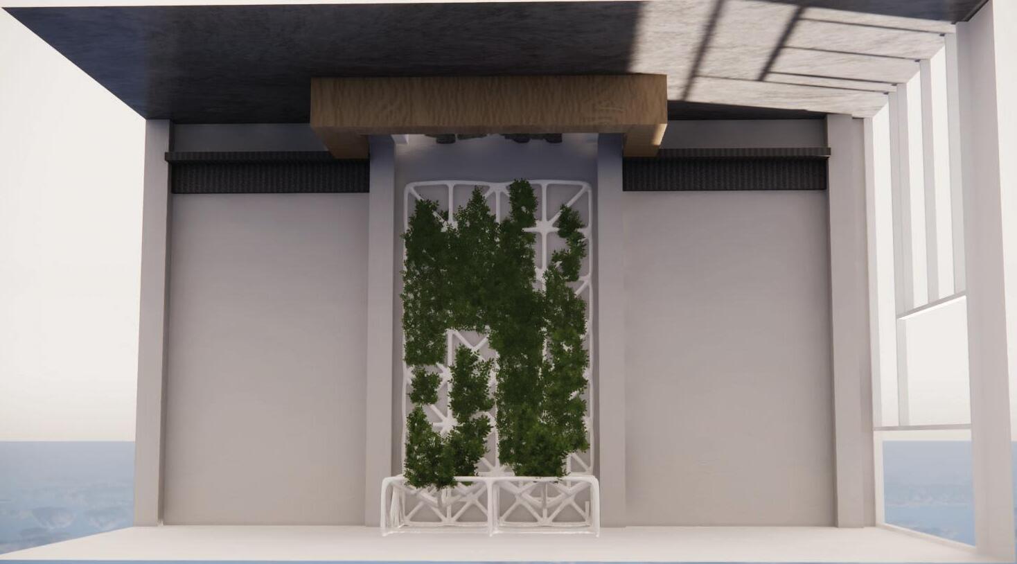
Final Pattern in Space

Through the lux and light exposure analysis the lack, we can see the lack of light that the space receives. This informed my plant selection as I chose one’s that require low light needs in order to thrive. My plants go along the center of each module and conatin one of three different plants. The plants I chose have low lighting needs but after calculation of the avalible light in the space supplemental lighting will still be needed in order for the plants to thrive.




Plant Locations on Living System
Species Placement on Wall


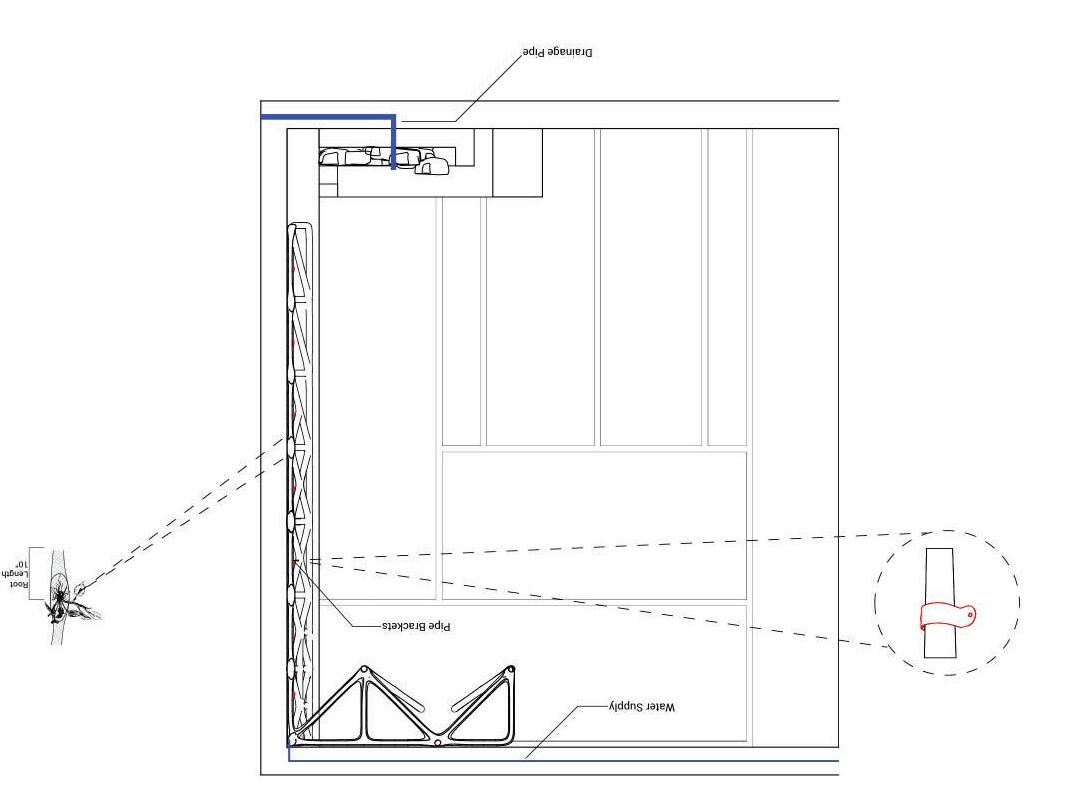
The living system is to be installed using a series of brackets on the wall and along the ceiling. In each module there is a point of connection with the wall or ceiling. At these points a bracket will be used to secure it to the wall.

Bracket Placement
Wall Section
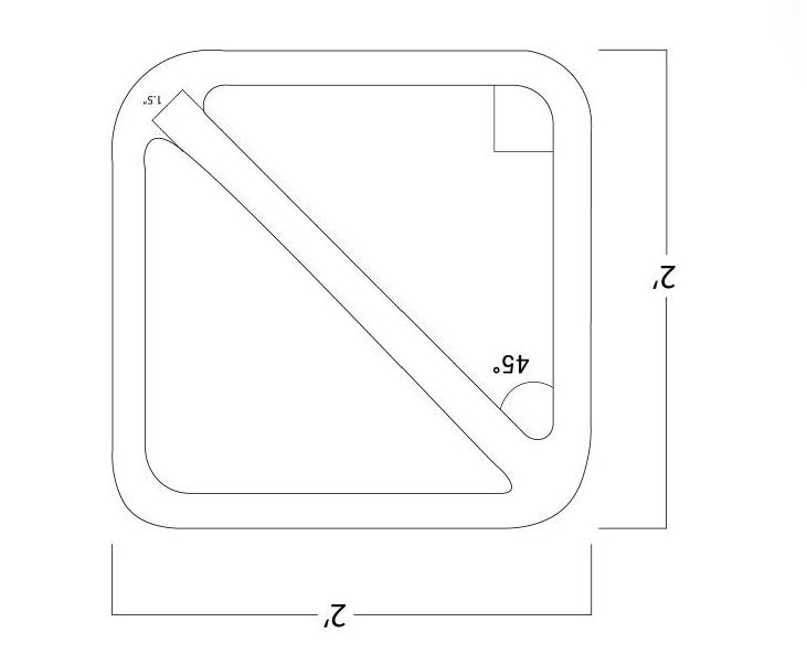
SELECTED BUILDING MODULE
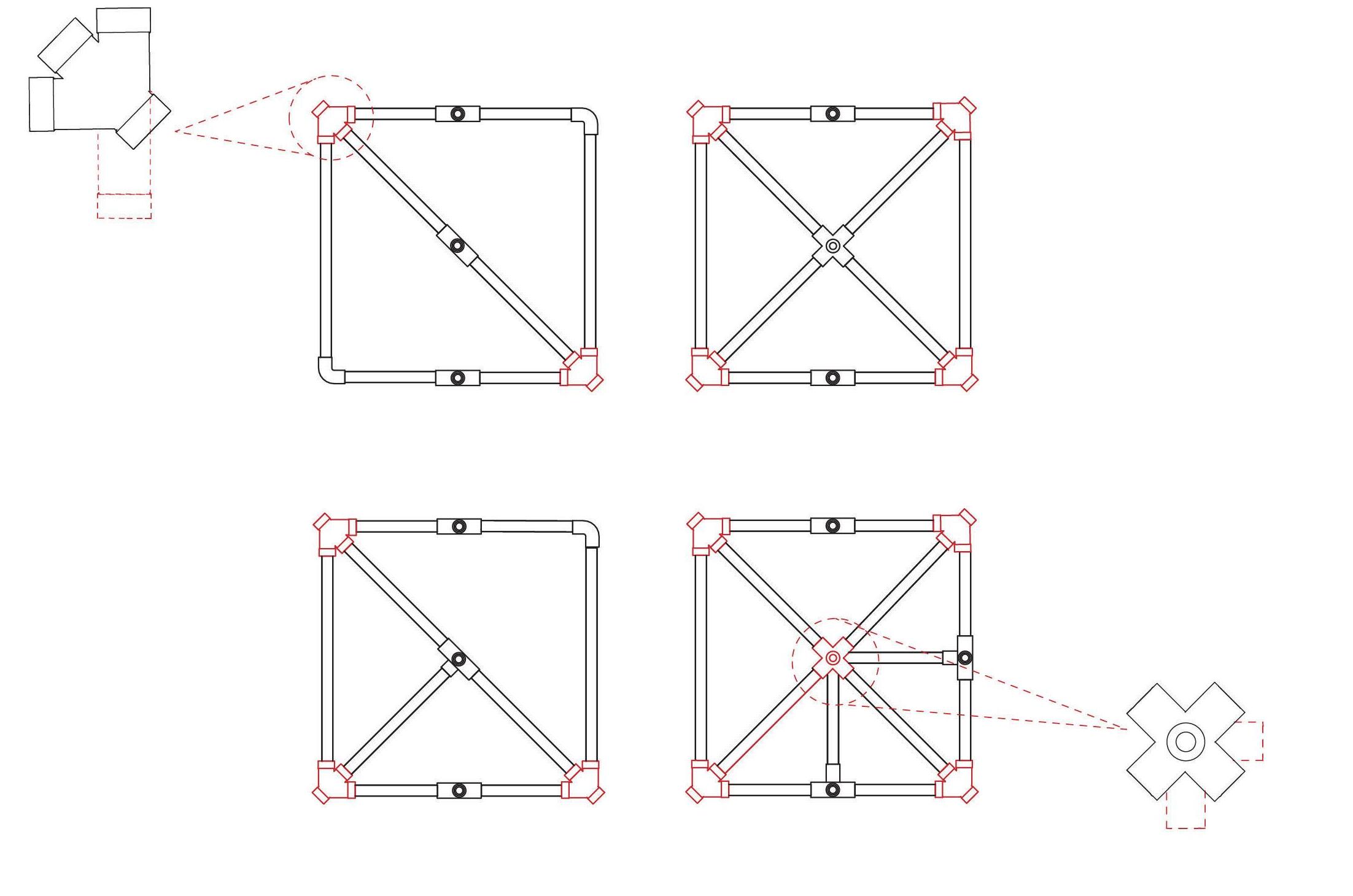
I chose to construct the bottom module of my system because it is the building block for the rest of my modules. Through looking at what was accessible to purchase I used three different PVC fittings to create the module.



Area Selected to Prototype Work Progress of Connections Available Drawing of Connections used to Create Prototype

COMPUTER VS REALITY
While the pieces available to purchase created the module itself the connection points was not able to be replicated. One of the largest issues was the 45 degree angles as there were few products avalible to create it. Using a Wye connection it almost replicates the needed result but instead of the corner going out in a 45 degree it would need to be a 90 degree to allow for a connection to the module above.

Wye Connection Issue Issues in Other Module Connection
BUILT MODULE
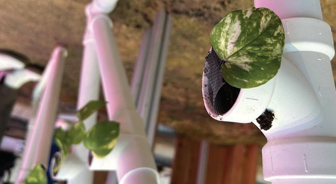
While the pieces available to purchase created the module itself the connection points was not able to be replicated. After building the prototype I planted in a pothos and chia seeds in soil. The plants were regularly watered everyday and were in the greenhouse for a week to allow for ample growth.

Prototype with Plants Inside Perspective of Prototype
With these four modules we are able to utilize them in different ways. One looking at a horticultural perspective. Through using the modules farmers or nurseries could plant vertically and use these structures to allow for sapplings develop. Since the modules are a simple square it could be used for building outdoor structures allowing for outdoor shading. Since these applications are outdoors, it would allow for these systems to be free of supplemental systems either being watered by rain or someone watering it with a hose.
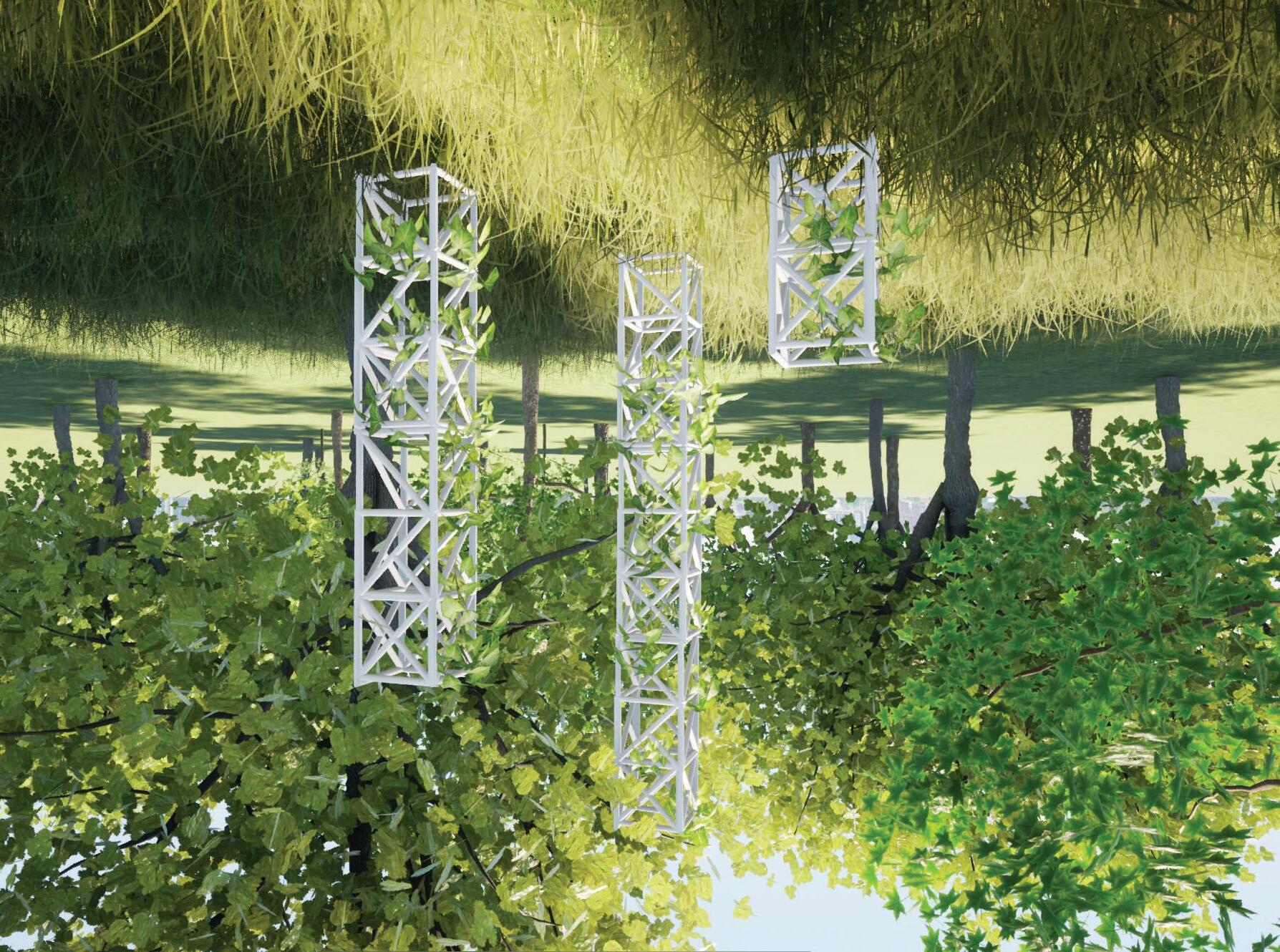
IMAGE:
Horticultural Application
Structure Application

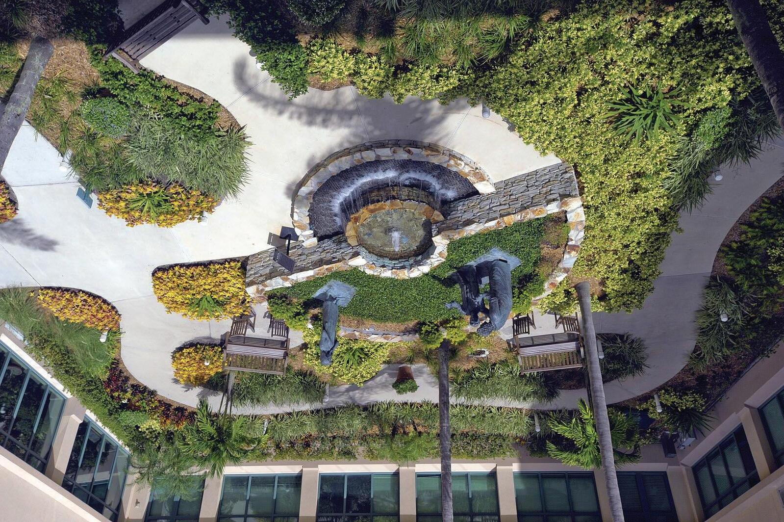
There have been many studies looking at the importance of greenery in healing process as well as natural sounds. Looking at how both these could be offered to help expedite the healing process would be an application useful beyond Lawrence. There have been many studies proving that patients recovering from surgery with plants in their room experience lower blood pressure, lower levels of pain, anxiety, and fatigue. Through using the living system developed it can be used to assist patients so they can receive these benefits. The system would be installed similarly to the one in Lawrence with water being received at the top of the system allowing for the water to trickle into a shallow pond creating a more sensory driven experience.
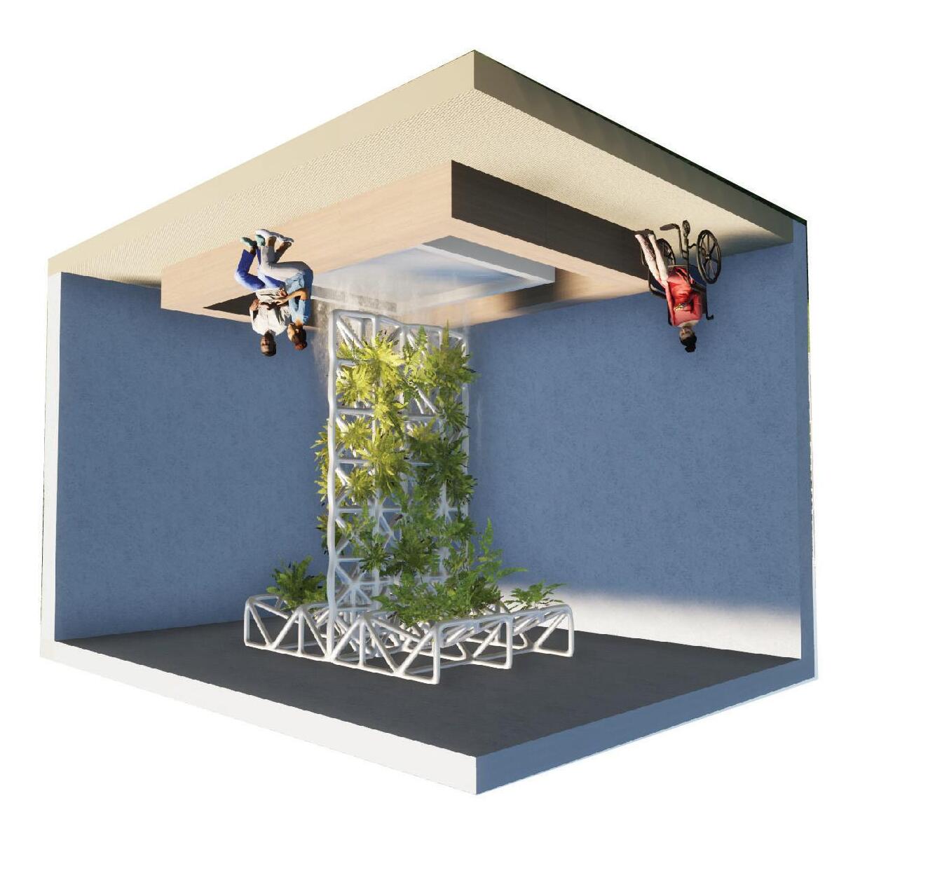
IMAGE:
Living System Health Care Application
Healing Garden at Advent Health
SIZING, OPENINGS, AND MATERIALITY
Another possibility for a different type of plant opening would be to cut out portions of the PVC pipe on the horizontal parts of each module allowing for a larger opening.
Since each module is fairly simple it could be scaled up or down for different uses. Currently the modules are 2’x2’ with a width of 1.5” for the pipes.
In the spirit of Pompidou, using acrylic tubing to expose the plant growth and growing media inside the tubes would add to the aesthetics of the structure.
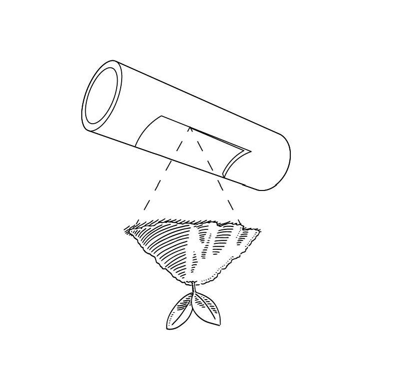

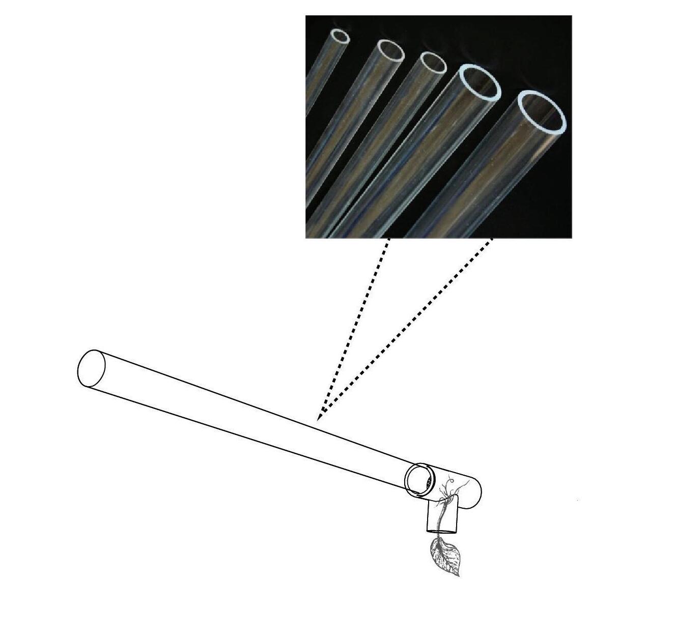
Different Opening and Placements Different Materiality
VR CAPTURES
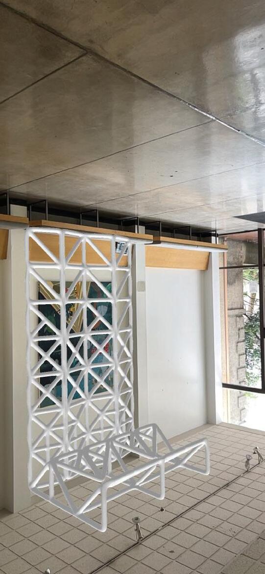
Using VR, we are able to see what the system will look like in place at Lawrence Hall. Through this we can see how the structure will interact with the space on a tree-dimentional level and better understand how it interacts with the space.
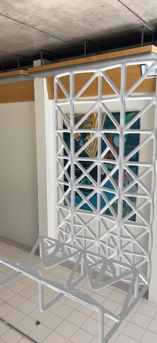
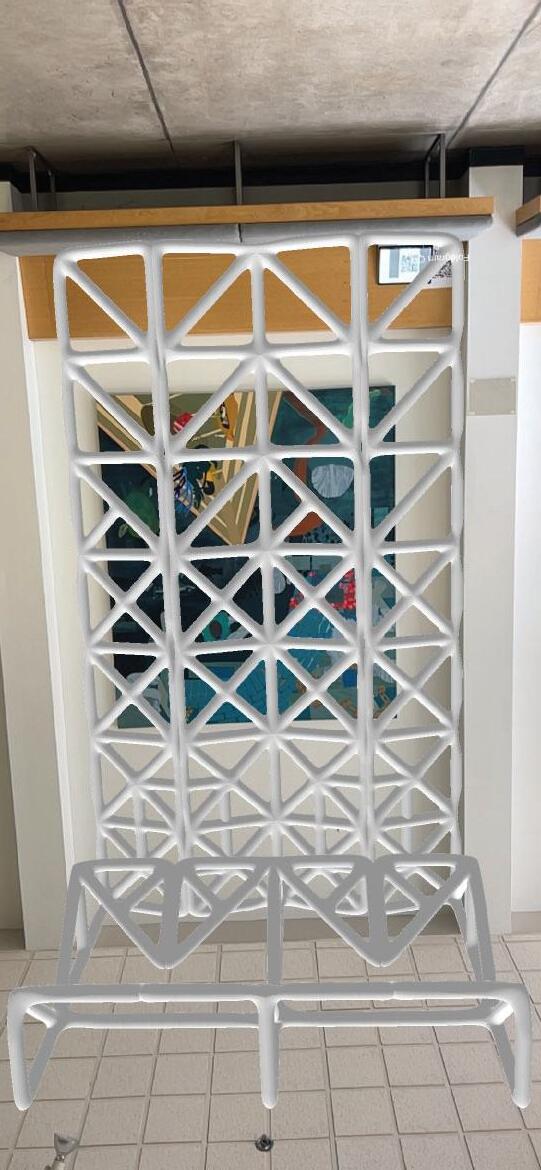
VR Captures of Structure in Lawrence

3D PRINT
Through the Knight Campus, we were able to 3D print our final designs and see what they would look like on a smaller scale. It also helped better visualize the space by putting it into our model of the space.

IMAGE: 3D Print

MODEL OF THE SPACE
Building out the space in 1/2” scale we were able to test different patterns and see how they interacted with the space.
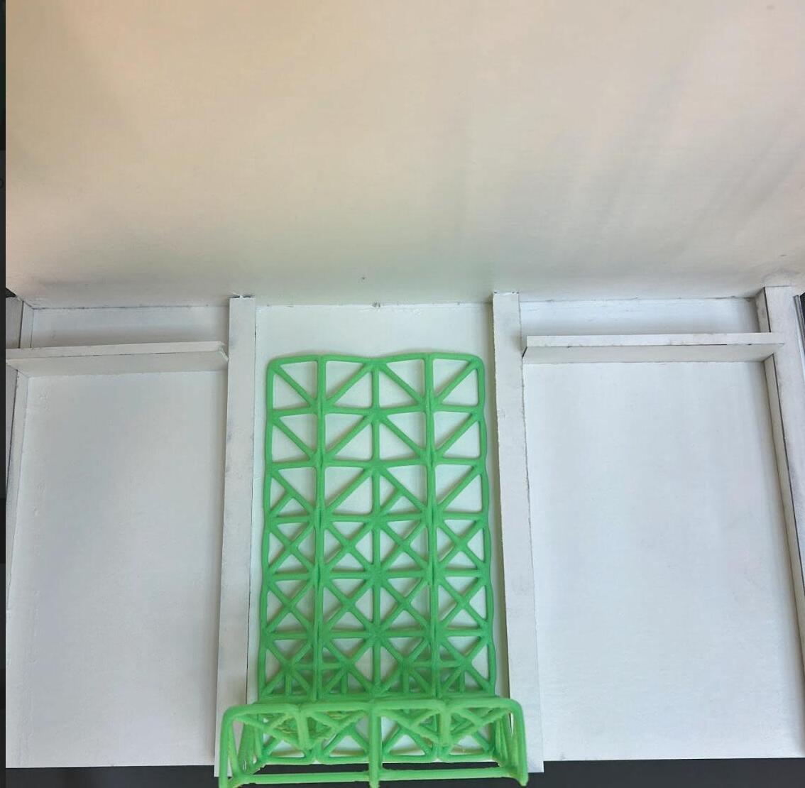

IMAGE: 3D Print in Model
FINAL PROTOTYPE
Using the products that were avalible on the market I was able to assemble something fairly similar to my desired results. The two modules are connected through zipties but in actuality they would be connected with brackets and the same issue mentioned earlier with the Wye not being at the correct angle would also need to be adjusted.
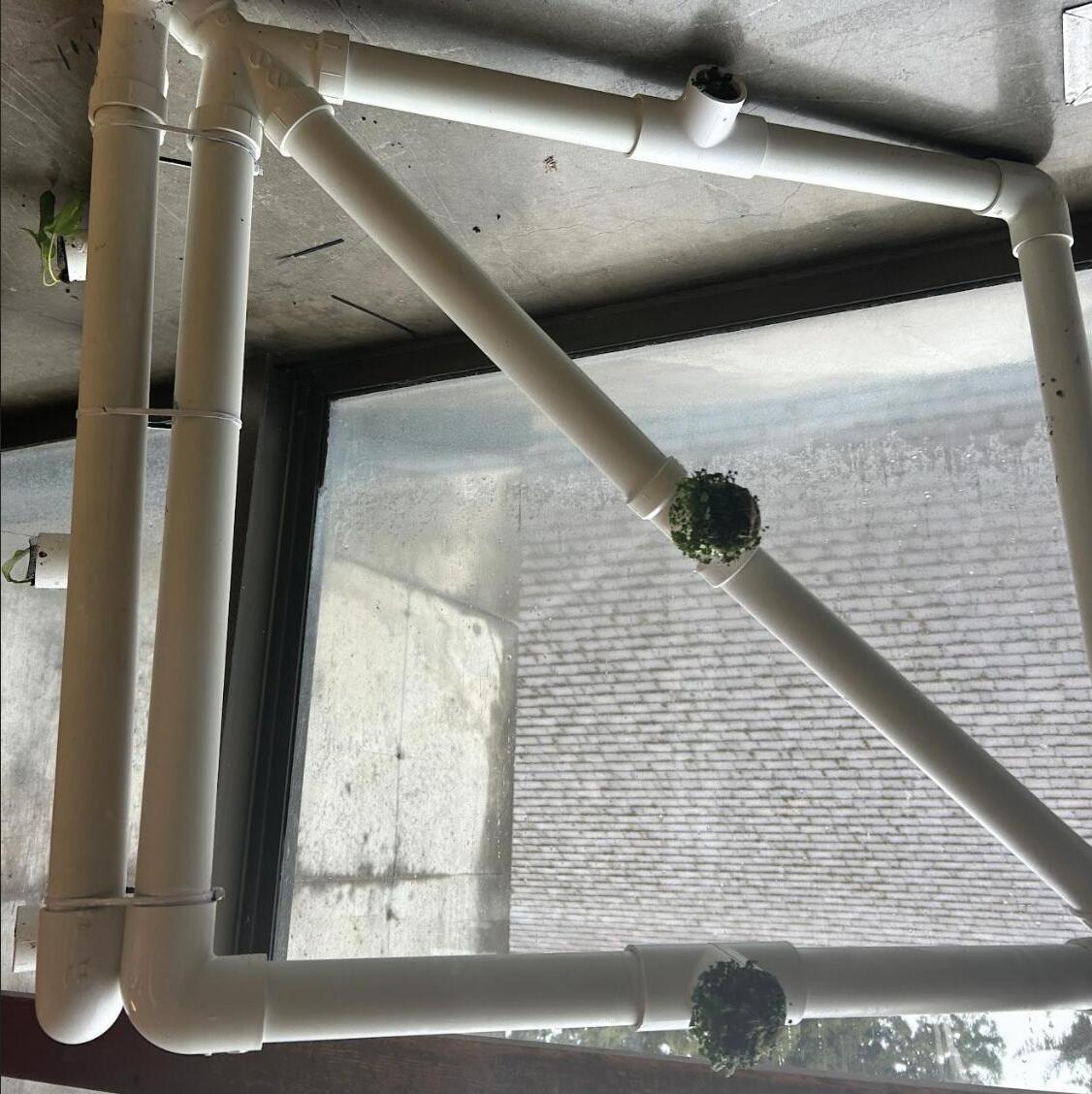
IMAGE:
Prototype Assembled

It has been an interesting journey playing with plant life at different scales and how we can best facilitate growth. Through this course I was able to find a deeper understanding of the fabrication process as well as looking at living systems beyond aesthetic purposes. At the beginning of the studio I understood green walls to be something I added on to make my building appear prettier and more sustainable. Through this course I saw not only myself but as well as my peers finding different applications of these systems and the benefits that came with them. It has lead me to understand the maintance that is required for these systems and the necessary infrastrucure needed to support these living systems. This has inspired me to be more thoughtful about the use of greenery and see beyond aesthetic purposes. This has been a refreshing step back from a traditional studio and being able to dive deeper into one element of design has been incredibly gratifying. Allowing us to explore something on such a deep level will allow me to consider design elements more deeply and what their application could mean for the space.
IMAGE: Scaffold Final Render
THANK YOU!
