


ARCH 484 | WINTER 2023
IAN DAHL

IMAGE: Caption Caption
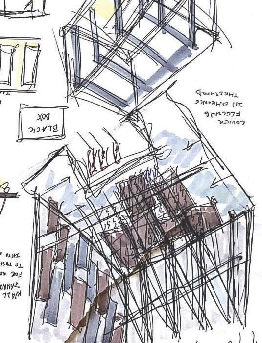
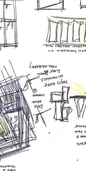


Current third year enrolled at the University of Oregon pursuing a Bachelor in Architecture and a minor in Environmental Humanities. Design works focus on the experience and possibilities of the user within the space, with much of the inspiration of my work drawing both from the beauty of cinema and nature. Cinema and nature offer a unique ethereal experience for the user and ushering that experience is the goal of my designs.
My personal career goals focus on pursuing architecture that contributes to climate justice and environmentally sustainable practices.

EXPLORATION OF PATTERN
FUTURE & FINALIZATION
PROPOSAL POTENTIAL INFRASTRUCTURES
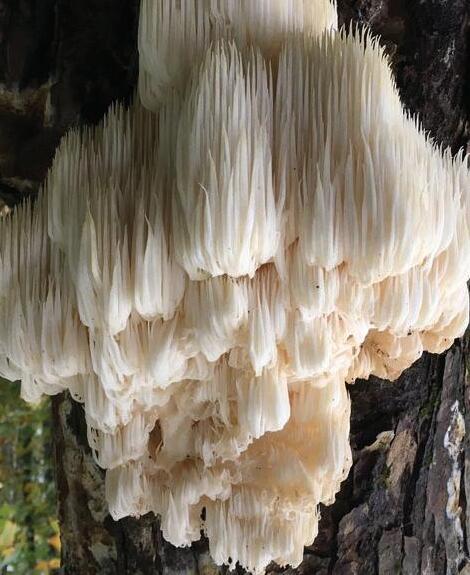
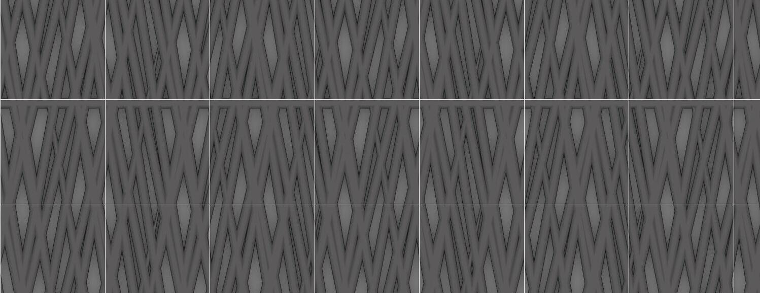
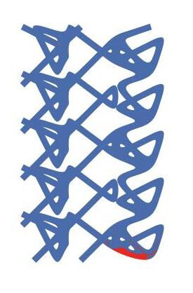
PATTERN 1 | ITERATION 1
This pattern is meant to draw upon the overlapping traingular nature of the bear’s head tooth, with repetition of these elements creating differiential sizings in each unit.
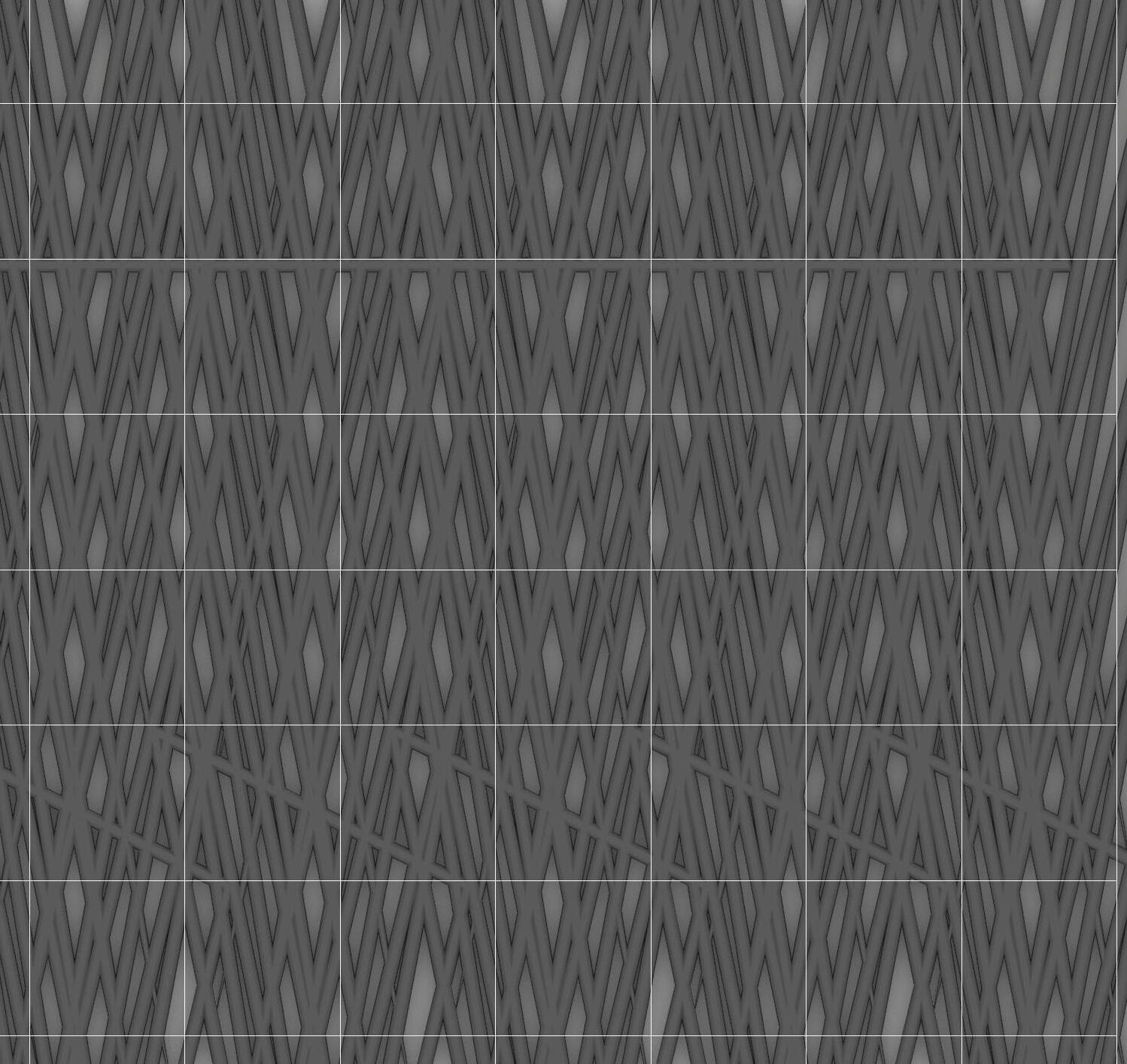

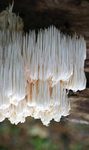
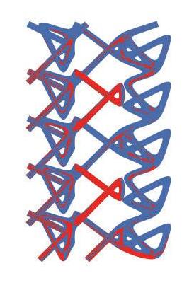
PATTERN 1 | ITERATION 2
This pattern is meant to draw upon the overlapping triangular nature of the bear’s tooth, reflecting the compactness of the development of the bear’s head tooth growth.

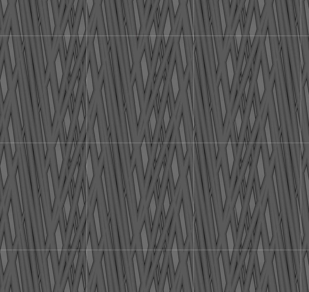


PATTERN 1 | ITERATION 3
This pattern is meant to draw upon the overlapping triangular nature of the bear’s tooth and the density of the mushroom through the concentration of the strokes.

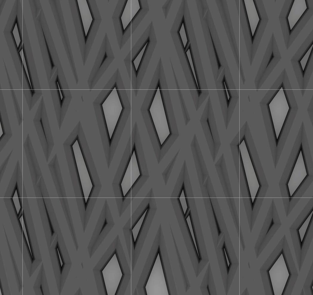


PATTERN 2 | ITERATION 1
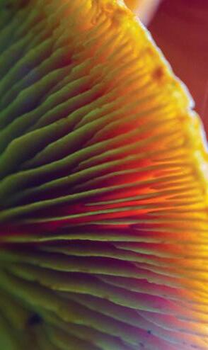
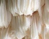
This pattern is meant to reflect the vertical nature of the gills on the cantarelle, with the low density areas meant to imitate the void space between each gill.


PATTERN 2 | ITERATION 2
This pattern is to develop in the same shape as the chantarelle mushroom, starting with a narrow base and eventually flaring out into a wide cap.


PATTERN 2 | ITERATION 3
This pattern is to develop in the same shape as the chantarelle mushroom and reflect its flared verticality in the gills.


PATTERN 3 | ITERATION 1
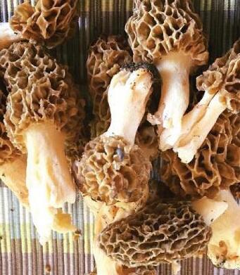
This pattern is to take inspiration from the honeycomb like nature of the morel cap with varying densities in the shape.



PATTERN 3 | ITERATION 2
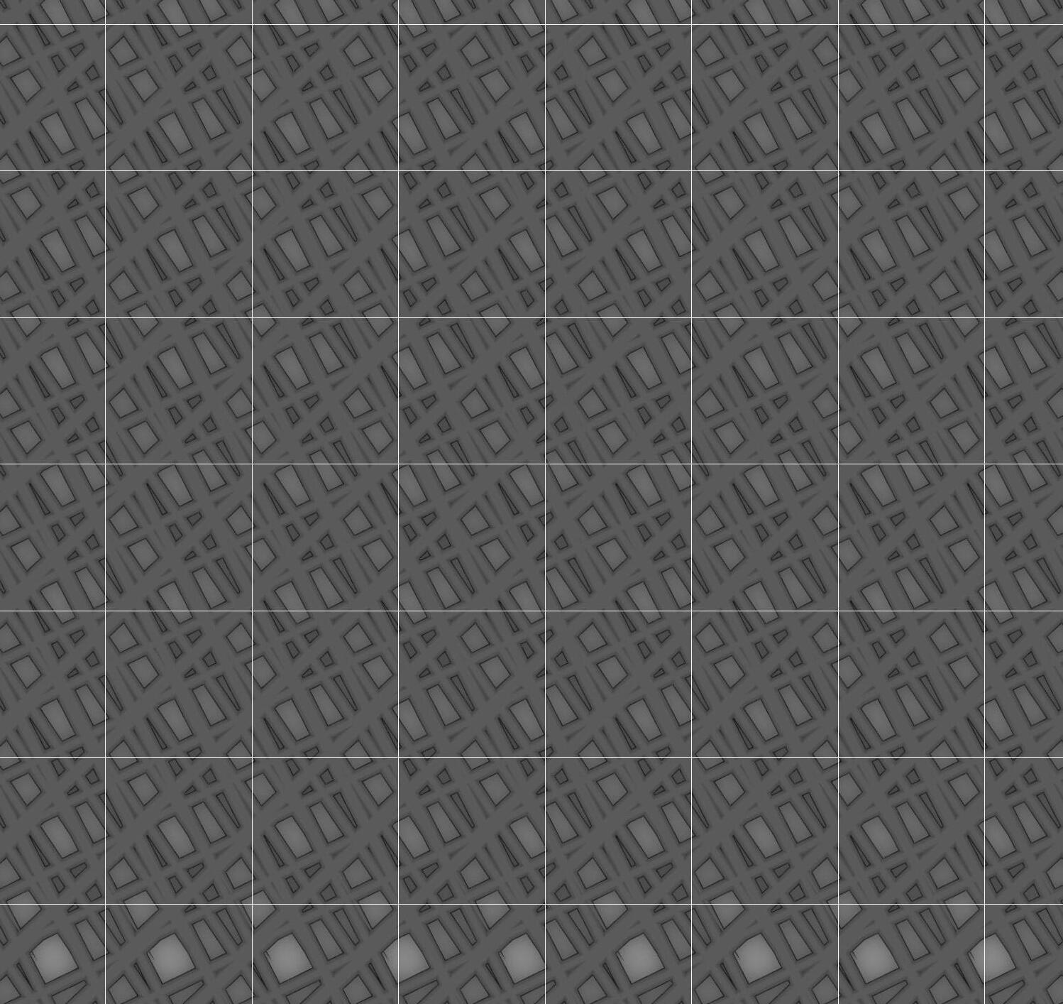
This pattern is to take inspiration from the honeycomb like nature of the morel cap with varying densities in shape, with more emphasis on smaller densities.


PATTERN 3 | ITERATION 3
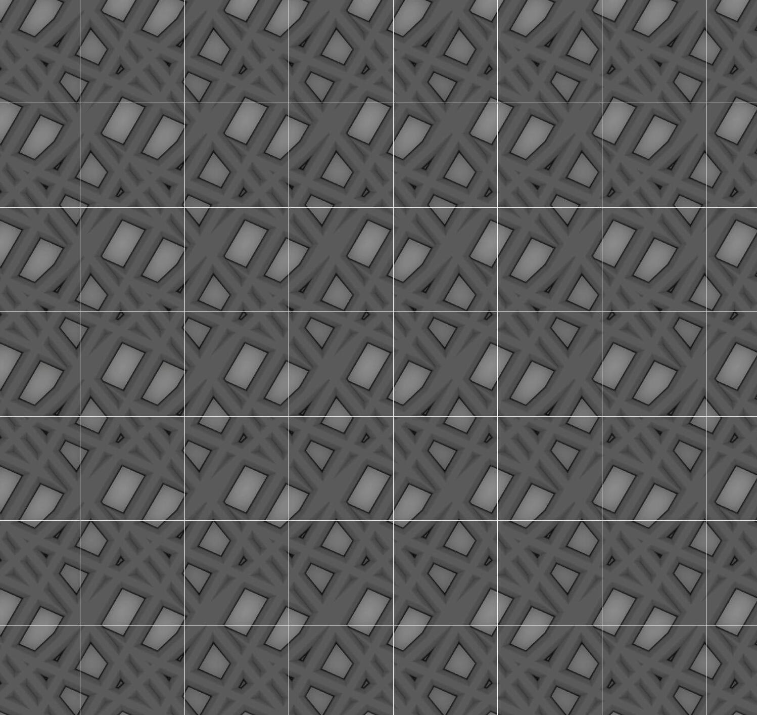
This pattern is to take inspiration from the honeycomb like nature of the morel cap with varying densities in shape, with emphasis on larger densities.


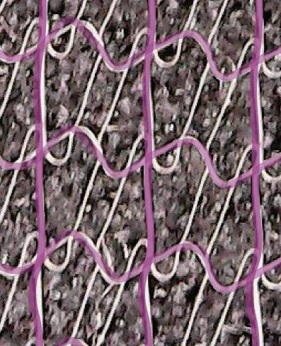
Initially with pattern development, the pattern that was first created with inspiration from the Bear’s Head Tooth Mushroom primarily focused on verticality of lines and developing a connecting strand to imitate that sense of travel. However, after printing, my direction in the style of the pattern shifted in emphasizing vertical overlapping density like the actual mushroom itself.
With further pushing of the design, considering each strand of the mushroom as a single line that is repeated over another much like the mushroom which grows over itself unlike the original pattern.
Body Copy


INITIAL BEAR’S TOOTH PATTERN ANNOTATION


DEVELOPMENT
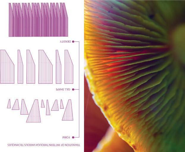
Initially with the first chanterelle pattern, the success of reflecting the shape of the actual mushroom itself was rather limited, with only a connection to the verticality of growth being created in the inital pattern. In further pattern development, the chanterelle was deconstructed in various forms for each iteration, with an emphasis on either density, form, and gill shape through each iteration.
In terms of progressive development of the inspirative pattern, the pattern became more representative of the chanterelle, but may pose risks to the growth of potential seeds and plants due to its density.
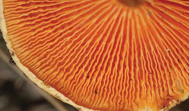
INITIAL CHANTERELLE PATTERN ANNOTATION



The primary goal of reproducing the Morel pattern was to lean on the organic and asymmetrical ridging/holes of the morel that is not commonly seen in other mushroom types. The importance of doing this was to not only create a more organic shape, but allow for more raw and organic growth of potential types of plants without putting a general sense of order for growth. Although the initial pattern is successful in producing a shape that is rounded after printing, it is less successful in producing an almost randomness to the individual unit.
With continued exploration, the next iteration of the Morel pattern is to create less of a standard unit to reflect the nature of the fungus’s ridges and holes across its surface. The newest iteration is meant to put more emphasis on the voids between each ridge rather than actual lines to allow for growth.


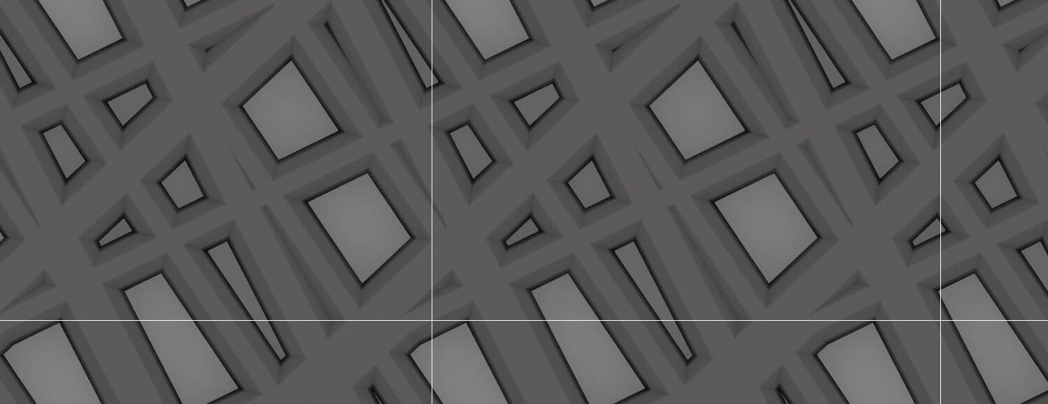


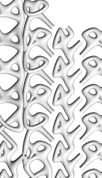
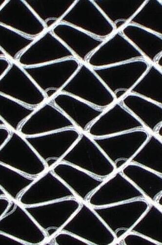
In producing the final pattern, the primary goal in comparison to initial iterations of the scaffolds was to produce a pattern that appeared more organic and flowing similar to the precedents in nature. With the finalized pattern, the inspiration with the gorge morel took precedent, with the irregularity of the canyons and valleys in the shape of the fungus carrying a desired aesthetic quality in the finalized pattern.
With the shape of the script utilized, minimal repetition of one object was ignored. Rather a repetition of multiple variations of shape and size was given priority over a recurred repitition of one object.

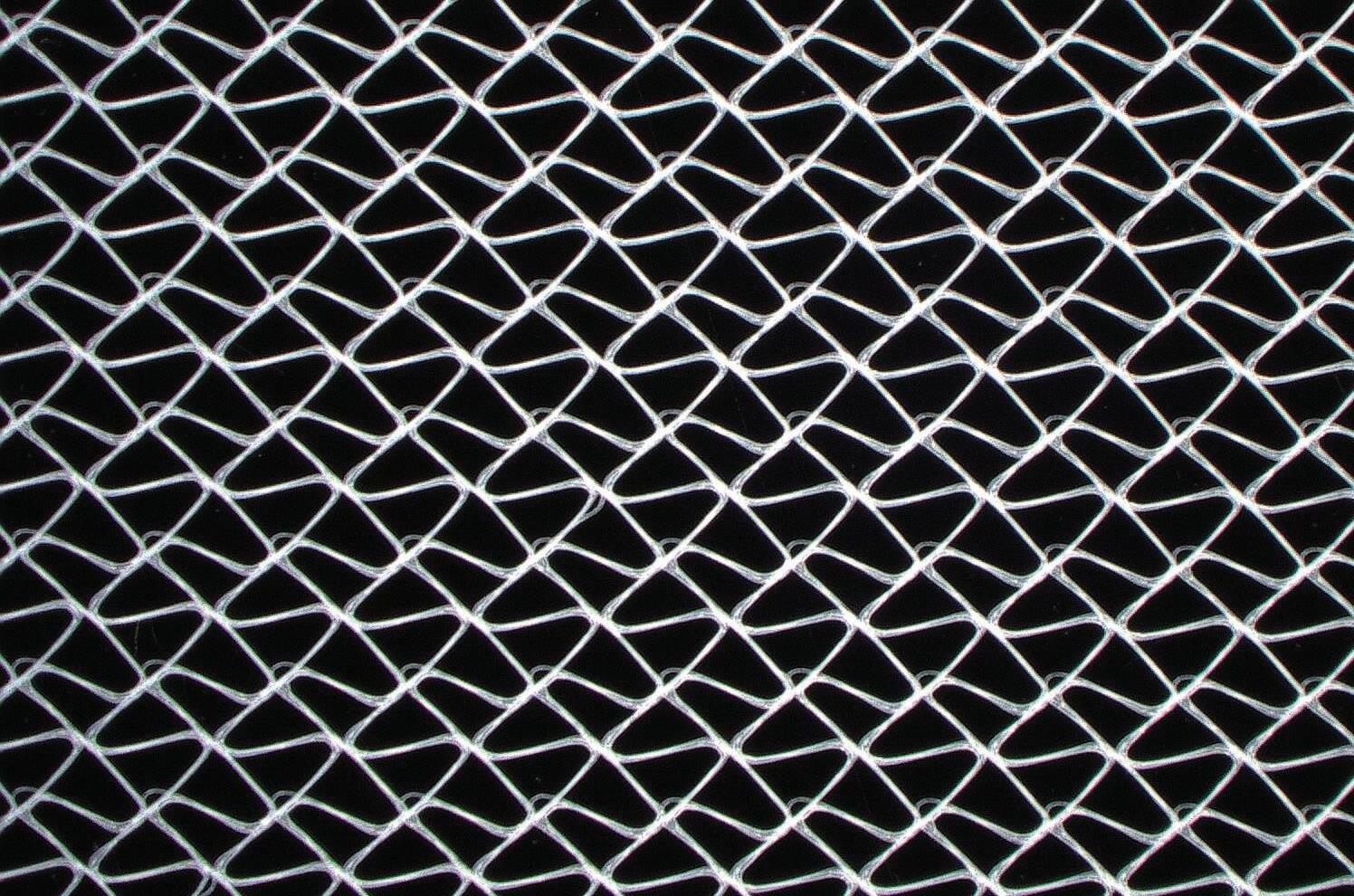
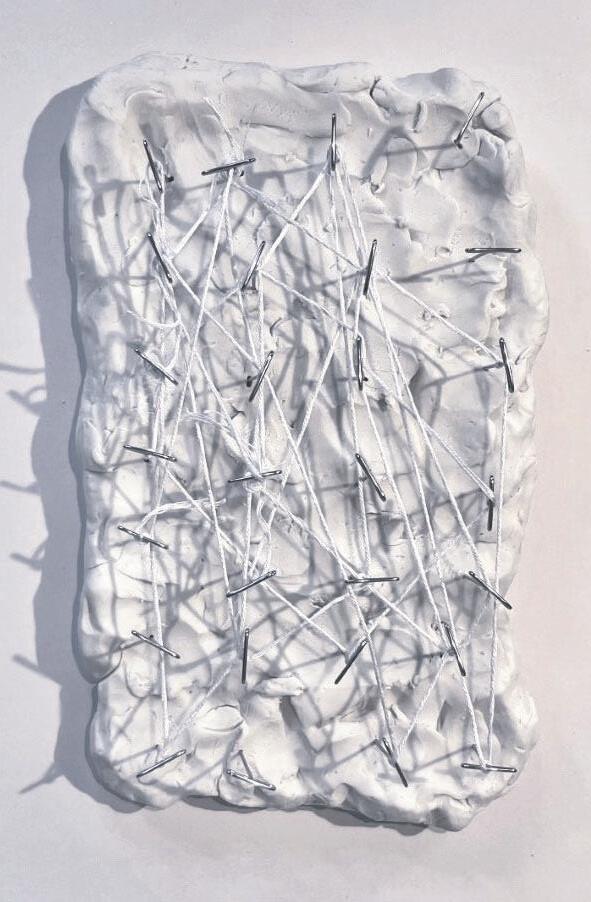


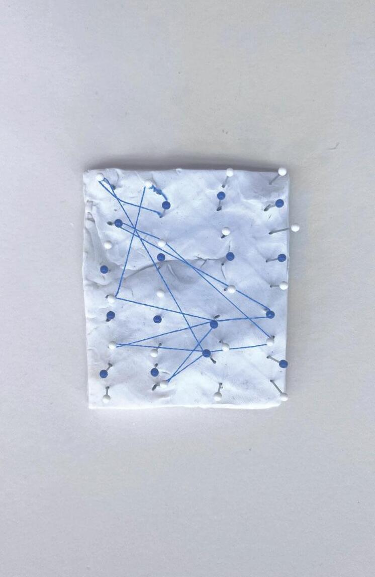
With testing the potential components, instead of producing a variance of patterns, threading shapes was determined using coordinated movements across each pin. Keeping a repetitive motion of specific distances across the entirety of the pins until each pin was threaded through. This action was to produce a pattern that felt more organic.
What’s noticed with the produced organic components is that they all carry a dense and overthreaded area while the outskirts are less dense. Going forward with future component iterations, an emphasis on a larger branch hierarchies adjacent to smaller branch hierarchies,


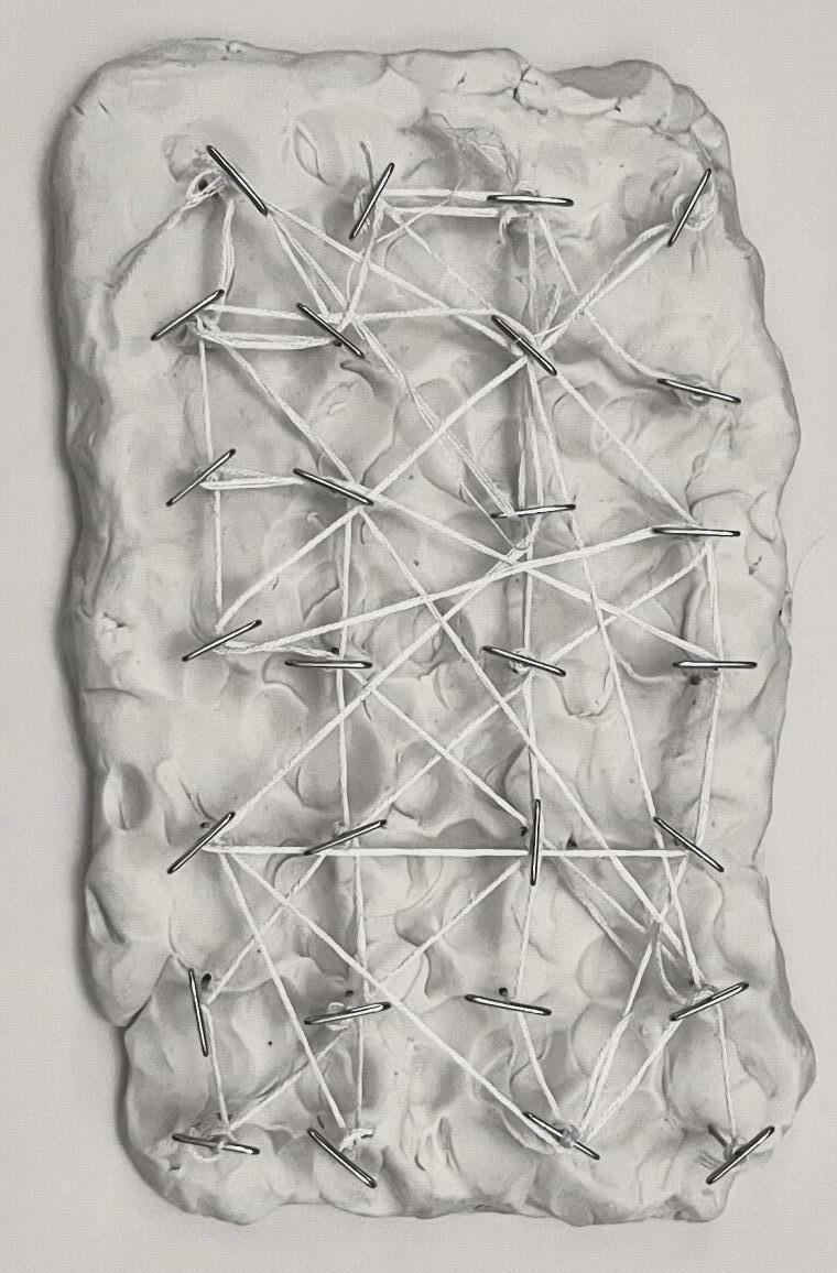
Moving forward with further testing, instead I shifted aesthetic and design directions towards creating specific branch modules using the same technique utilized in creating components. Using specific distances to move the thread throughout the pins, there was an emphasis on reaching the end of the module through this technique.



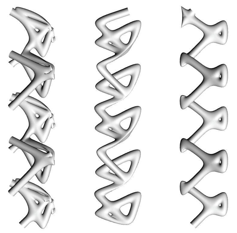
Through digital fabrication, the systemic pattern of movement utilized in the branch modules was further utilized to great the branch system. The primary goal was to offer as many connections between separate modules to produce more lines that plants could grow through without inhibitation.
The movement of the branches themselves are meant to imitate the canyons and curves present in the morel mushroom, with the connections creating a system of voids and lines that are similar to the mushroom.
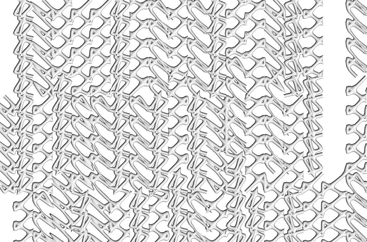
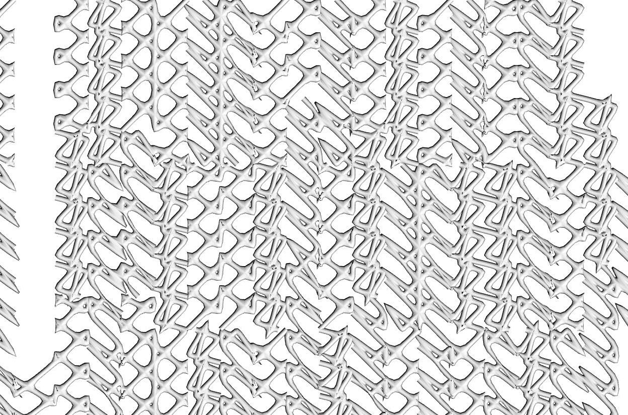
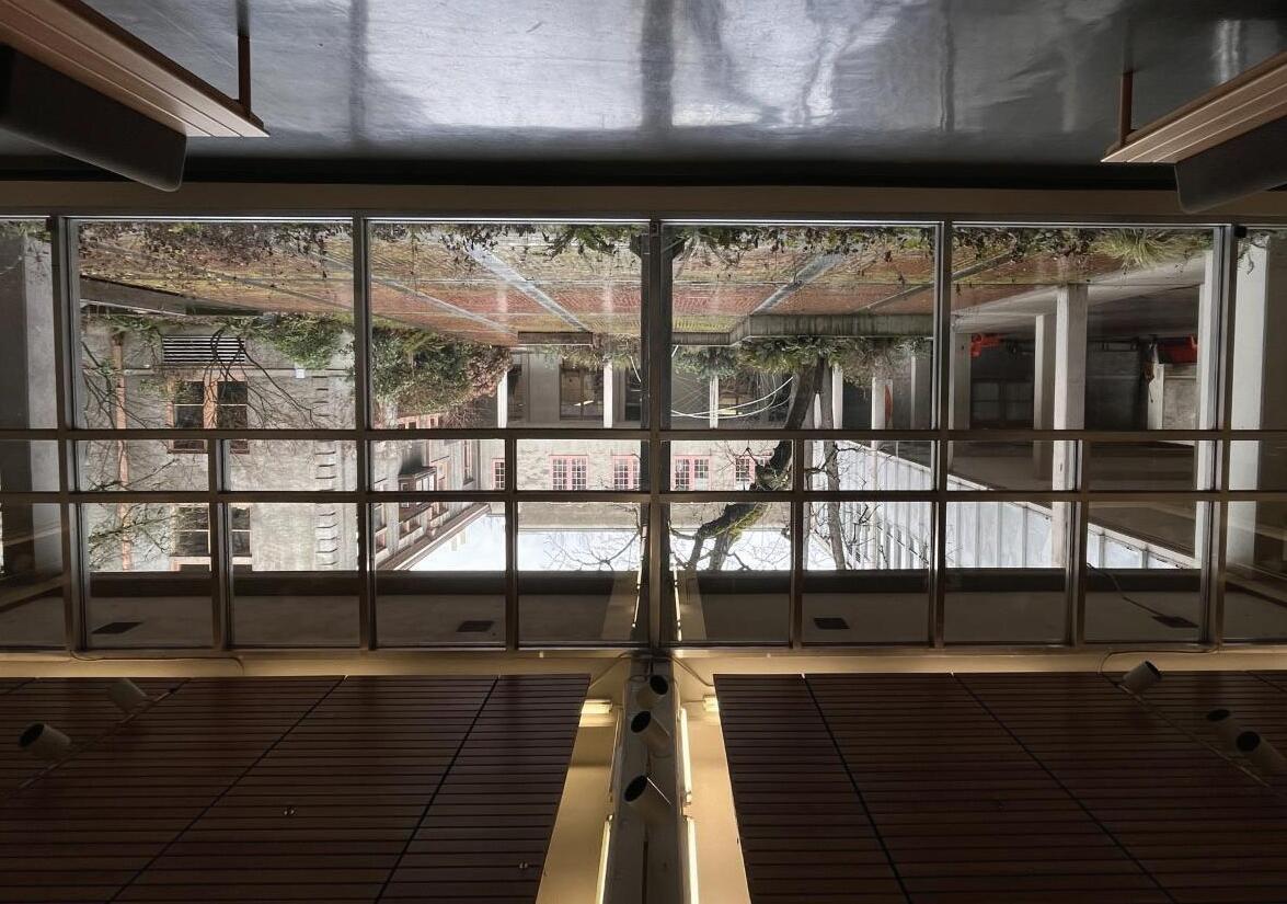
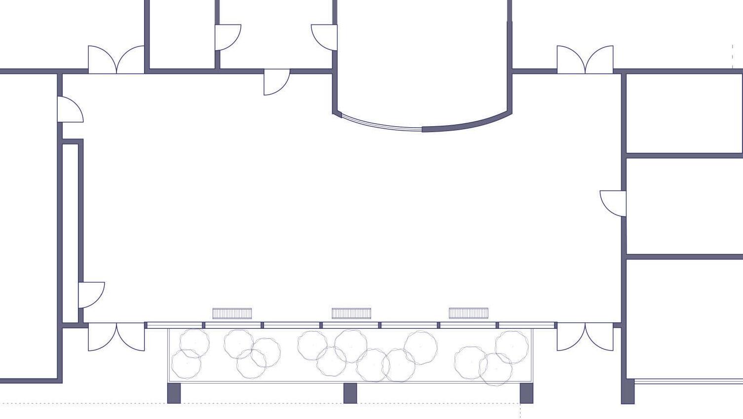
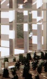
Moving into a spatial context, the Hayden Gallery on the first floor of Lawrence Hall offers a large amount of potential for both infrastructure connections and aesthetic additions. As a result of the connection to the courtyard, the design goal of this product is to bring nature inside and the man-made outside, creating a continues system in terms of infrastructure and space to bring attention to the underutilized gallery and courtyard.
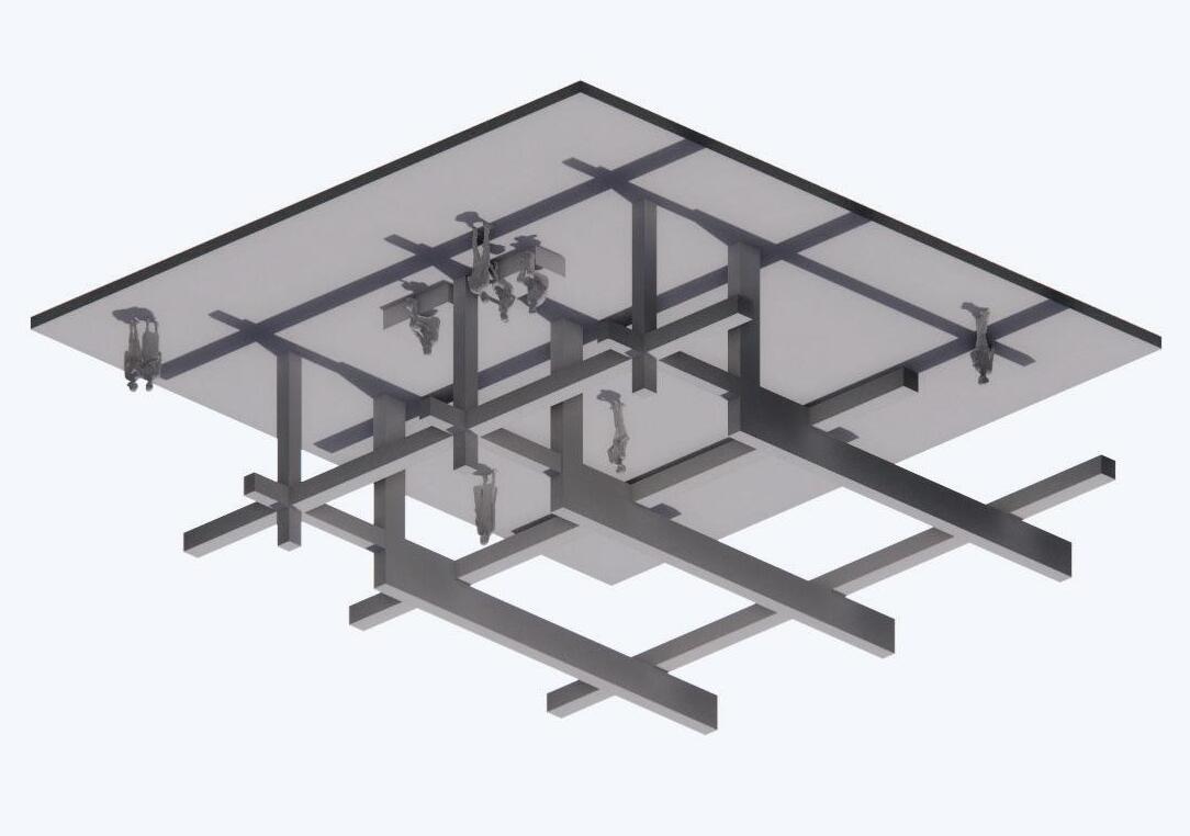
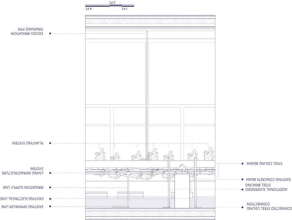
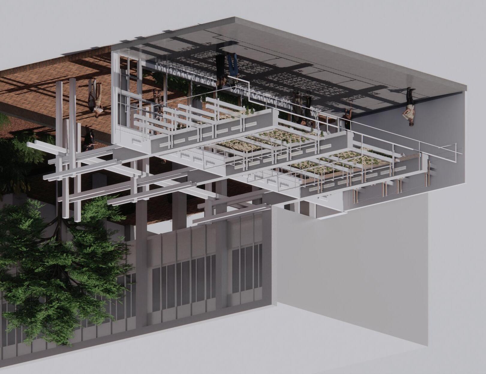
Utilizing the branch iterations and the potential systems created, replacing the ceiling paneling with the created system is a primary goal within this proposal. Creating a living paneling system that can connect to the existing infrastructure within the space & generating a more complete sense of space within a rather disjointed building.




WOODEN CEILING PANELS
GALLERY PERIMETER LIGHTING
SPRINKLER WATER SYSTEM
ELECTRICAL CONNECTION SYSTEM
VENTILATION SHAFT
GALLERY POD LIGHTING
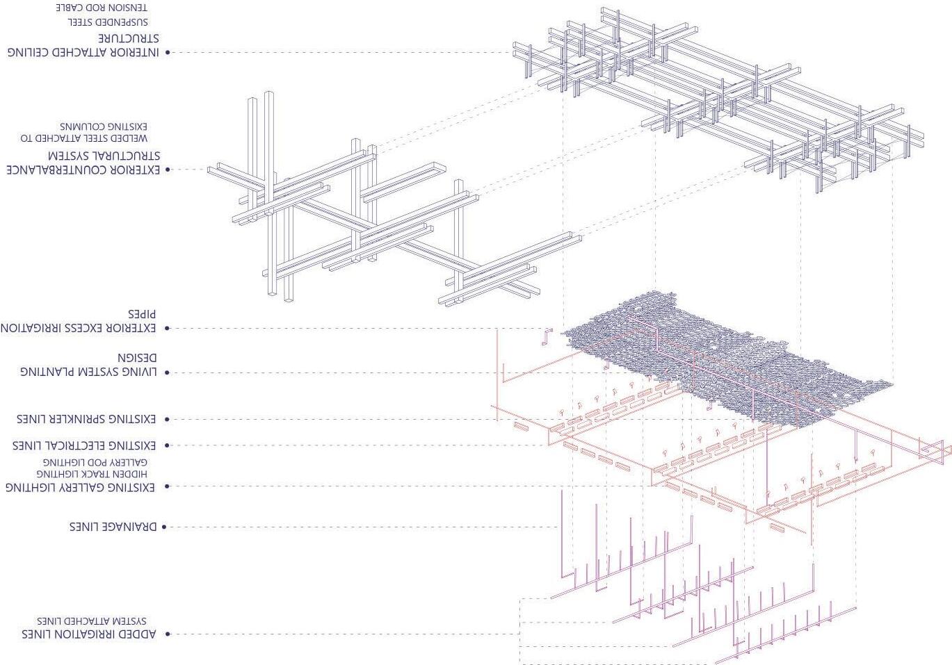
The infrastructure of the Hayden Gallery itself lends on to the existing structures put into place through Lawrence Hall. Primarily, the main infrastructure within the space are sprinkler lines and electrical lines that power the gallery lighting, with an emphasis on the importance of electrity. A mix of visually available pod lighting and hidden ceiling lights provide readily available artificial lighting to fill lacking light levels due to a north facing




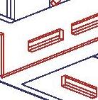
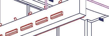

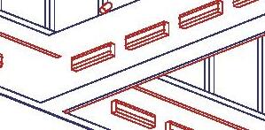

glazing system. Especially with the abundance of electrical lines within the gallery, this may pose potential in connections needed through horticultural lighting or may even present enough electricity for this function. However, this may present a potential overload in available resources and will most likely need infrastructure reconfiguration.
Additionally, the actual structure of the space itself, which lends to concrete beams in the gallery itself, supported by three exterior columns five feet from the glazing. Potentially, the structure itself may present a viable system for establishing a ceiling insertion. Very much so, the intent of much of the design moves that need to be made within the gallery are relying on the existing infrastructure and guinding lines established in the gallery.
HAYDEN GALLERY INFRASTRUCTURE AXONEMETRIC
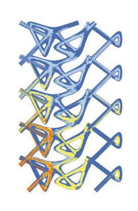
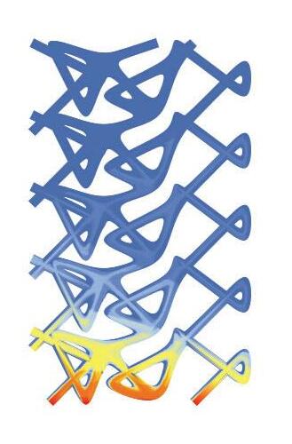




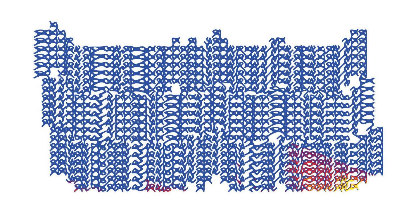
LUX LEVEL MAP IN RELATION TO LIGHT REQUIREMENT OF PLANTS
MEASURED 2.8.2023 AT 1:30 PM DURING AN OVERCAST DAY



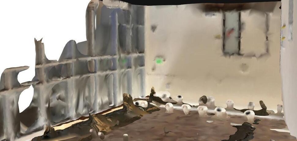
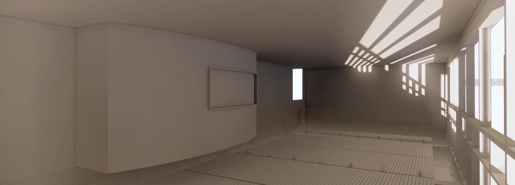
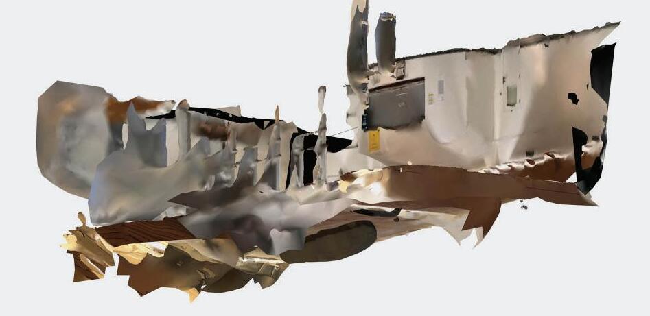
In comparison to the simulated light levels discovered utilizing Grasshopper in comparison to light levels measured in the space itself, it can be safely assumed that modules closer to the glazing itself (albeit sourced from northern light) will be receiving the highest amount of natural light in context of the entirety of the system. This may present the opportunity to utilize plants that require medium
amounts of sunlight without the addition of additional horticultural lighting. However for a large majority of the potential systems being added, low-light plants in addition to horticultural lighting will need to be utilized to access the potential of these living systems. The plants that show the most potential, both in being able to live in the space as well as contributing to the quality of the space
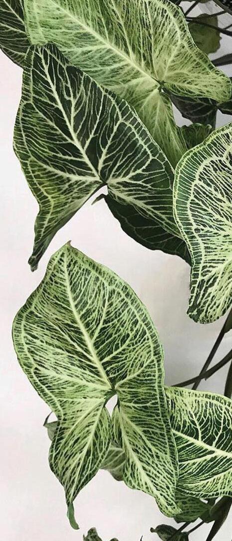
are most likely hanging plants that can create a sense of dimension. Low-light plants that may be able to grow and function within the installment and within the space/infrastructure itself may be the pothos hanging plant, the philodendron, and the syngonium. These three plants may be dispersed within the addition, but all three are capable of living in light levels below 807 lux (majority of the space falls
under these light levels). In terms of a plant that can survive in levels above 807 lux, the silver leaf monstera displays potential in being utilzed within the system in the areas directly connected to the glazing.
Primarily, the first step in moving the design forward is designing the future additions to infrastructure to support the connection of the system to the actual space itself. Additionally, establishing successful drainage system that is functional and does not detract from the spatial quality of the gallery. Furthermore, the potential of creating a recirculating water system that could operate on a water cycle that not only receives water from the interior, but potentially from runoff from exterior sources.
With the spatial goal of this project focusing on creating an interconnected continuity between the gallery and the courtyard, as well as increasing interest in using the courtyard, the addition of spatial infrastructure is needed. Potentially, this is through creating exposed supporting structure that connects to existing structure and additionally is created if needed. This addition will serve a double purpose; to create a structural system that could support the ceiling system of the project and create spatial guides and subtlety.


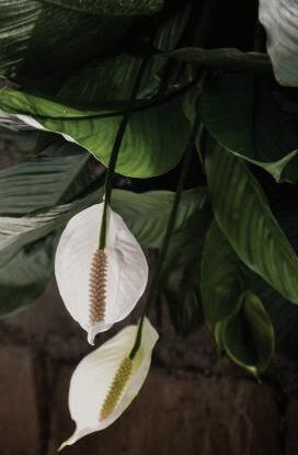
Peace Lily (ppfd): 20-40 (umol/m2/s)
ppdf conversion to lux levels:
870-1739 lux
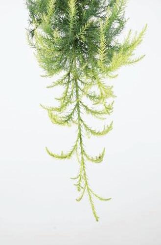
Sekkan Sugi (ppfd): 69-94 (umol/m2/s)
ppdf conversion to lux levels:
3015-4122 lux
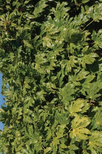
Japanese Arelia (ppfd): 11-21 (umol/m2/s)
ppdf conversion to lux levels:
478-913 lux
In the context of the Hayden Gallery, when measurements were taken during the winter of 2023, the space itself promotes indirect northern light that ranges between 200-1300 lux within the space. Accounting for this, the light levels within the space during this time period is generally successful as the selected plants fall within the average lux range. However, due to the intensive light levels needed for the sekkan sugi and for the peace lily to fall within the highest range, additional horticultural lighting is needed.
Within the Hayden Gallery, there are supplemental lighting available to provide low-lighting within the space. Assuming, at the lowest range, that the flourescent tubes that light the room provide 1100 lux at a distance of 2 ft, the lighting is enough to supplement the peace lily and arelia plants that need excess light. However in the areas with the sekkan sugi planted, the strength of the existing lighting are intensified an additional 1000 lux.
INITIAL LIVING INFRASTRUCTURE MODULES
The original pattern of the living system mainly focused on excessive overlap and intersection to draw upon the original morel inspiration. It appeared successful in terms of shape and aesthetic quality. However, the pattern lacked the success of incorporating into existing infrastructures. The final proposal is meant to slope downwards to account for irrigation runoff. Additionally, points of mass intersection are lifted upwards to connect to irrigation lines.
Each individual module is meant to have three gaps between the piping in variable forms to imitate the canyons and ridges of the morel. Additionally, each branch module will be expanded in scale by a factor of two to create a sense of gradient between the connecting modules.

FINAL LIVING INFRASTRUCTURE MODULES
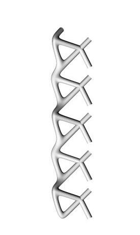


FINAL LIVING INFRASTRUCTURE


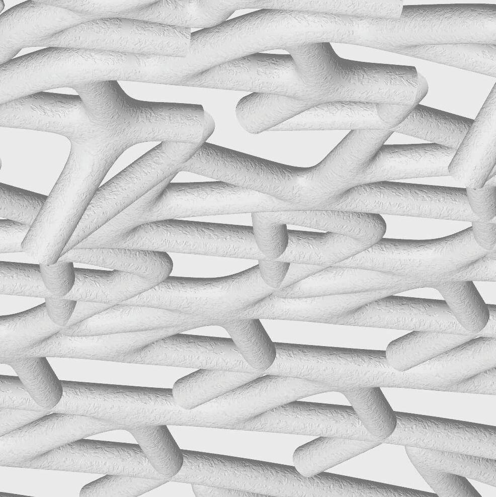


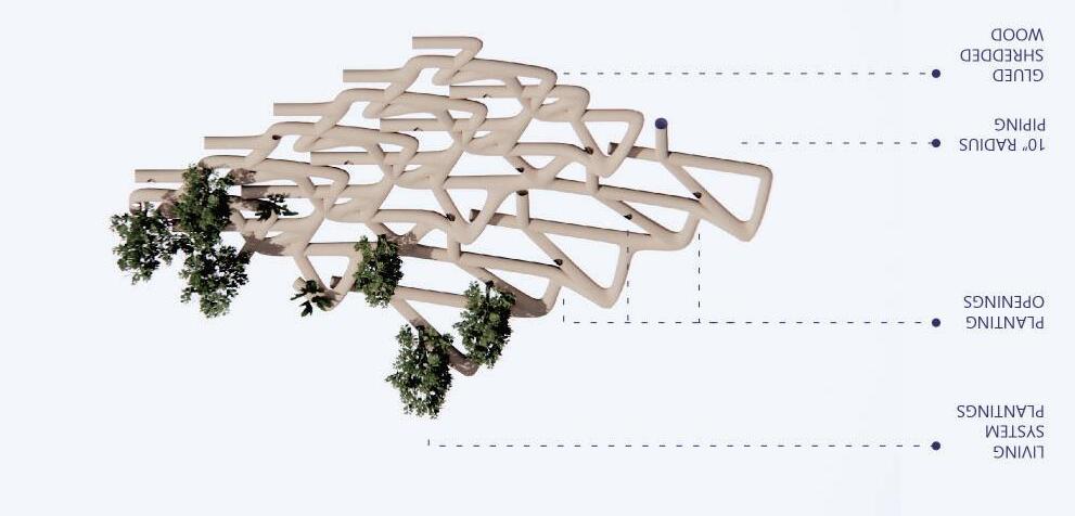
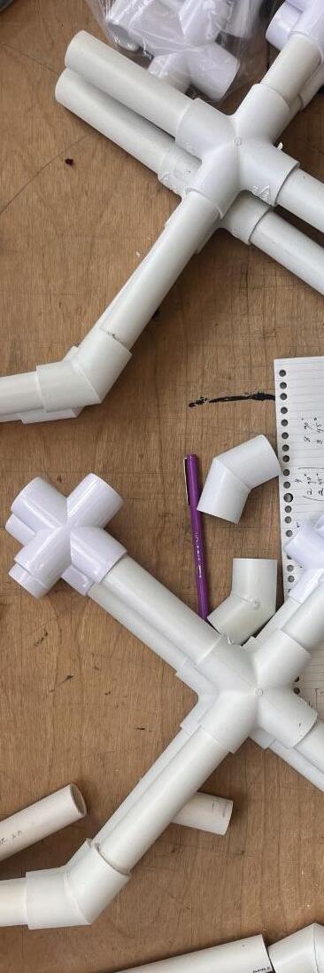


In constructing the 1:1 model, choosing a branch module that could allow for simplified connections between multiple pipe lines was a necessity to allow for easier construction. Doing this allowed for a simple model to construct and could be retrofitted for reconstruction.
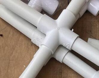
The pipes themselves are retrofitted at 3/4” and feature connector fittings using 45O, 90O and cross connections. A fourth type of connection was needed using piping similar to a hose in material and bending capabilities. However, due to the rigidity of the PVC pipe connections, the 1:1 module was less similar to the expected result. The finalized result became more of an idea of the selected module. Further iterations in connections for a refined version of the 1:1 module will be needed to reach a finalized model.
Using PVC piping to construct the 1:1 model, requiring various different connection fittings and tubing. The PVC was then cut into pipings sized at dimensions of 0.186’, 0.236’, 0.373’, 0.471’, 0.559’, 0.707’, and 0.75’.
Additionally, to create the entire module, 12 cross connections, 8 90O elbows, and 8 45O elbows are needed to assemble, as well as using portioned off bendable pipes to retrofit connections when needed.
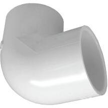

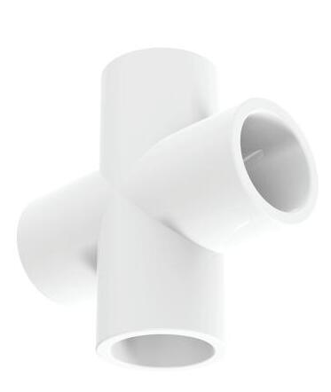
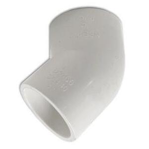


1:1 MODEL
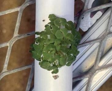
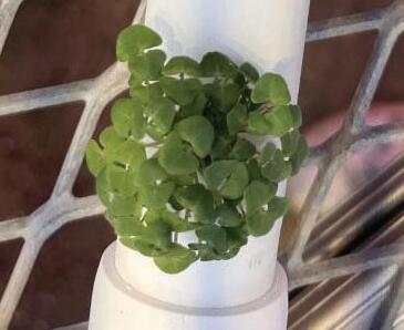
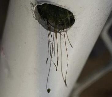
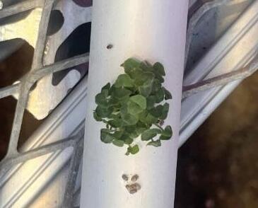
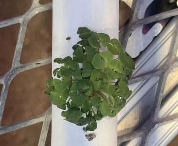
For the plantings in the 1:1 model, a mixture of chia and moss were used to fill the planting spaces, while dirt and fertilzer were placed into the pipes to allow for free growth.
The initial observation of the chia and moss growth displayed that intense heat and electrical lighting dried out the dirt into a crust. This crust had to be removed to allow for further growth of the chia. The second and third observations of the chia and moss growth showed successful growth as a result of condtions being changed to sustain healthy development of the plants in the 1:1 model.


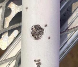




INITIAL GROWTH OBSERVATION
SECOND GROWTH OBSERVATION
THIRD GROWTH OBSERVATION
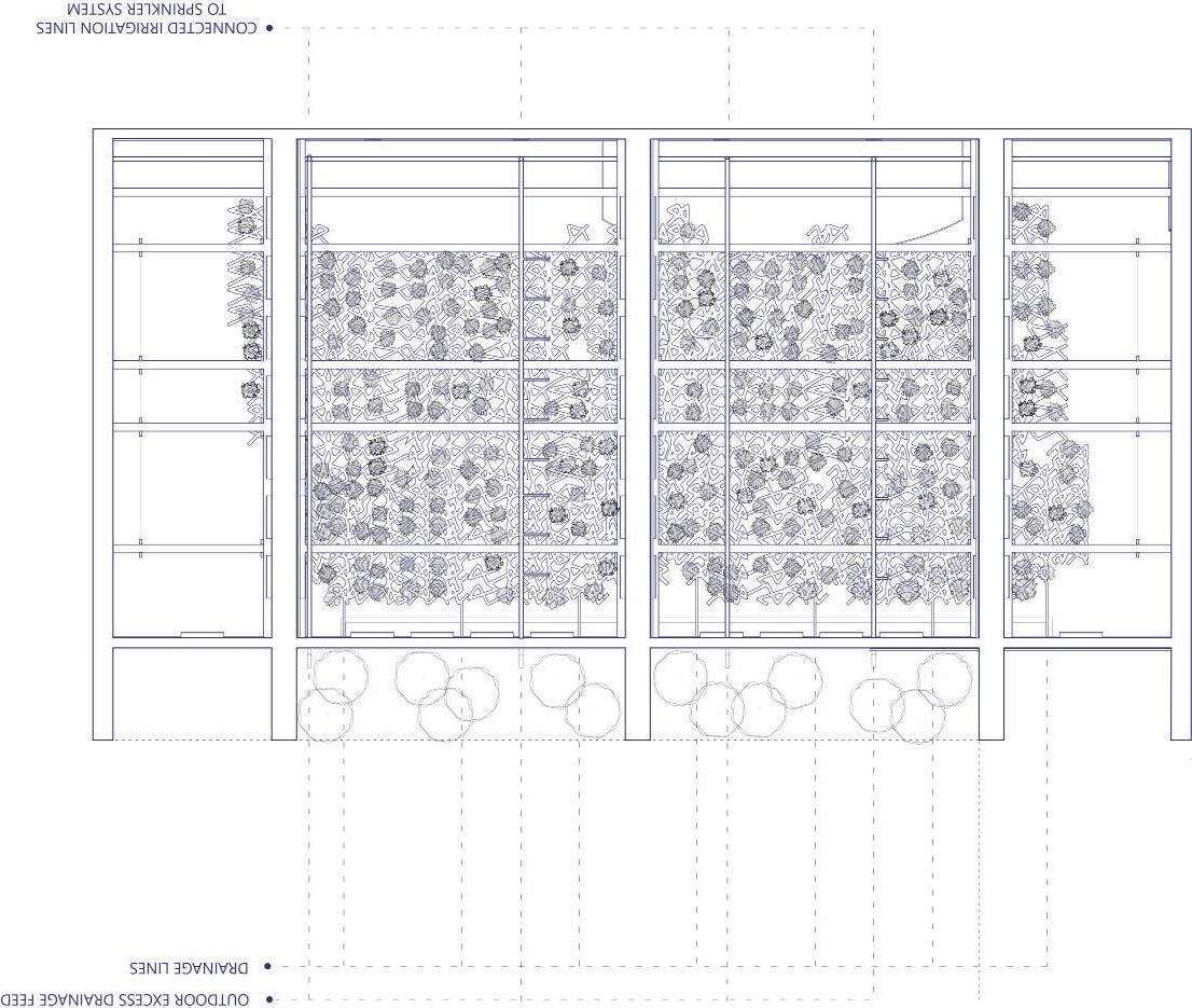
In further design research in deciding planting types for the living system, using a combination of information gained from natural lighting systems as well as choosing plants that draw inspiration from the plants in the adjacent courtyard. This lead to further research into plants that could survive in low-light and colder environments as a result of the low levels of indirect lighting, and especially into plants used in Japanese gardens.
To account for plants that could survive in low-lighting and the conditions similar to the plants in the courtyard, my research brought me towards using the Peace Lily (Spathiphyllium) and Japanese Aralia (Fatsia Japonica). Additionally, the areas near the glazing receive high levels of lighting, and with keeping with the precedents, the Sekkan Sugi (Cryptomeria Japonica) was selected due to it traditionally being an outdoor pine but can be utilized in indoor applications. The wider dimensions of the piping allow more room for the roots of these plants to grow. This remains especially important in the case of the sekkan sugi, as the pine utilizes a taproot growing structure.


HORTICULTURAL PLAN (FROM ABOVE)

COMBINED SYSTEM AXONEMETRIC DIAGRAM



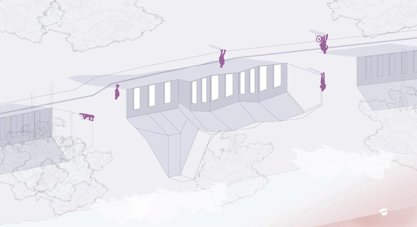
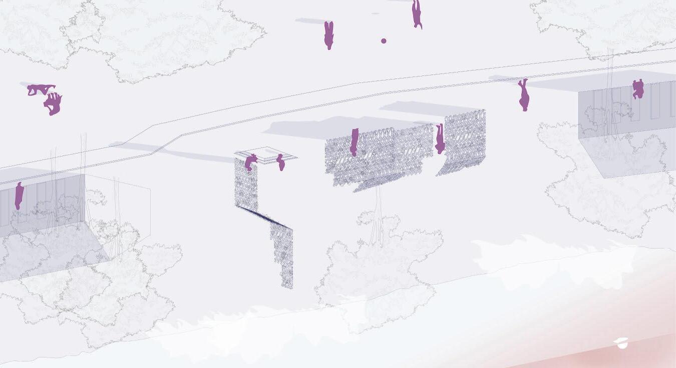
Looking further into future explorations of living infrastructure, this proposal focuses on the possibilities of these systems either being incorporated or even replacing commin architectural pieces. Taking inspiration from the possibility of mycelium based masonwork, with further study of living systems involving a similar exploration of plants and roots becoming architectural explorations.
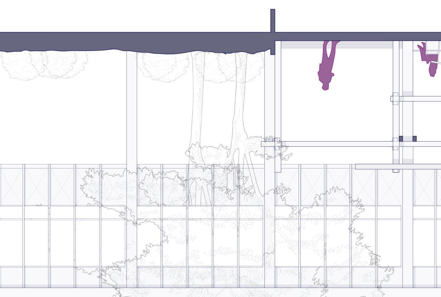
In this study, it focuses on the possibilities of the residence and primarily within the single-family residence in a neighborhood context. In various ways, the living infrastructure would feed into the possibilities of structure, facade, and eventually wall and residence systems. Within a structural application, a piping framework would act as a casing to allow plant or tree roots to grow and form stiff
structure. In a facade application, the living system would imitate the idea of ivy, doubling as a thermal barrier to sunlight as well as contributing to the design capabilities of the exterior residence. In a wall system application, living walls could act as dividing systems (stationary or non-stationary) and begin forming the actual spatial framework of the residence.


SYSTEM AS FACADE




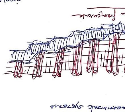

In beginning Pompidou II the prospect of an expansive system as a final proposal did not cross my mind. From the examples, I expected the design to follow the general guideline of a linear wall system. However, in taking the proposal towards its current direction, it allowed further exploration to go in a non-linear direction and take inspirations from precedents that I haven’t been able to in prior design studios. The freeform nature of the studio allowed for greater explorative designs and in creating a unique pattern. Additionally, the idea of creating architectural patterns with living systems with the essence of biomimicry in mind allowed the system to breath to its fullest potential. Keeping the idea of Pompidou in mind, the contrast of architectural systems with living systems creates the greatest potential for success in the design.
Potentially, further exploration of the living system pattern could lead into creating a self-sustaining system. While initially exploring this with an excess drainage system that moves into the outdoor vegetation, creating a system that could recycle both the outdoor and indoor water would lead to a further refinement of the design. Overall, the design remains successful through making minimal change to the existing infrastructures as well as reflecting the beauty of the initial precedents in the final design.