
POMPIDOU II
ARCHITECTURAL LIVING SYSTEMS
LINDSAY AHMED


ARCHITECTURAL LIVING SYSTEMS
LINDSAY AHMED

INTRO
Hi! my name is Lindsay Ahmed and I am a 3rd year architecture student from Boston Massachusetts. I am intrested in reasearch based architecture and am exicted to create sustainable and green living systems and learning about the process.
ARCHITECTURE YEAR
3rd Year
For this project we are beginning to study the capabilities of living systems within architecture and landscape architecture. The objective of this studio was to look at existing systems within buildings and how one could possibly tap into these systems and create a functional space for a living wall. Although the majority of this studio was hypothetical it allowed for us to observe and predict how to create a sustainable and working system. For my specific system I picked creating a PVC pipe living system on the columns of the design library. The inspiration for the studio was Pompidou II so I took into the account of creating a beautiful piece off of a place that is surrounded and can foster a community. Throughout this studio I have taken away a lot of knowledge of the
complexity of why it is so hard to sustain green walls. Even thoughout this is new research it will be really interesting to see if MEW scaffolding pattern can host plant life and help make a greenwall living system able to be long lasting.


SCAFFOLDS
1. MEW SCAFFOLD PATTERN
STUDIES
2.LIDAR
3. DIGITAL TWIN
4.TECHNICAL ELEVATIONS AND PLANS
5. PLANS OF LAWERENCE
6. BUILDING SYSTEM AXONS
8. LUX MEASUREMENTS
9. LUX COMPARISON
10. SCAFFOLD STUDIES
11. WATER FLOW ANALYSIS
12. PROPOSED/SELECTED PATTERN
13. PLANTING PALETTE ELEVATIONS AND DIAGRAMS
14. CALCULATION OF SPECIES
LIGHT NEEDS
7 ENVIRONMENTAL ANALYSIS
PROTOTYPES
1. PROCESS WORKWW
2. JOINT CONSTRUCTION DIAGRAMS
3. COMPARISON OF ORIGIONAL VS FABRICATION
4. TECHNICAL DRAWINGS
5. SERIES BUILD PHOTS
FINAL DESIGNS
1. SERIES OF COMPARISON AXONS
2. BUILDING SYSTEMS
3. FINAL RENDERED VIEWS
4. VR IMAGING
5. MATERIALITY
6. SIZING
7. OPENINGS

4
PHYSICAL MODELS
1. PHYSCIAL MODELS
5
CONCLUSIONS
1. CONCLUSIONS
MUSHROOM INSPIRED
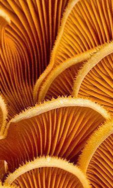
In this pattern of study the idea was to play with small vertical lines to get the same type of verticallity on oyster mushrooms. It was important to play which sizing of positive and negative space and showing how vertical lines can be beautiful
The speed printed would be F200


GRAPEFRUIT INSPIRED
In this pattern of study the idea was to play with vertical as well as horizontal intersecting lines. The goal was to make sure that the lines do not overlap too much and try to create the patterns of grapefruit veins.
The speed printed would be F200


HONEYCOMB INSPIRED
In this pattern of study the idea was to recreate the hexagon like textures in a honeycomb with overlapping elements.
The speed printed would be F200


LEAF CELL INSPIRED
This pattern goal was to mimic the detailed cells in leaves.
The speed printed would be F200


BUTTERFLY CELL INSPIRED
For this pattern I wanted to mimic the way that the little scales in wings tend to group together and migrate to a part of the wing, whether that be because they are certain colors of shapes.
The speed printed would be F200


PINECONE INSPIRED
In this pattern I wanted to mimic the simplistic way that the parts of a pincone naturally overlap and go together to protect the seeds.
The speed printed would be F200


REFLECTION INSPIRED
In this abstract pattern I really wanted to mimic the chaotic way that water/liquid can reflect off of different kinds of surfaces.
The speed for this print was f20.


TREE ROOT INSPIRED
In this pattern the goal was the create a wavy overlap of lines like how routes of a tree overlap themselfs or how they intertwine with other trees.
The speed for this print was f300.


BARK INSPIRED
Much like the reflection pattern and similarily to the root one, I wanted to showcase how chaotic the patterns of bark on trees can be. As chaotic as it can be it can also be quite beautiful.
The speed for this print was f200.


This pattern was similarly inspired like the mushroom pattern. I was inspired by looking at intersecting lines at a horizonal level and creating thicker lines and thicker pockets.
The speed for this print was f200.


BUTTERFLY
When analyzing the way that the butterfly print came out, one can see that there is a lot of overlapping, creating little pockets in the scaffold. This was more than I initially intended for my design but it turned out close to what I imagined it to look like.

SYMMETRICAL OPEN SPACES, LESS SMALL SPACES MORE LARGE OPEN SPACES
IMAGE: 3D RENDER VS. 3D PRINT

MUSHROOM
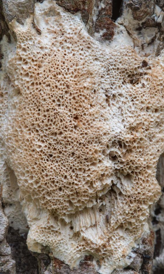
When analyzing this pattern there is s lot of overlap, like the previous pattern. The overlaping layers seem to not be extremely clean and more messy and drop like.

ANGLED OVERLAPPING SEEMS
IMAGE: 3D RENDER VS. 3D PRINT
LAYERED ON TOP OF ITSELF

FUNGUS
For this technical and final print one can observice that its a combination between the preious printed patters. It has interwooven with itelf and could be extremely sucessful when hosting plant lives.

TRIANGULAR POCKETS CHANGED TO CIRCULAR

When deciding what to print for the final pattern, it was important to observe and test to see if the scaffold could host multiple different forms of plant life. For my design I decided to go with the concept that was inspiried by butterfly wings, because as you can see there are a lot of intersecting lines as well as positive and negative spaces.


IMAGE: FINAL SCAFFOLD PRINT

LAWERENCE DESIGN LIBRARY
For this imagery we were tasked to origionally use a photogrammetry progran that unfotunetly did not work for my space because of all the windows in glare. I then moved onto use a scanning program lidar on my phone to capture the image seen next to the text. As one can see there are still spots where the program did not pick up things clearly, but over all the imaging is great.

OPEN SPACES WHERE IMAGE WAS NOT PROCESSED

IMAGE: LIDAR SCAN OF SPACE
LAWERENCE DESIGN LIBRARY
Because the lidar imaging did not pick up everything that was necesary for understanding the space utilized for my project, I was tasked to create a digital twin. Here I used the program rhino to get a better understanding of the space, and allow for flawless mock ups and future renderings.


Here shows my plans for Lawerence design library. These were helped drawn by the mechanical and electrical plans of lawerence from the 90s. Here for the plans I switched over to revit to make them as clean and professional as possible.

IMAGE: PLAN OF DESIGN


LAWERENCE DESIGN LIBRARY
Here shows elevations for lawerence design library. On the left will be a technical elevation of the space itself. Next to it is an elevation that also highlights the different hookup/systems that will be tapped into in order to maintain and sustain the living system.


IMAGE: REGULAR AND TECHNICAL ELEVATIONS


LAWERENCE DESIGN LIBRARY
On this spread once can see the different axons to create a visual of the different types of systems that will live within the living system. During these diagramatic axons the different types of systems will be showcased throughout. For this particular spread the lighting and electrical are highlighted.












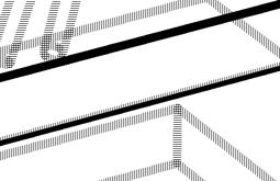

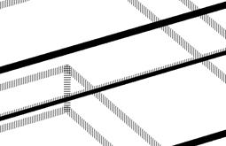


IMAGE:


LAWERENCE DESIGN LIBRARY
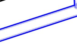
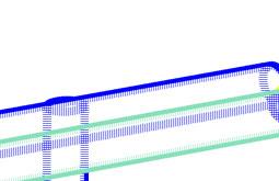
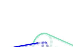
On this spread once can see the different axons to create a visual of the different types of systems that will live within the living system. During these diagramatic axons the different types of systems will be showcased throughout. For this particular spread the lighting and water and the whole system are highlighted












LAWERENCE DESIGN LIBRARY
Like the previous set of diagramatic axons, in this spread the different types of systems will be highlighted to showcase the systems and their connections to the library as a whole instead of just the living system. Here one can observe the electrical and hvac systems





















LAWERENCE DESIGN LIBRARY
Like the previous set of diagramatic axons, in this spread the different types of systems will be highlighted to showcase the systems and their connections to the library as a whole instead of just the living system. Here one can observe the lighting and water systems.





















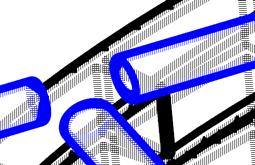





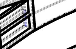





IMAGE:










LAWERENCE DESIGN LIBRARY
Like the previous set of diagramatic axons, in this spread the different types of systems will be highlighted to showcase the systems and their connections to the library as a whole instead of just the living system. Here one can observe how the whole system ties together in both axon format as well as a plan.


LIVING SYSTEM
In this imagery there are two environmental analysis of sunlight within the living system. Using an advanced grasshopper script we were given parametrics to change to show the true exposure of our living system. On the left is the system as a whole and on the right is the annual lux measurements throughout my liviving system captured midday in June as well as December.


LIVING SYSTEM
In this imagery there are two environmental analysis of sunlight within the living system. Using an advanced grasshopper script we were given parametrics to change to show the true exposure of our living system. On the left is the system taken from January 15 at noon-June 15 at noon and on the right is taken from July 15 at noon to December 15 at noon.
JANUARY-JUNE


JULY-DECEMER SOLAR ANALYSIS
NORTH FACING


LIVING SYSTEM
Since it was hard to see the stark differences between the months that emit the most light and the months that emit the least amount of light a third study was conducted. Here there is a study only taken on June 15 at noon which shows that most the southern and northern facing facades are faced with a high lux measurement, however it remains mostly warm and in the 1000 range. On the otherhand the Decemeber one is really interesting because in the north facing facade it has the highest amount of lux which is close to 3000 and in the south facing facade the lux is around 300.


BRIGHTEST

DECEMBER SOLAR ANALYSIS
NORTH FACING

IMAGE: ENVIRONMENTAL ANALYSIS
LIVING SYSTEM
Within this imagery one can view and analyze the lux measurements that were conducted using the sunlight measuring tool using a grasshopper script. On the left it shows the actual lux conducted at a diagramatic form and on the right it shows the predicted lux annually of the space if I were able to reach the top of the space on a latter.

HIGHEST LEVEL OF LUX PREDICTED


LOWEST LEVEL OF LUX PREDICTED
LIVING SYSTEM
With the images to the left they represent a 2D pattern study that was conducted mid quarter. These studies were to show how our systems could attatch to pipe, and we were tasked to expore that by using string and how it could live within our potential system. We also conducted block studies after in rhino to decide if a modular pattern or a linear pattern would be more sucessful in our space. For my particual design what I took from the first study was to have a combination of the additive and subtractive methods. Additionally, from the second study I used a linear pattern.


COMBINATION PATTERNING


LIVING SYSTEM
Here you can see the proposed pattern selected for my living system. The majority of the studio I was studying the pattern to the left. However, when I built to 1:1 model, conducted the light study and waterflow study, there were major flaws within the system. The next move forward was to simplify the design, which you can see on the right. This was a move I decided to make on week 8. This was extremely challenging but it was worth it because I created a more sucessful living system than the origional design.

IMAGE: PROPOSED AND SELECTED PATTERN


INITIAL WATER FLOW
Within these images you can see how water travels throughout my living system. There are still flaws within the waterflow and I will probably need to add in some additional support to ensure that the water can connect to each of the plants that live within my system.

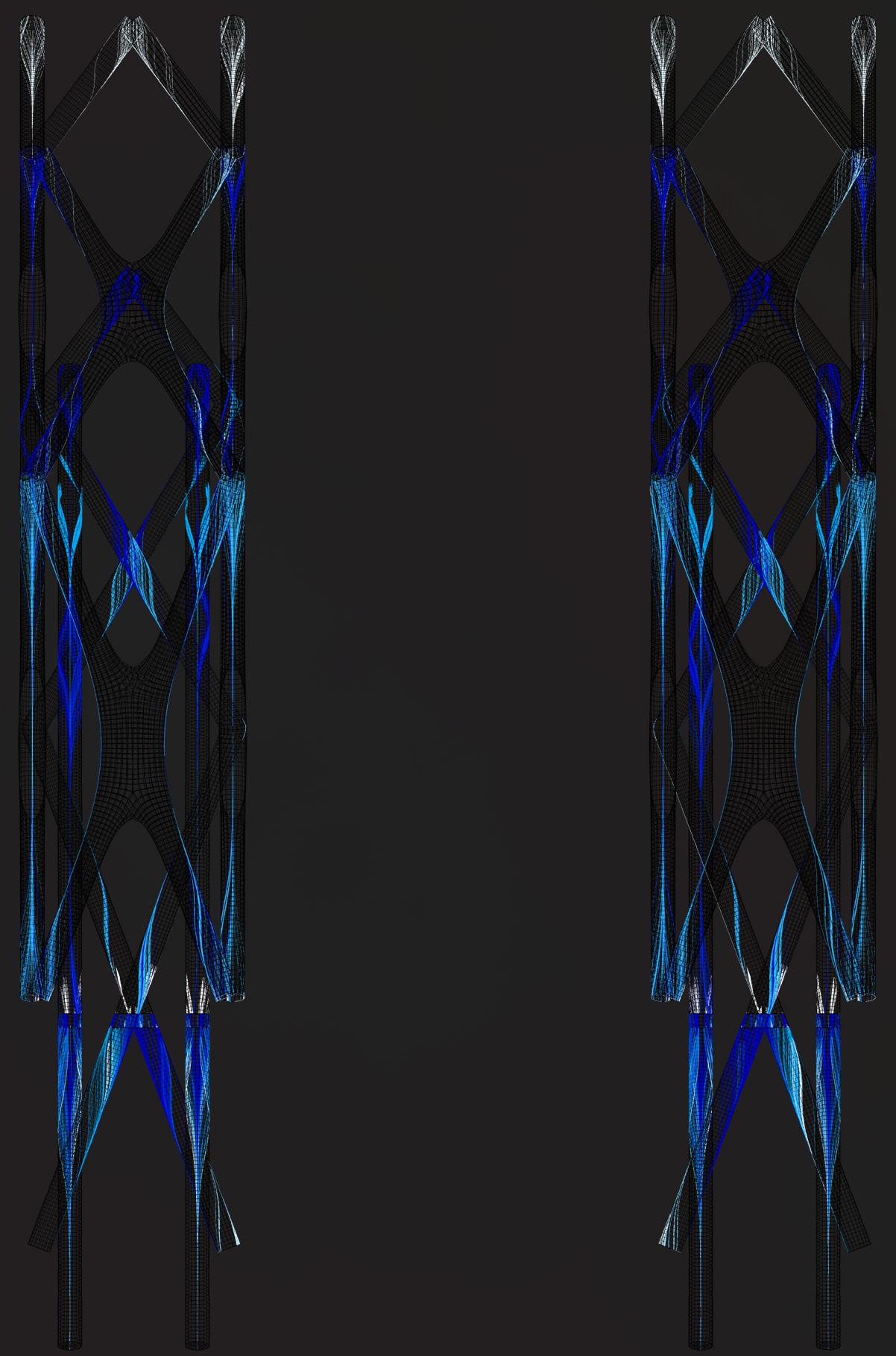
IMAGE: WATERFLOW ANALYSIS

INITIAL WATER FLOW
Within this spread I added in some additional support and created actual openings as to were the system would connect to the water pipe and you can see that there is plenty of waterflow throughout the system. I then made it closer to the shape of my actual design to better invision how that would look. Even though the watter looks lighter, if I were to build it to real scale I would move to 2’’ pipes instead of 0.5’’.

IMAGE: WATERFLOW ANALYSIS


INITIAL WATER FLOW
To see the waterflow better in this image I showed the flow in the system with the thicker pipe.

IMAGE: WATERFLOW ANALYSIS


ELEVATIONS AND DIAGRAMS
On the right of this, you can see the proposed species of the living system. The distribution of where the plants are/plantable areas are also shown and so are their environmental conditions. Alongside of the elevation pallette are diagrams further highlighting how the plans will living within the system and how they will survive.


SHOWS SPACING OF THE POTHOS IN THE ACTUAL LIVING SYSTEM WITH EXISTING SYSTEMS
IMAGE: PALLETTE DIAGRAMS AND ELEVATIONS


SPECIES LIGHT NEEDS
Using species as a constrain I have translated the LUX to PPFD to view its annual needs. The reason for this is so that within the system I can account for when the system will need supplemental lighting. This would be necessary during the winter and for certain species after the sun sets.


CALCULATIONS OF SPECIES LIGHT NEEDS
After conducting more research and looking at how much light the plants need to obtain I will need to add suplemental lighting. The conversions and calculations are for what the plants need annually. As you can see most of the plants that I intend to use will need about 8 hours of sunlight a day. Because of the rainy winter months these plants will need about 2300 lux of sunlight constantly 8 hours a day. For the southern facing facade it will need additional lighting all year round because it only gets reflections of the sunlight. For the northern facing facade it will need supplemental lighting only ocassionally and depending on the day because even on an overcast day it can still get around 1000 lux, so just 1000 lux of supplemental lighting. For the summer months were there is high lux that side will mostly be all african violets.
ORIGIONAL ITERATIONS
Within this spread you can see the thought process when creating my first system. I first started out with a modular system and because it was unsucessful (because it kept going off the sides of the columns) I started playing with different lines and then used linear lines to create triangular patterns. Once I created a pattern that I was drawn to I used the linework and created a subd shape. Because the script did not initially like the thickness of pipe I was trying to achieve, I then went on to another script to play with the diameter sizing.

FINAL PATTERNING ATTEMPT USING SUBD AND GRASSHOPPER SCRIPTS TO GET DESIRED PATTERNING
IMAGE: PROCESS WORK

ORIGIONAL ITERATIONS
Here is the first origional design followed by the origional solar analysis. The analysis could not real some of my design so I thought that it would be easier to move forward with a layering system and get rid of the system that spanned across the beam of the space.


IMAGE: PROCESS WORK
POINTS OF MOST SOLAR CHANGE IN NORTH AND SOUTH FACING VIEWS
Here you can see the areas where my design had the most changing lux throughout the year and then deciding to redesign next to it is the process of breaking my previous design into three different parts and utilizing a layering system.


PLAYING WITH THE ORIGIONAL PATTERN TO FIGURE OUT THE NEW PATTERN AND POTENTIAL LAYERED SYSTEM

IMAGE: PROCESS WORK
LIVING SYSTEM
Here is the first series of the real build I did with my origional design. The more I built it the more I realized that it would be hard to manipulate the pipes the way that I wanted to. In this specific process I decided to change my design and build it as if it were bent around the columns.


ARRANGEMENT OF 45 AND 90 DEGREE ELBOWS TO GET DESIRED SHAPEW
BRASS BRACKETS TO ATTATCHED TO POTENTIAL GIP BOARD

12 INCH SPACING BETWEEN PLANTS AND PIPE
ELBOWS

IMAGE: CONSTRUCTION DIAGRAMS
WHERE PLANTS WILL GO AND USE SCREENING TO KEEP THEM IN PLACE
LIVING SYSTEM
Highlighted here is the comparison betwee the origional design and fabrication of the living system.

IMAGE:
ORIGIONAL VS FABRICATION COMPARISON


LIVING SYSTEM
Highlighted here are the wall drawings of my system. The first one is the system as a whole with callouts to visualize it better since it is small. Then I showed how the drip irrigation part is intergrated into my system and off that how the water gets to the plants in order to sustain them.

IRRIGATION WITH WATER PIPE
IMAGE: WALL DRAWINGS
DRIP TO WATER PLANT

TYPE OF CONNECTIONS
CONNECTIONS FROM IRRIGATION TO PLANT
LIVING SYSTEM
Hightlighted here are technical drawings of an axon of the space that lives within the design library as well as the join fabrication that is attatched to the living system (how it goes together). They both show the materiality of the design like the wall drawings and also how some of the mechanical systems are intergrated into the living space.

HVAC SYSTEM

IMAGE: SYSTEM AXON
LIVING SYSTEM
Here are the technical drawings of the elevation which show the north and south facing sides of the library. Here you can see the the north facing is at the 900-2300 level while the south facing facade is at the 300-900 level. Next to these elevations are the plants associated witht the colors show on the columns.

ANNUAL NORTH FACING


ANNUAL SOUTH FACING


LIVING SYSTEM
Here is a series of built photos of a module of my 1:1 living system model. This was the first attempt at the build with the old system in phases of four modules at five feet.


IMAGE: BUILD PHOTOS
LIVING SYSTEM
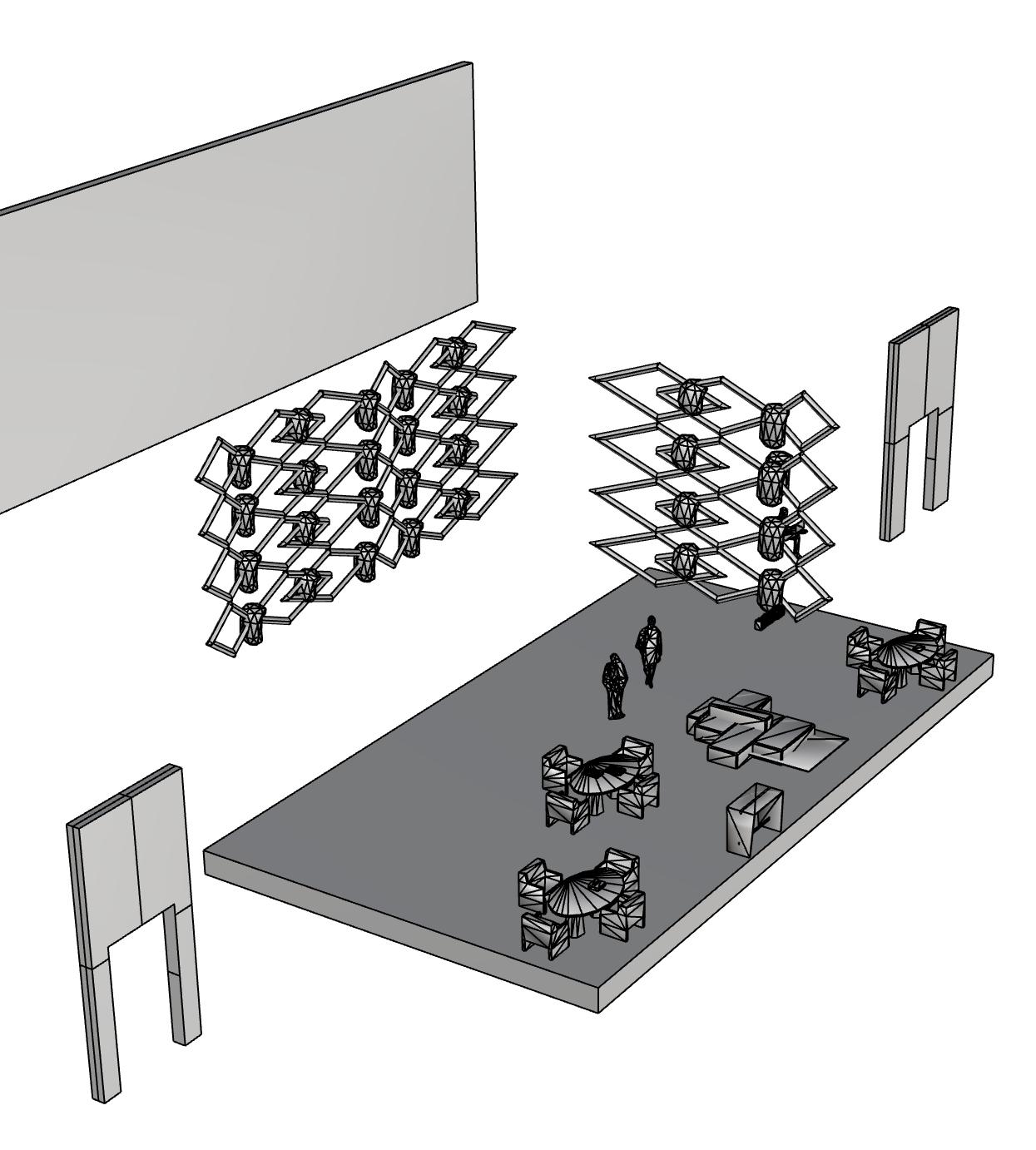
In this series of photos show comparitive axons on how my design can live within in three different spaces. Shown here is how I took the system apart to create three different types of patterns and the axon is the shading device that I decided to use for my first test on how this project can further expand and be used in different spaces.

IMAGE: COMPARITIVE AXONS
SHADING DEVICE FOR OUTSIDE OF BUILDING


STRUCTURAL WALL WITH GLASS SOUND BARRIER
LIVING SYSTEM
When looking at the new designs for proposed spaces the systems are slightly different in relation to the origional design.For the one on the left I just used my 2D pattern and then expanded it onto the beam. For the one of the right I used the first pattern as a layering system to add more depth and took out the beam system.


LIVING SYSTEM
Here live the final rendered images of the final model.

IMAGE: FINAL RENDERED IMAGES

EXISTING LIGHTING
LIVING SYSTEM
Here live the final rendered images of the final model.
WHERE THE PLANTS WILL BE PLACED

IMAGE: FINAL RENDERED IMAGES

LIVING SYSTEM
Here live the final rendered images of the final model.
IMAGE: FINAL RENDERED IMAGES

Here is where I took pieces of the origional design and broke it up into laters. This is one of the layers that I pulled and used as a structural shading device. It can either be its own free standing structure of something that is part of a structural facade of the building.

BUILDING FACADE SHADING DEVICE
IMAGE:
FINAL RENDERED IMAGES

STRUCTURAL SOUND BARRIER
Here is where I took pieces of the origional design and broke it up into laters. This layer is used as a structural sound barrier. The structure will have three layers. One will be the structure you see then a glass panel and then another one of the same existing structure. Here this particular space can be used for office spaces and study rooms.

PLANTING STRUCTURAL WALL
GLASS DIVIDER BETWEEN LAYERS OF THE SYSTEM
IMAGE: FINAL RENDERED IMAGES

STRUCTURAL INBETWEN SYSTEM
Here is where I took pieces of the origional design and broke it up into laters.This scenario shows a structural inbetween living system that can bring mechanics like water and electrical inside the house as well as outside of the house.

IMAGE: FINAL RENDERED IMAGES

Here live the final rendered images of the final model in VR form while looking through a phone using the software fologram.


OFF COLUMN DID NOT COMPLETELY WORK FOR MY SPECIFIC SYSTEM
SPACE NOT COMPLETELY ONTOP OF THE COLUMN WHERE IT NEEDS TO BE


WILL MOSTLY BE CONSTRUCTED WITH 90 AND 45 DEGREE ELBOWS
LIVING SYSTEM
WIthin these last couple images show the material that would suit the growth of the plants that live within my living system. Outlines on the right of those images are the sizing and openings within the digital model that would show how the plants can live within that system sucessfully.


WILL BE A PATTERN OF 12 IN CUT SLITS AND A 12 INCH GAP TO HOLD PLANTS INSIDE


AFTER CONDUCTING LIVE BUILD WILL HAVE TO CHANGE PIPE SIZE FROM .5’’ TO 2’’











45 DEGREE ELBOWS

BRONZE BRACKETS (WOULD BE WHITE IN REAL BUILD)

WOULD BE A V SHAPE IN REAL BUILD USED THE MATERIALS I HAD AND WAS INNOVATIVE
LIVING SYSTEM
To the right show the final physical model with the plants grown within the system.

USED BRONZE TO BLEND IN WITH THE WOOD

IMAGE: PHYSICAL MODEL

USED CHIA FOR TEST GROW SO I USED NETTING TO HOLD IT IN PLACE IN THE PIPE SINCE THE DIAMETER WAS SMALLER THAN INTENDED
LAYER TO KEEP THE PLANTS HYDRATED
LIVING SYSTEM
To the right show the final scaffold with seeds that are begining to grow inside of them.


LIVING SYSTEM
To the right show the final scaffold with seeds that are begining to grow inside of them.


LIVING SYSTEM
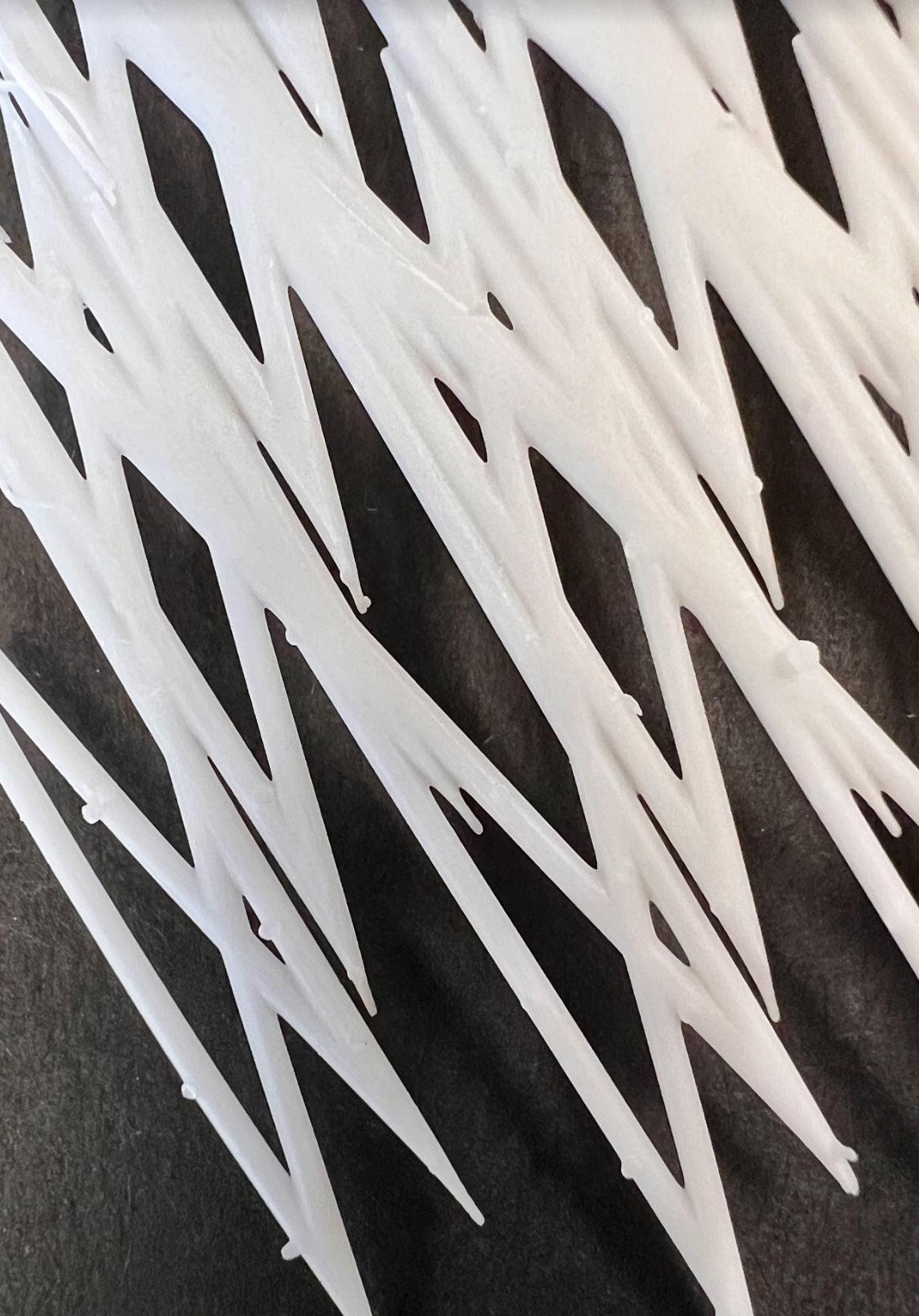
To the right show the final 3D pring of my scaffold.

IMAGE: 3D PRINT OF SCAFFOLD

LIVING SYSTEM
When concluding the research based study there was a lot that I learned throughout this entire process. Coming into this class I did not know a lot about living systems and rhino/grasshopper were not my prefered programs. I was super excited to do a reasearch based program and learned more than I have from any other studio. The process was intense but it was cool to use need technology to create our scaffold and utilize 3D printing to make this project hands on. The rhino and grasshopper scripts that were use were informative of how intense it is to create a sucessfull living system, since it comes with so many issues, and people do not properly take care of them. Everything that was used I will carry on and use throughout my architecture career and am thankful to have participated in this upcoming research.

IMAGE: FINAL SCAFFOLD IMAGERY
