POMPIDOU 2
BIOFILIA IN THE BUILT ENVIRONMENT
TAITE MCLOUGHLIN

BIOFILIA IN THE BUILT ENVIRONMENT
TAITE MCLOUGHLIN
My name is Taite McLoughlin and I’m a second year MArch student at the University of Oregon. This quarter I’m focusing heavily on environmental analysis and trans-species design. In this course, my focus is plants, but in my other course, I am working with the same programs to develop habitats for native bumble bees.
My undergraduate degree was a double major in math and art with a concentration in sculpture. Sculpture turned me into a very creative problem solver that thinks
efficiently in three dimensions. I ended up working significantly with digital fabrication methods and exploring the applications of laser cutting and 3D printing in sculpture. This has been a huge influence on my workflow in Architecture and my model making methods.
Previously, I have designed more traditional architectural projects exploring large timber construction in a furniture building school and balancing double height spaces in multistory buildings in a school of music and dance with classrooms and performance spaces.
Most recently, I designed a modern
workplace to entice people to return to the office environment after COVID forced us all home. This exploration was being guided by a workflow laid out by my professor that touches on every aspect of design from program and concept to site selection and definition of space. I enjoyed the customization of this studio as I got to work on a building for a company I chose and had a personal fondness for its products.
I currently work at the college of design IT desk which, for someone with no computer background, has been a challenge in learning new skills on the job. However, I’m a very proficient Googler,
so I never let a roadblock get me down. I was recently promoted to Lead Student Technician which has allowed me to utilize my design and organization skills in creating workflow documentation and management systems.
Because of my creative background, I really want to work in civic and community architecture designing libraries, museums, and spaces where a more playful, colorful environment is appreciated.
Intro Statement
Material Phase
PATTERNING FROM NATURE
INITIAL TESTING
FINAL PRINT
SEED SELECTION
Research Phase
SITE SELECTION - DRAWINGS
ENVIRONMENTAL CONDITIONS
Component Phase
PHYSICAL MODEL STUDIES
PROPOSED DESIGN
PLANTING - LIGHT DATA
WATER FLOW/DRAINAGE
Prototyping Phase
IDENTIFYING NATURAL SCAFFOLDS
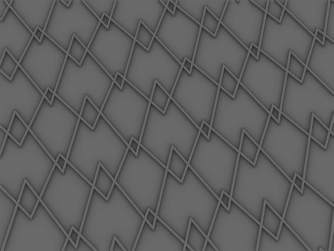
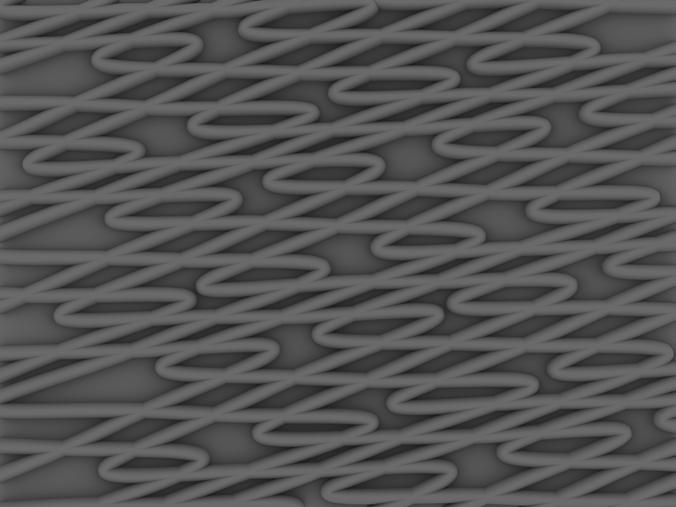
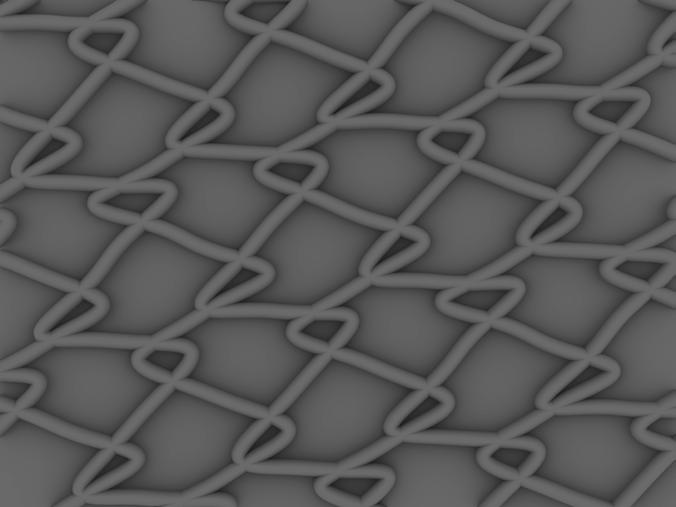
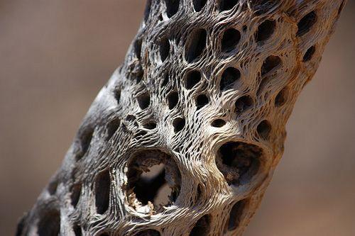
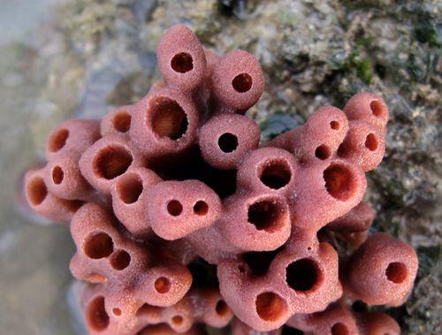
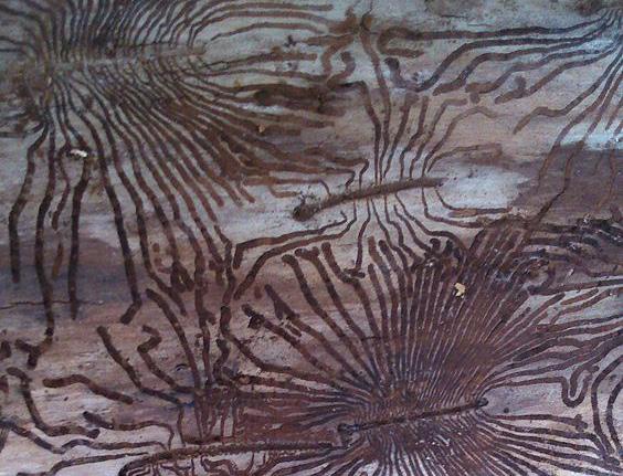
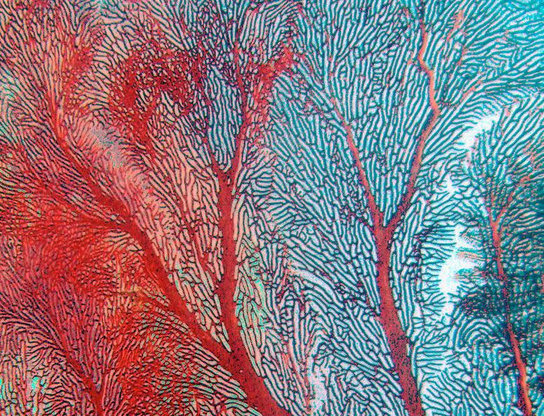
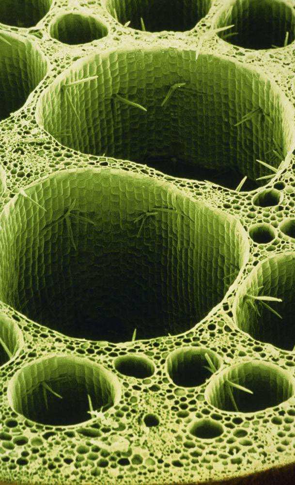
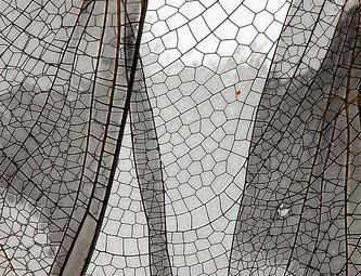
Our first task was exploring and finding inspiration in nature and seeing what patterns emerge and inspire us. On the right side of this spread, you’ll see the patterns that inspired me. Most importantly, I was inspired by the space packing properties of plant vascular systems and how that correlates with the transport of nutrients. I wanted to capture that variation in opening size in my scaffold to allow for a surface that roots can adapt to and find their desired growth pattern as they would in soil.
Grasshopper is an algorithmic programing language that can be used to analyze, populate, and change geometry in Rhino (a 3D modeling software) to fit necessary parameters of the design. I focused on creating a overlapping grid system that had a variety of spaces between fibers.
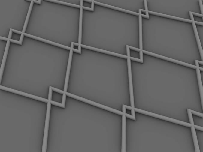
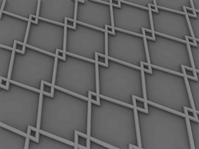
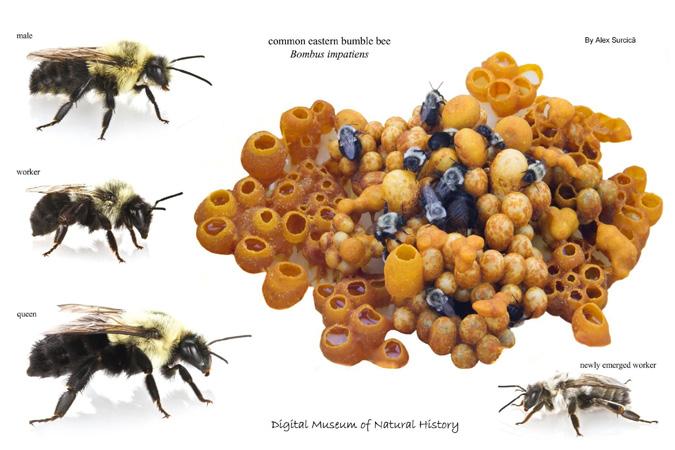
Top Left: bumblebee nest cluster
Top Middle: coral, bulbous
Top Right: lily-pad root section
Middle Left: cactus skeleton
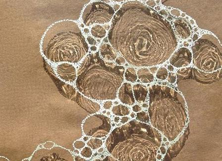
Middle Middle: bubbles on water
Middle Right: lily-pad root section, cont.
Bottom Left: beetle burrows in wood
Bottom Middle: coral, linear
Bottom Right: dragonfly wing
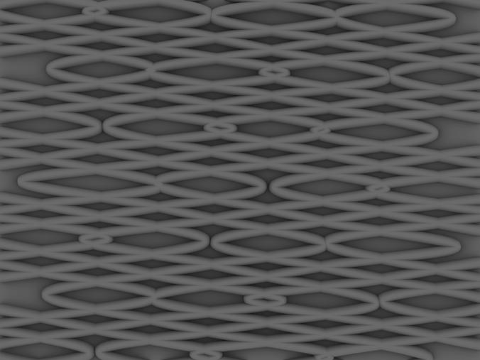
After our digital pattern exploration, we printed small or low layer count tests of the prints we were most excited to see in its physical form. In an effort to obtain even more variation in the texture of my designs, I asked for them to be printed at a slower speed to create a frothy texture.
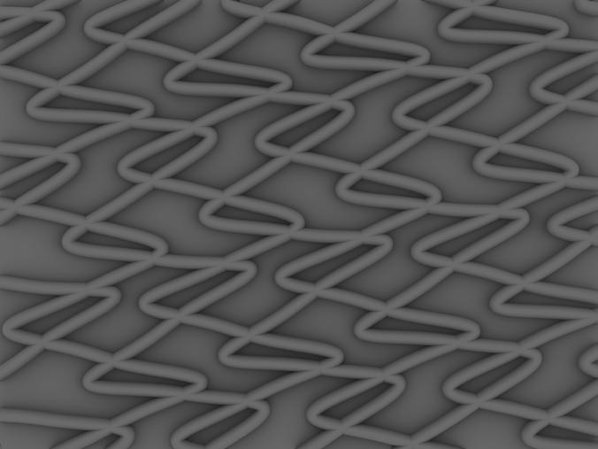
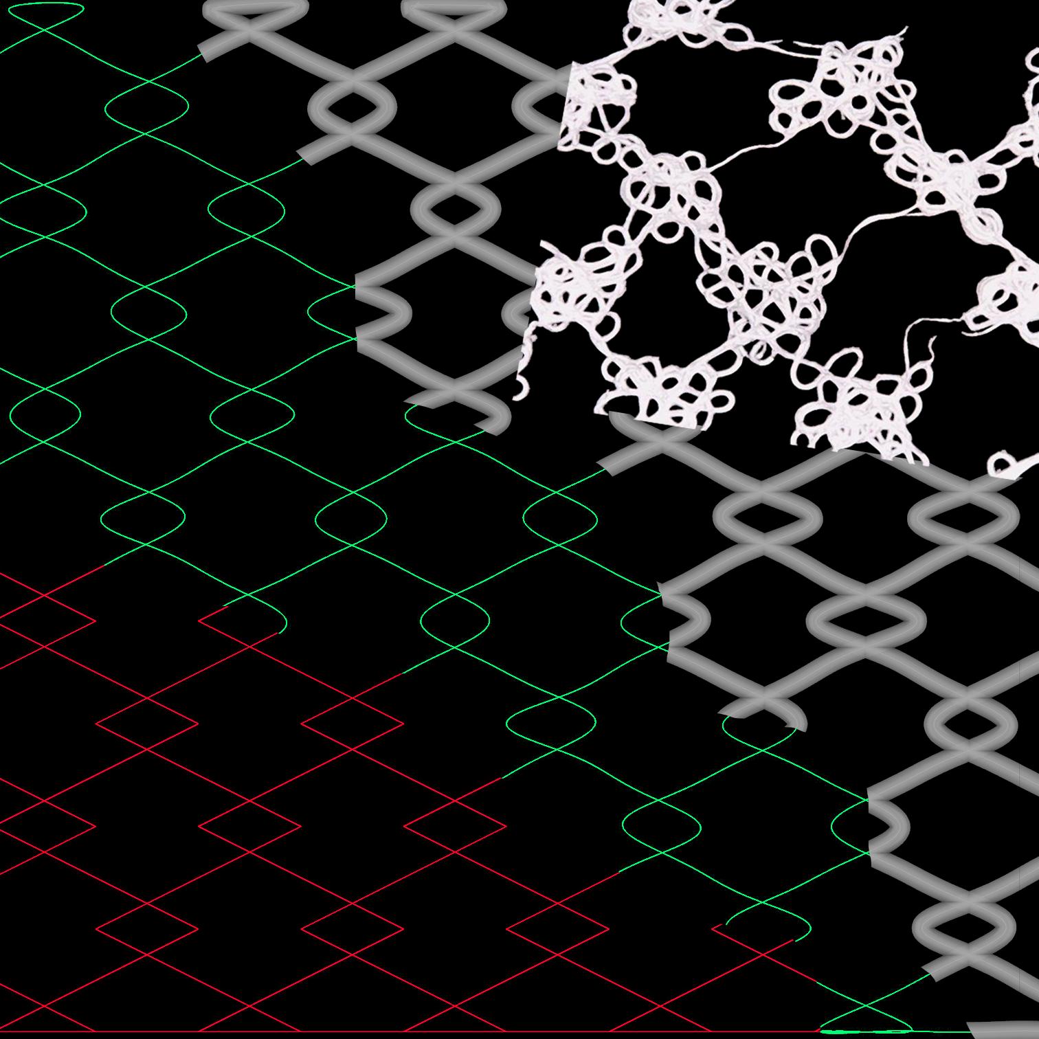
Each of the diagrams in this spread illustrates the complete design process of my test scaffolds. The red line shows how the pattern looks in Rhino from running only the initial patterning code. The green shows an estimate of the actual path the printer will take as there is a slight lag between the nozzle and where the polymer lands. The grey layer is a rough render of the resulting scaffold. The white is what is actually printed with extra loops and complexity from the print speed being adjusted.
PROGRAMMED PRINT PATH
APPROX. ACTUAL PRINT PATH
APPROX. FILAMENT PATTERN
ACTUAL PRINT
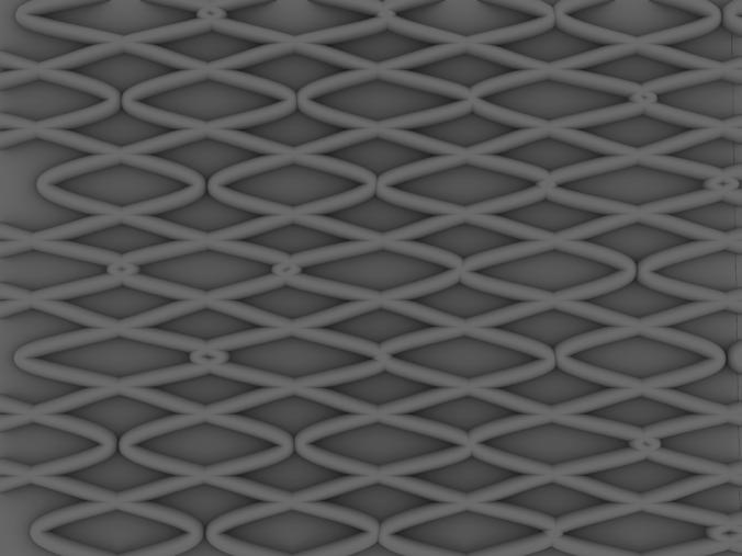
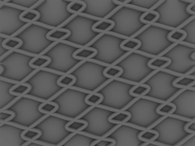
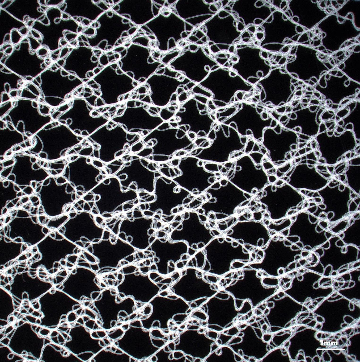
This diagram illustrates the pattern I ultimately decided to move forward with.
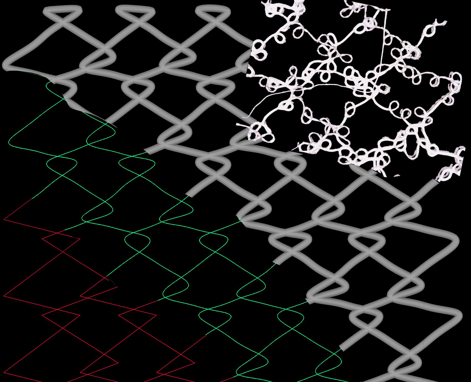
IMAGE:
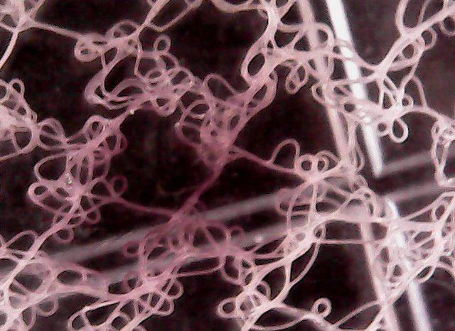
Final pattern printed 90mmx90mm 1mm grid
PRINTING AT FULL SCALE
Once a final pattern has been chosen or designed, it was sent to Naomi, our knight campus contact, to be printed at full scale (90mm x 90mm). These scaffolds took about a week to come back to us and were shockingly strong when handled. My bubble pattern had very little stretch compared to some other patterns and the extra material from printing as a slow speed made it very strong.
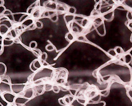
Zoomed in shot of a module in my final pattern.
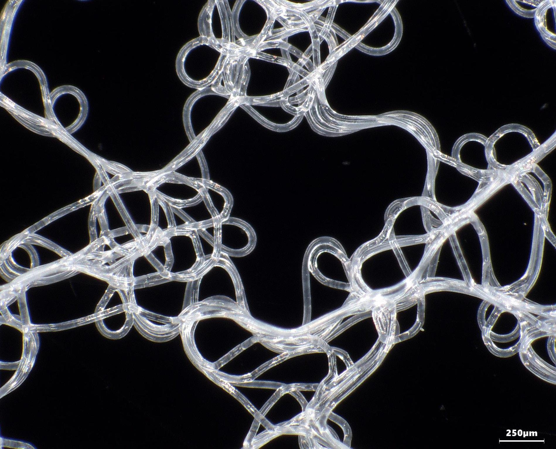
IMAGE:
First visible root growth in GelXan
As I was designing this scaffold, I was struck with the idea of tiny green walls and wanted to explore their use with herbs as I hope to install mine in my kitchen. I planted basil and cat mint for this experiment as they have small seeds and strong roots that should allow them to thrive on the scaffolds.
Here you can see seeds beginning to root on the final scaffold (left) and roots weaving between the layers of material after two weeks of being planted (right).
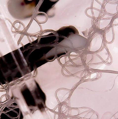
IMAGE:
Root growth through scaffold after 2 weeks
DECIDING ON INSTALLATION SITE
Lawrence hall is home to the entire College of Design and, therefore, showcases many installations of student work. With University of Oregon’s focus on sustainability, it would make sense to showcase the newest in living systems. Thus, Lawrence Hall became our site.
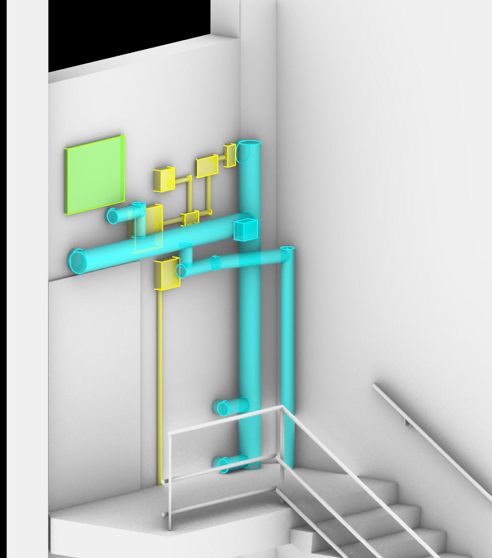
The northern stairwell in Lawrence Hall is shockingly architecturally activated with high ceilings and a large southern clerestory window. I often see students using the space to make phone calls and it’s the primary route between Lawrence’s primary spaces on the second floor and the studios on the third and fourth floors. For all the obvious care that went into it’s form, the finishings of the stairwell are bland and stark. With visually confusing visual piping for emergency systems. This made it the ideal site for an overhaul of visible infrastructure.
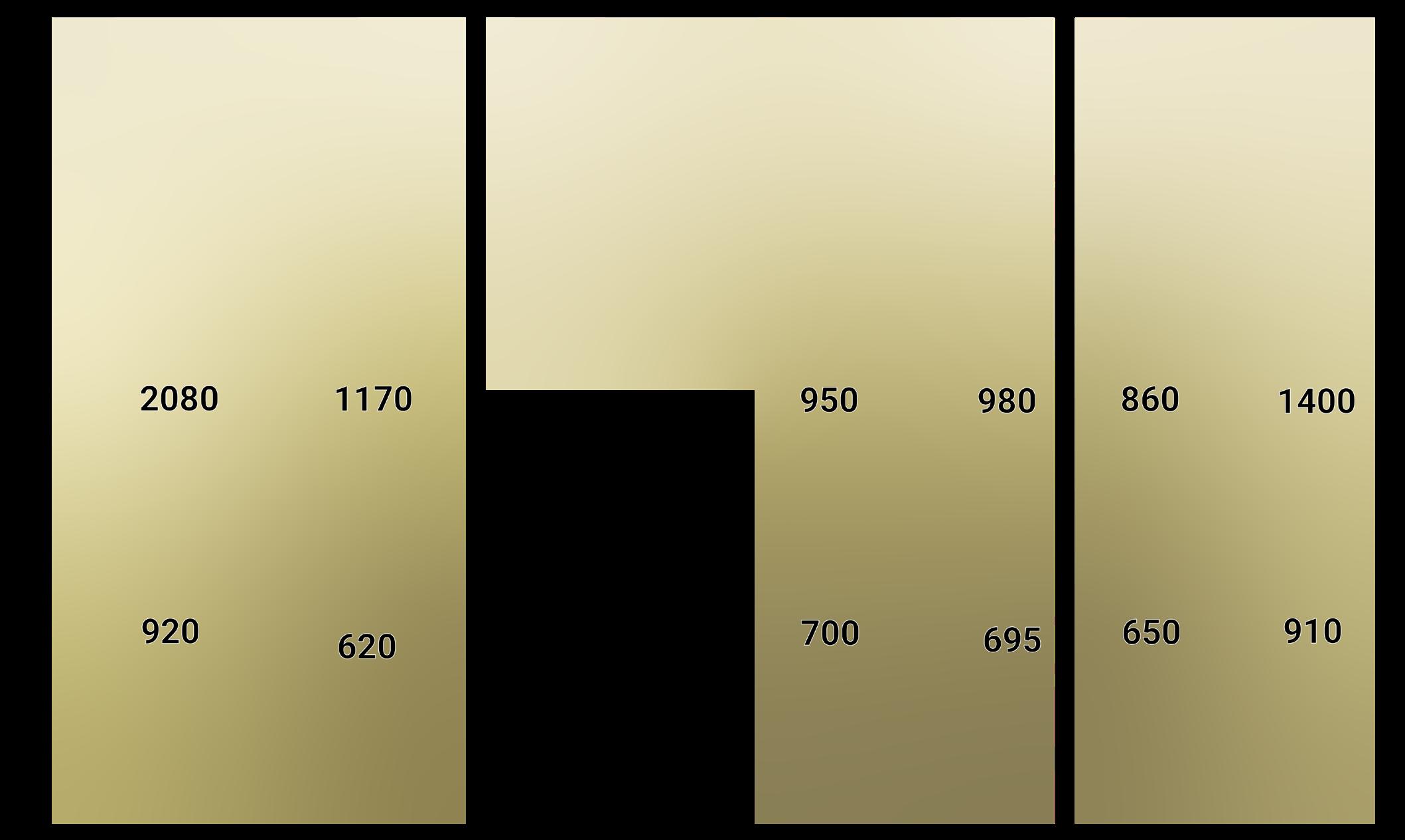
I focused my study on the top landing which is ten feet wide at its northern edge and is beveled at the southern corners to just over nine feet. It is five feet deep from door to stair. In terms of explorable vertical space, I limited my height to thirteen feet to reach the base of the upper window without impeding light to the plants that will come later.
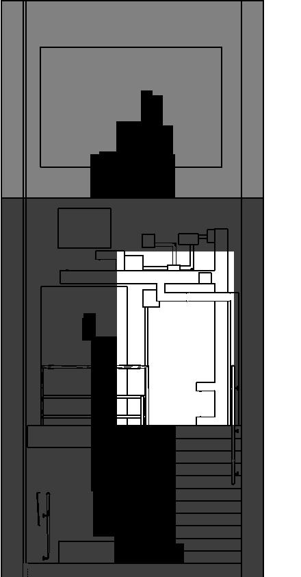
IMAGE: Plan of space with dimensions
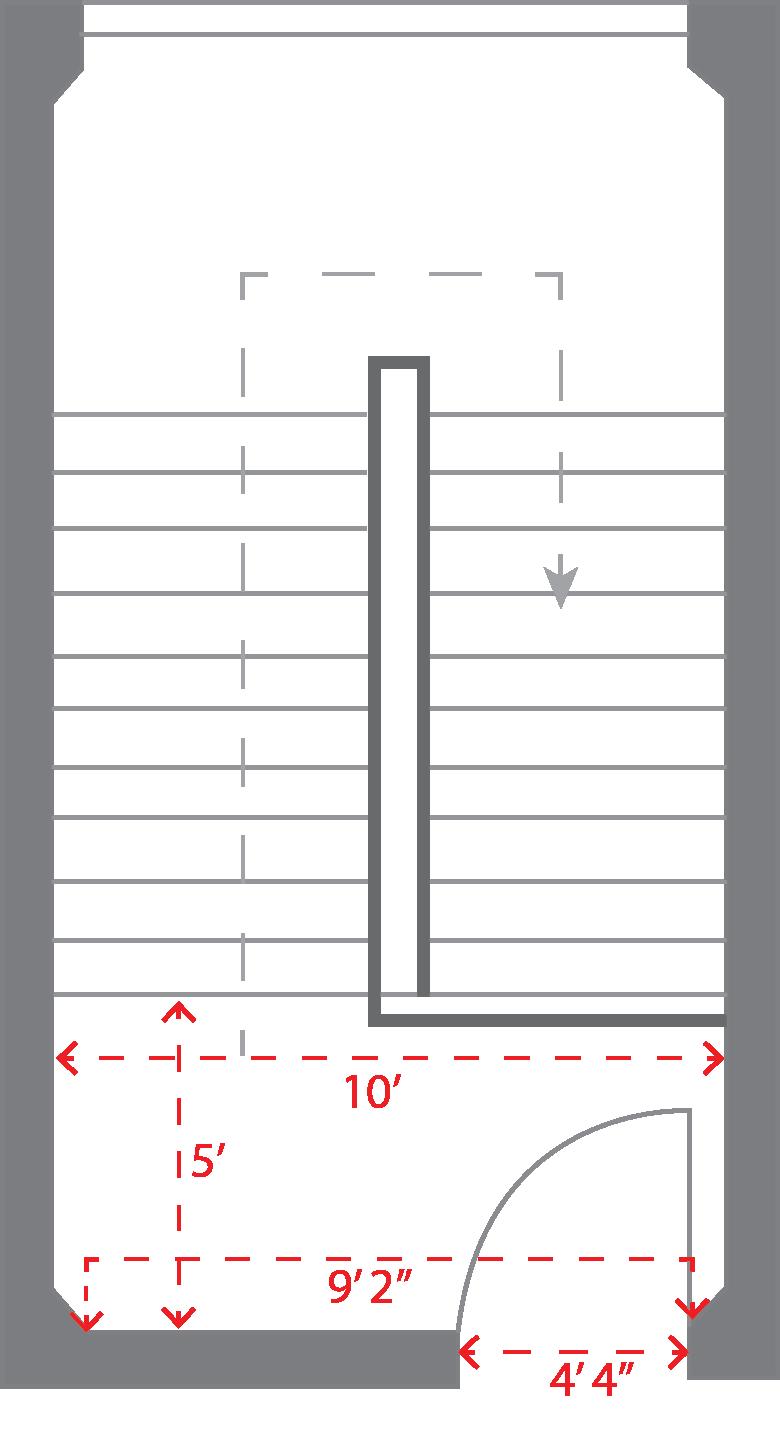
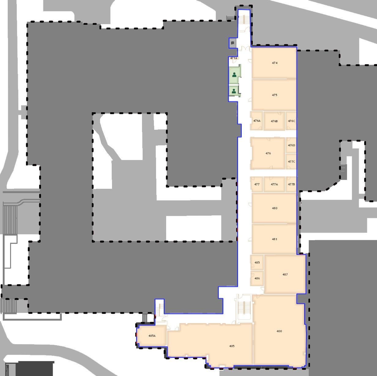
IMAGE:
Map of Lawrence with site highlighted
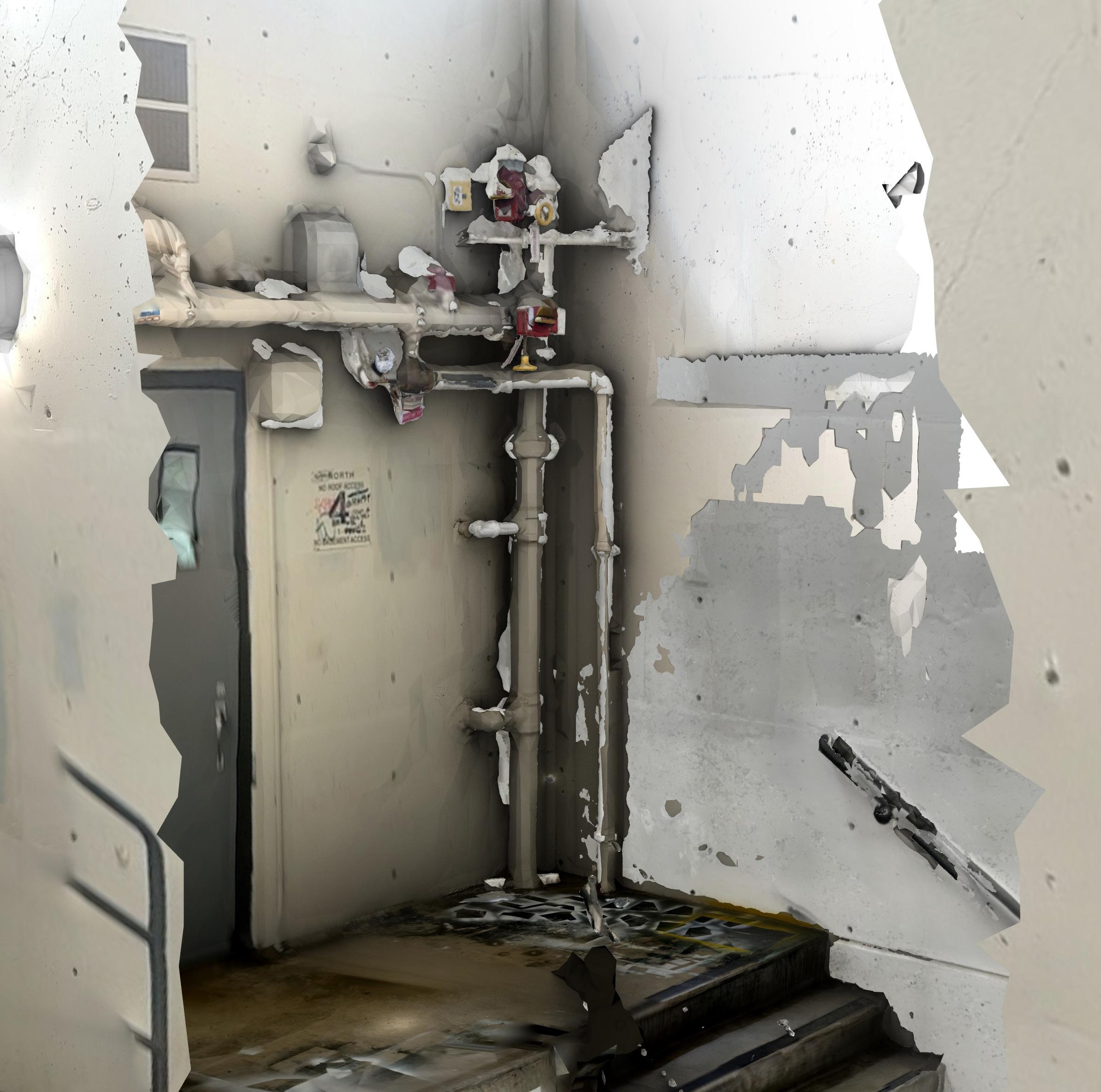
IMAGE: Combo Lidar and Photogrammetry model
VISUALIZING OUR PROJECT SCALE
My space has access to water through the sprinkler main. This would not be legal in real life, but exploring how this would work theoretically is extremely helpful. What struck me about this space is the visual impact of the plumbing. It reads as an afterthought and it could be activated in a much more visually pleasing way.
The first method we explored for digital modeling was using our phone cameras to take detailed photos of our space and using Metashape to align the photos and generate a 3D model of the space.
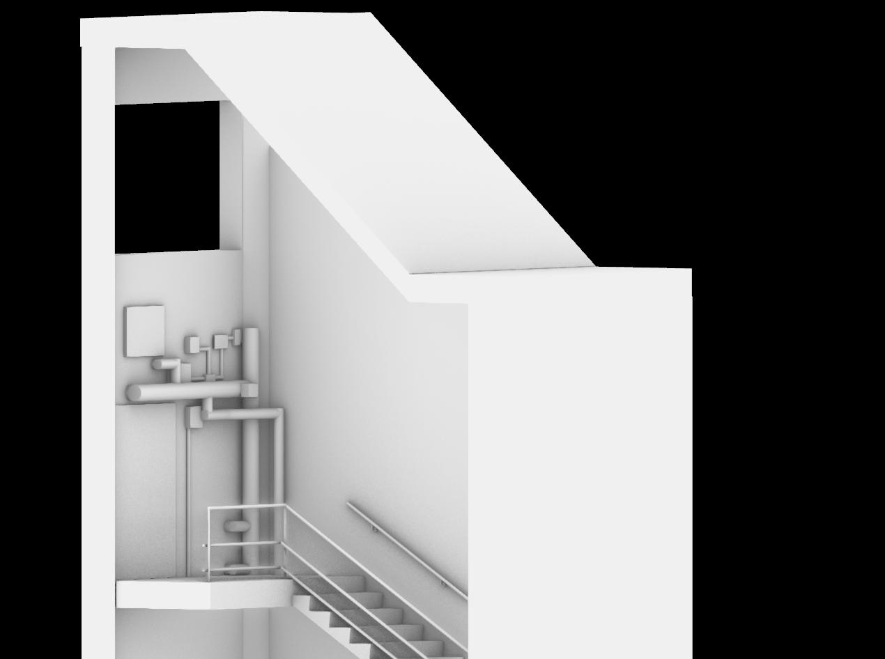
The photogrammetry model is great for initial modeling and space visualization, but isn’t very clean and is difficult to build into. Therefore, our next step was to build a clean model based on the dimensions of our space that we could use as the base of our design.
Digital twin of space and physical model of existing space (1/2”=1’)
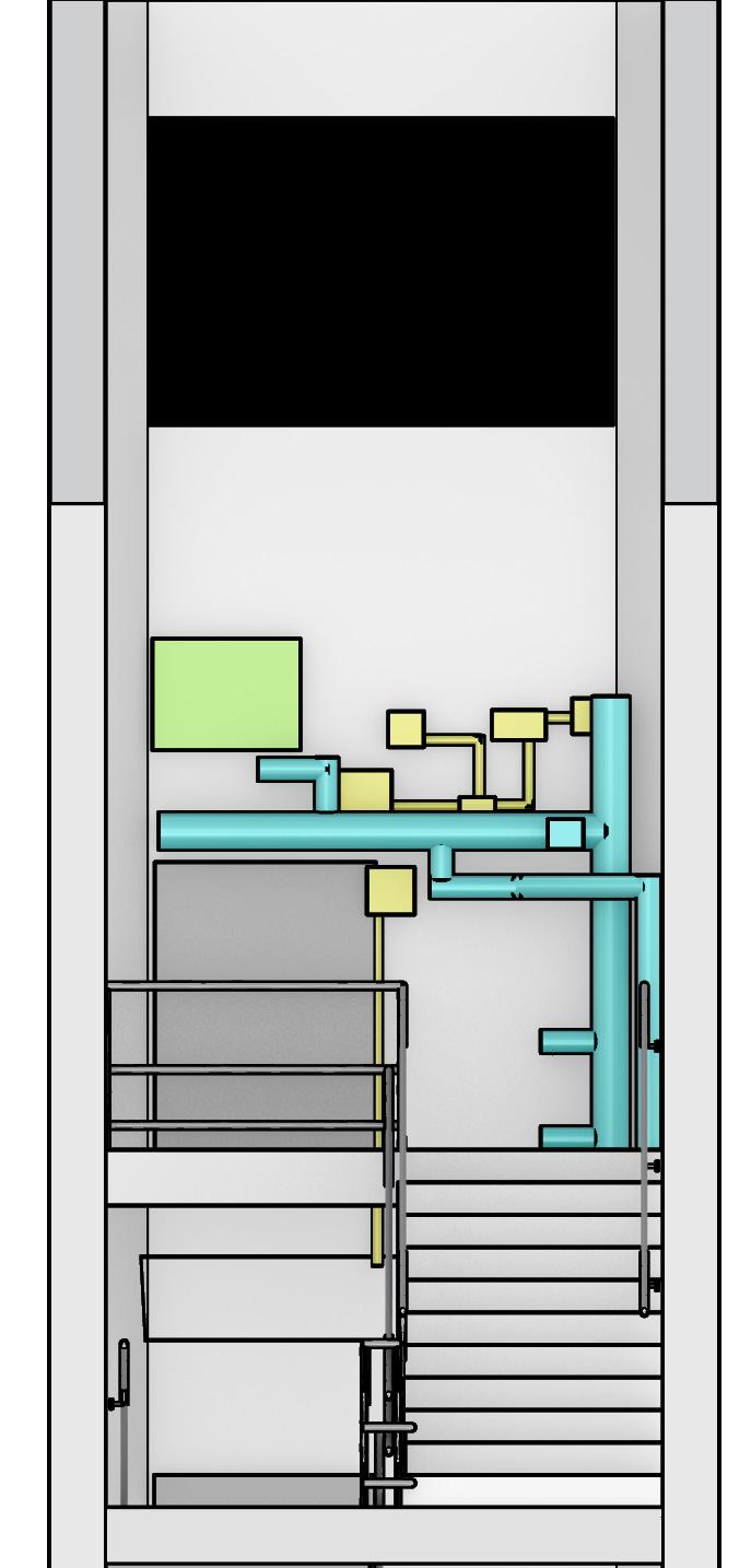
MECHANICAL AND ELECTRICAL SYSTEMS
As previously stated, it would not be legal for me to tap into the sprinkler main that serves as my water source in the space. However, I am going to move forward as if it were legal which allows me to hypothetically take advantage of the high pressure sprinkler systems are under to push water upward into systems that don’t line up with the horizontal piping.
HVAC
There is a vent that comes in just above the door in the stairwell that would allow me to access the HVAC system to control humidity. However, there are also operable windows in the space that can more economically be utilized instead.
ELECTRICITY
The electricity in the space is also for the emergency system and cannot by tapped into in real life, but I persist. Additional lighting will be needed as will be shown later in the booklet.
EXISTING ELECTRICAL
EXISTING HVAC
EXISTING PLUMBING
IMAGE:
Digital twin with systems highlighted
SOLAR EXPOSURE
An bright overcast day in Oregon is approximately 1000 lux
I used the lux meter to see where the brightest part of the stairwell is. As the main light in the space is southern-facing, but very high up, I was worried about plants not getting enough light. I took my first readings at around 1:30pm January 29, 2023 which turned out to be a very bright winter Sunday. From this data, I should populate my scaffold with bright, indirect sunlight attracted plants.
To compare this data to a more overcast day, I took additional data on an overcast day in March (3/5/23) at 2:40pm. This data actually showed the brightest landing to be the lower with northern light. The difference was not so great, however, that I would change my planned location for my installation.
IMAGE:
Lux data from 2:40pm on Mar 5,2023 Bright, overcast weather
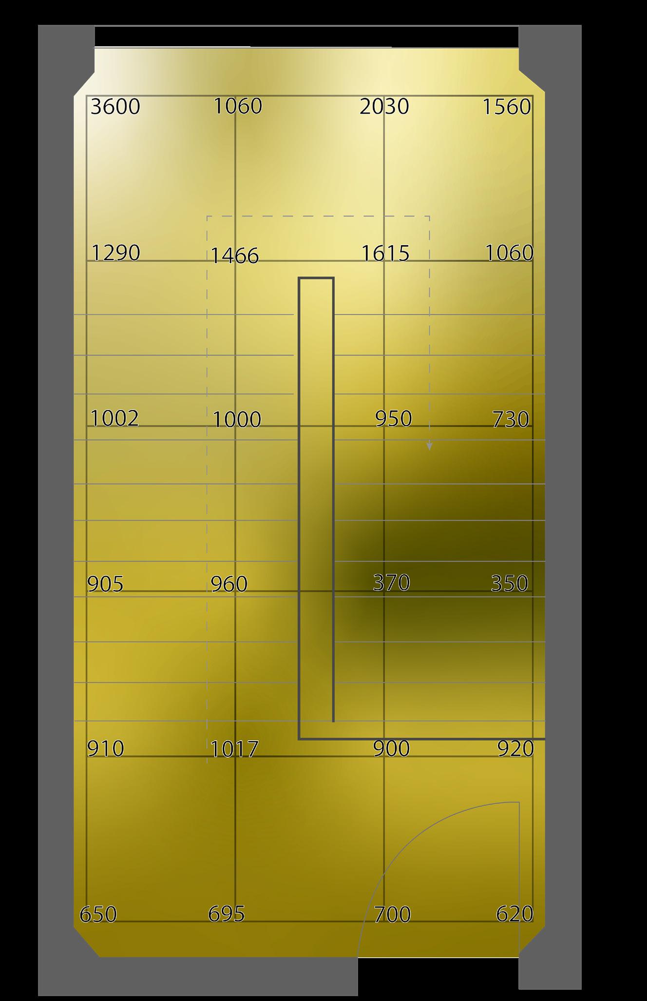
IMAGE:
Lux data from 1:30pm on Jan 29,2023
Bright, sunny weather
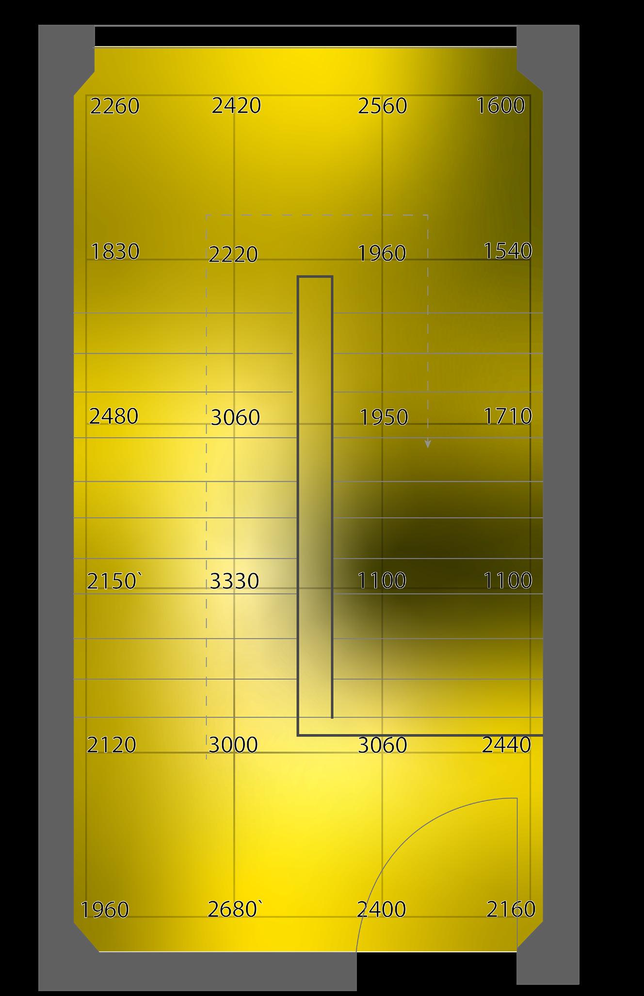
IMAGE:
Lux data from 6:30pm on Jan 29,2023
Measures only artificial light
PHYSICAL MODELING
Since the pipes of our installation all have to interconnect, we first modeled them using string and a pattern of nails. By using long nails and excess string, I was able to explore depth and density of layers on top of pattern with this model.
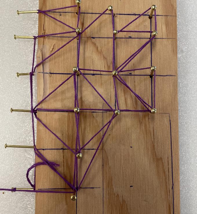
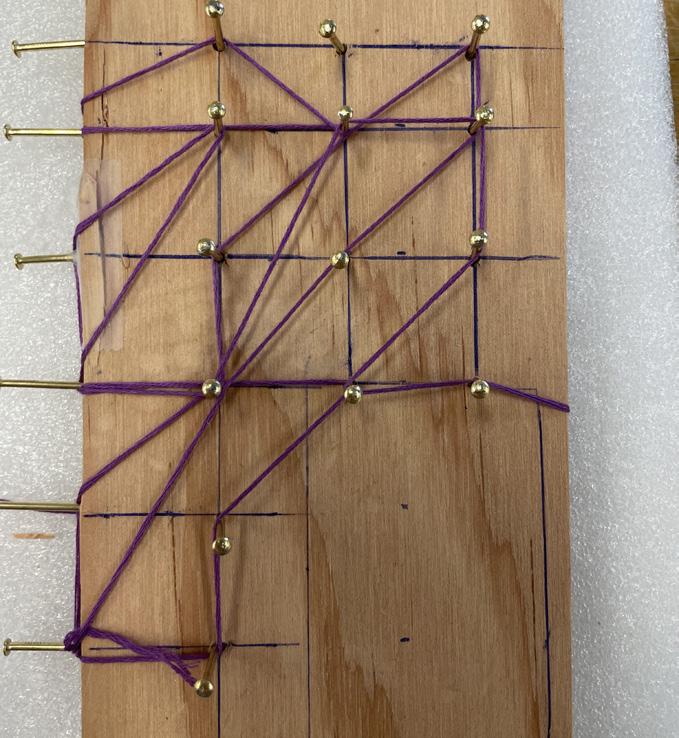
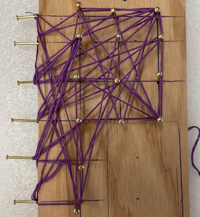
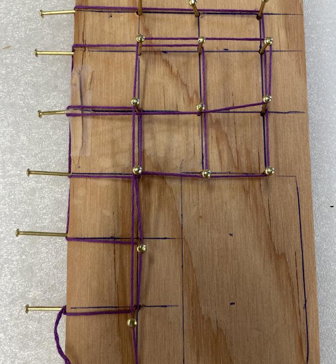
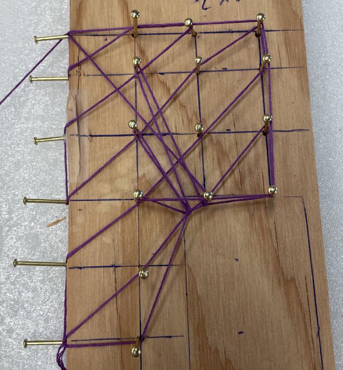
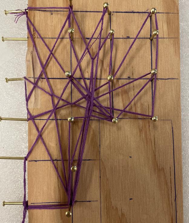
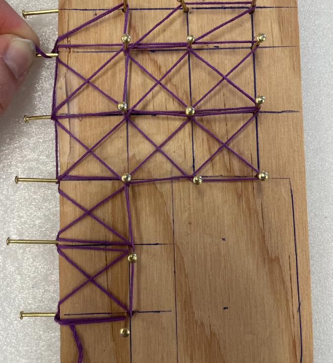
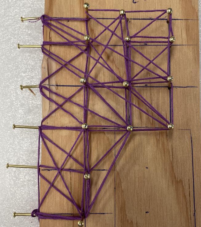
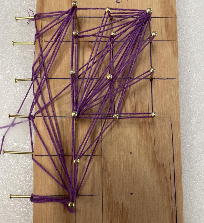
These are the two models I was most interested in pursuing
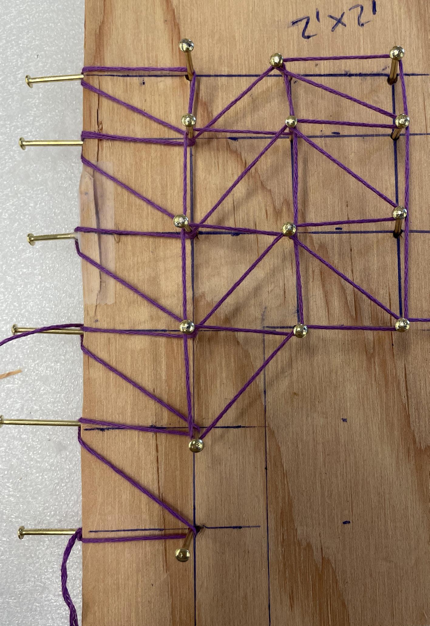
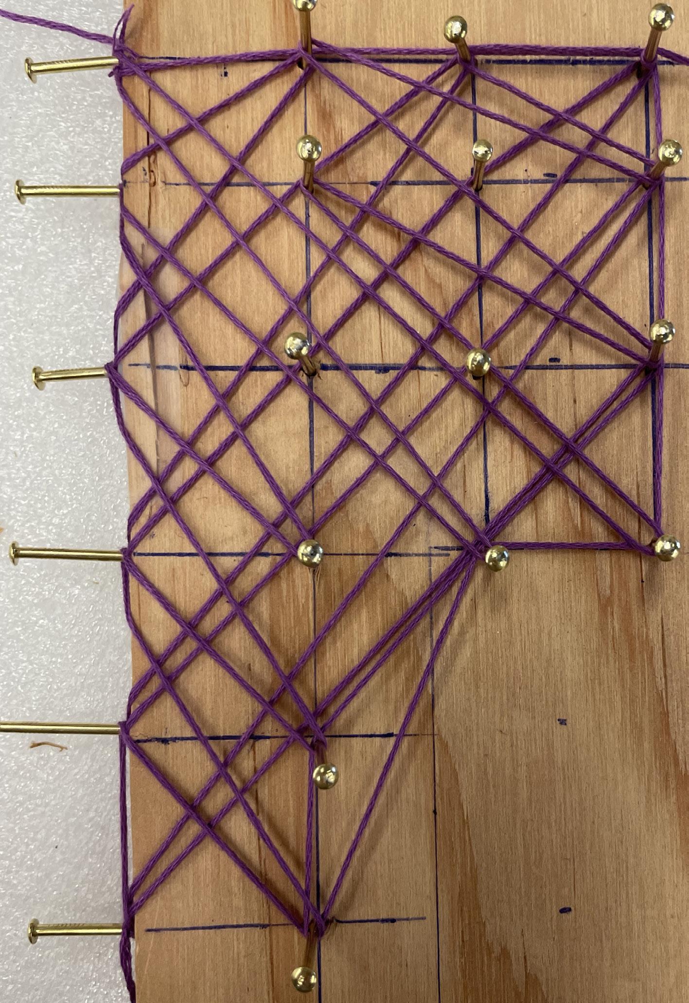
IMAGE:
Top: Module blocks
Bottom: Blocks on exploded elevation
DIGITAL MODELING
DEFINING MODULES
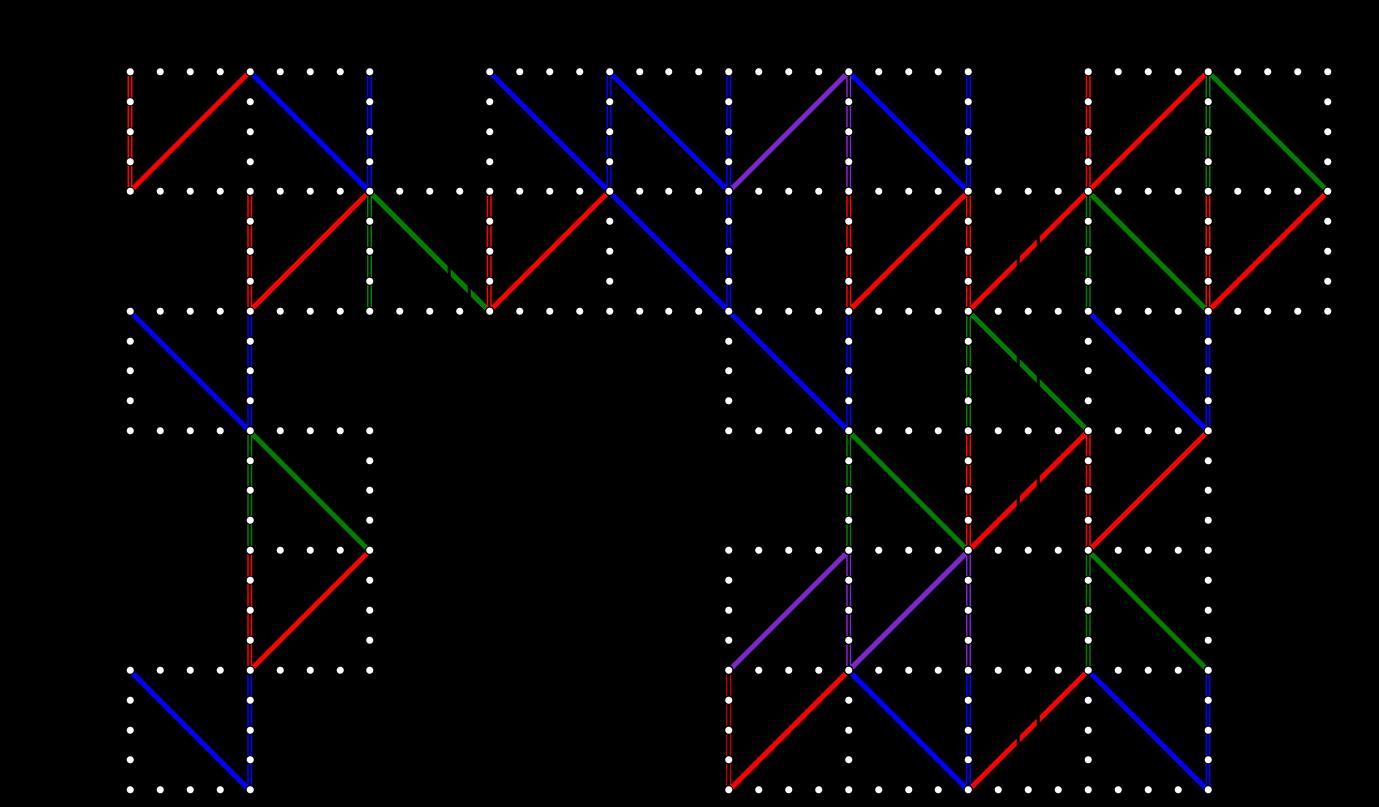
From my string model, I realized a triangular module was the most practical being easy to install and construct in the space. I defined 4 triangle modules in various orientations and iterated them across an exploded elevation of the space.
In order to work around the existing plumbing and add more complexity to my model, I changed the height of each row of triangles and adjusted individual nodes as needed so the scaffold fit seamlessly into the existing space.
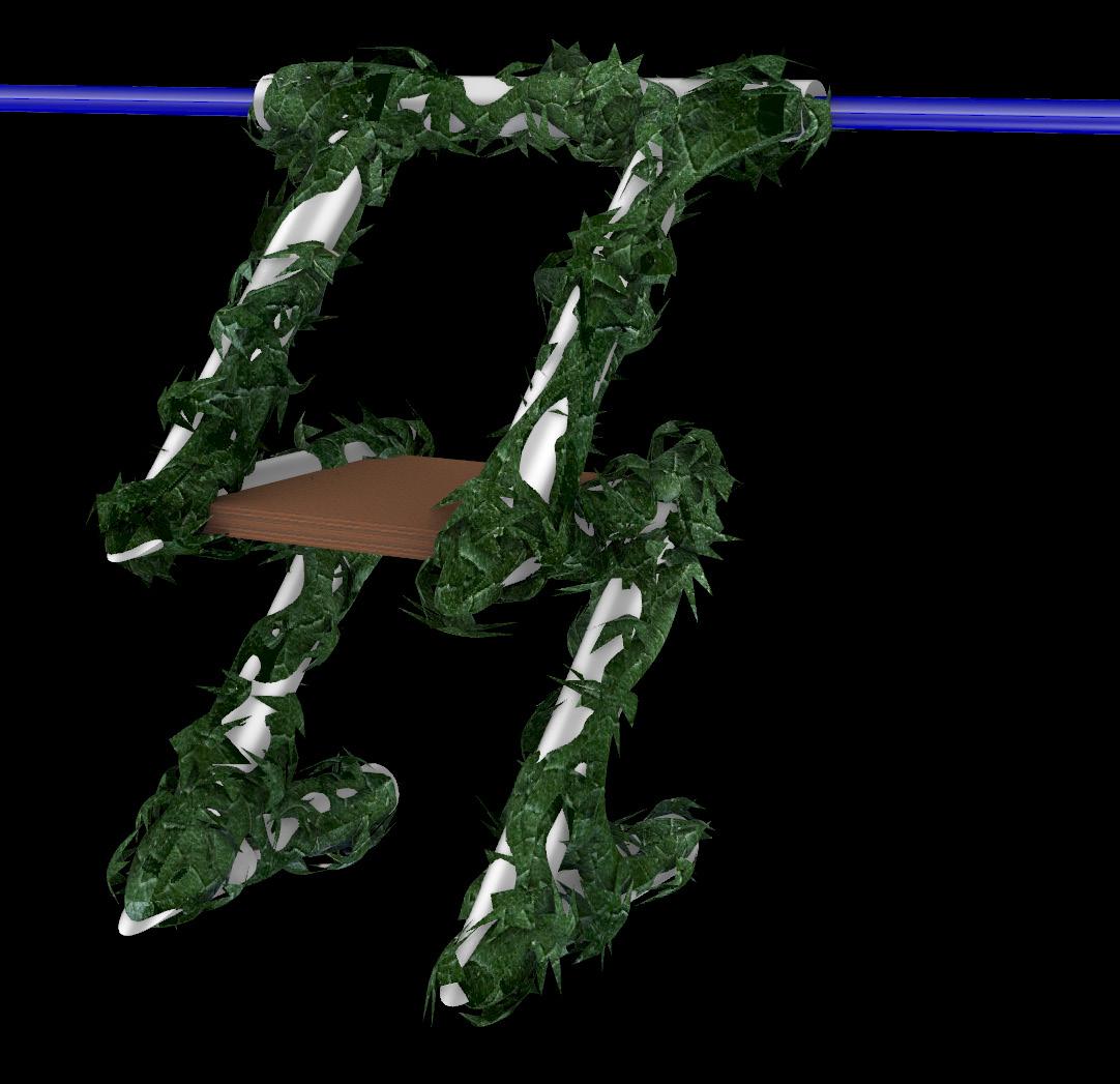
Once the base of the structure has been defined using curves, grasshopper was once again utilized to simulate how the structure will look when made out of tubing to deliver water to the plants. This was a very finicky process and I’ve included some of the failures I ran into as I found the proper diameter and connections for my tubing.

Left: Curves with dimension
Right: Pipe model of proposed design
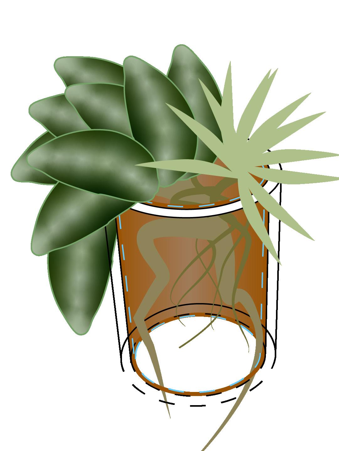
I sized my pipes according to the root size for climbing fig (Ficus pumila) and modeled them at four inches in diameter to allow the saplings to be planted directly into the exposed ends of the tubes. The connections at the top of the structure can also be modified to allow more sprawling plants.
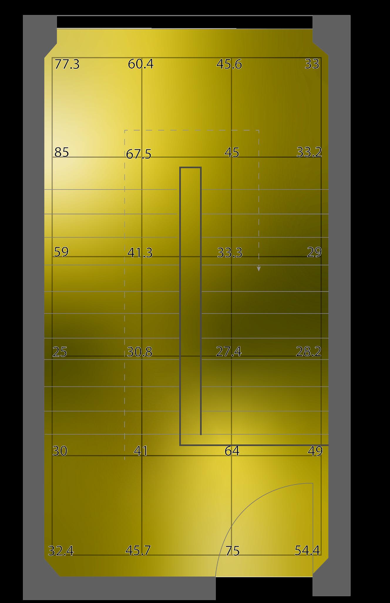
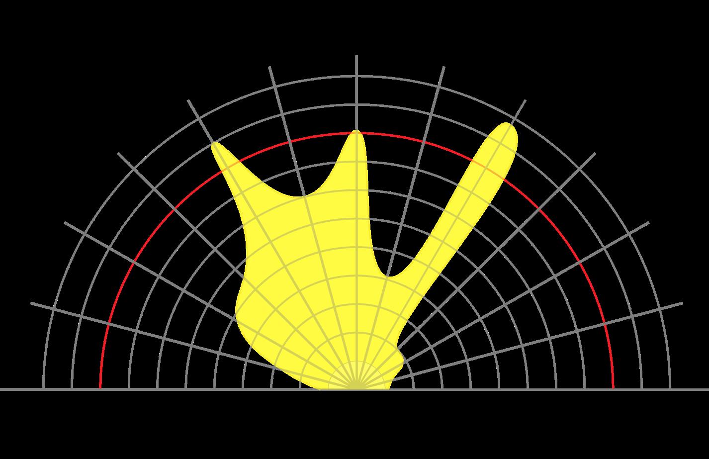
On the right side of this spread, I put both a visualization of the lux data that I obtained through personal tests and the Grasshopper approximation of annual solar exposure done digitally. Both of these tests suggested that plants should be placed on the top of the structure. I immediately thought to install vining plants that could trail down the side of the structure. Additionally, this data showed that the Hoya would do best on the eastern wall as it has the most solar exposure.
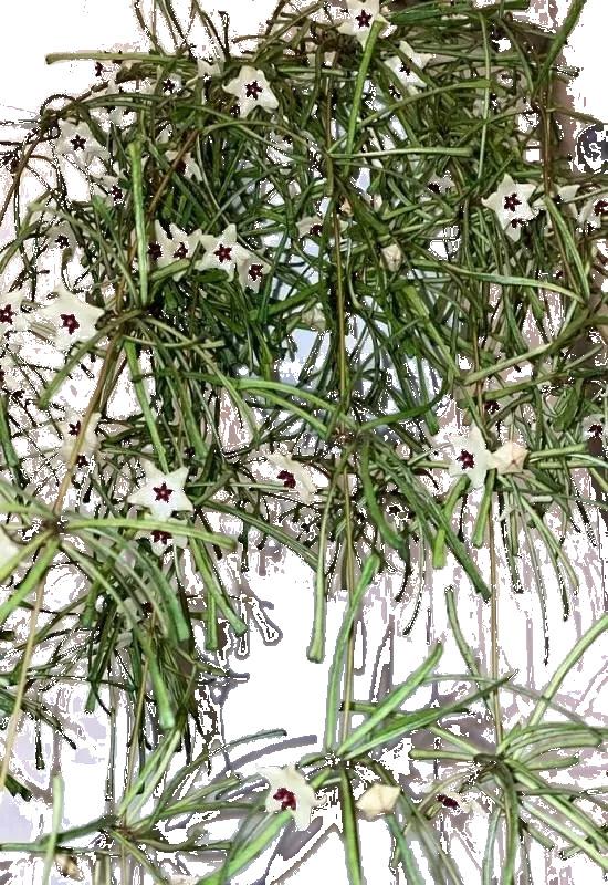
I knew I wanted to install vining plants that could use the interior of the scaffold for root growth and the exterior as a trellis to wrap around. Based on my lux data, I went for plants that thrive in bright, indirect sunlight and found Creeping Fig and Hoya Retusa. After analyzing their particular lighting needs (see table to the right), I confirmed that additional lighting would be necessary in the space.
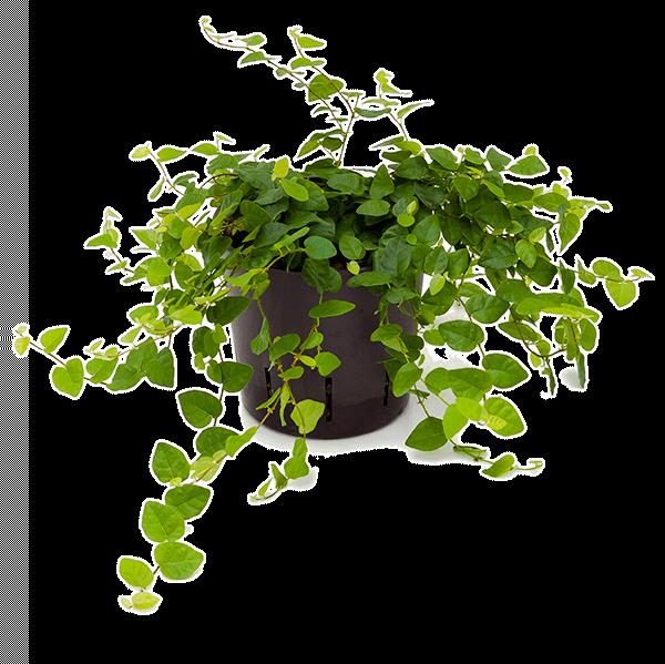
IMAGE:
Top: Plant choices and floral symbols
Bottom: Planting diagram by light level

LEAST SOLAR EXPOSURE
MOST SOLAR EXPOSURE
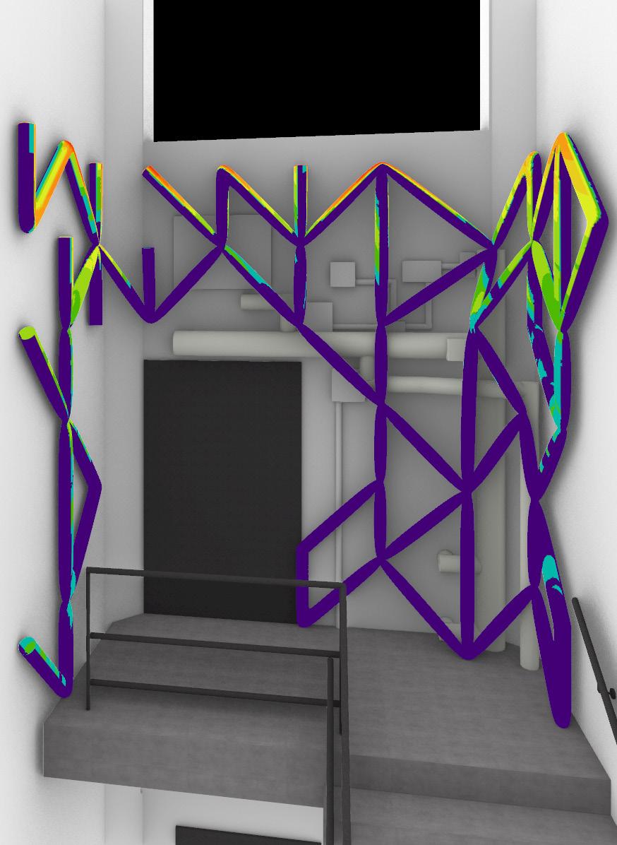
IMAGE:
Left: Modeled solar exposure Right Top: Lux needs calculations
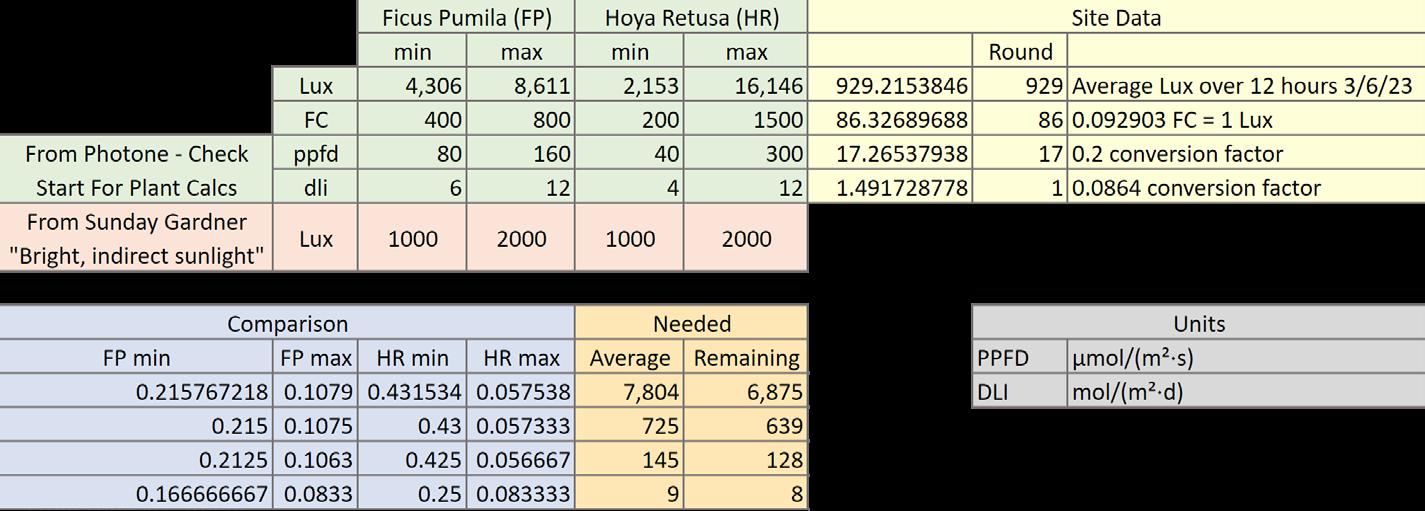
IMAGE:
Measured lux data March 3, 2023 6:40am to 6:40pm
WATER FLOW ANALYSIS
My plan is to tap into the top of the sprinkler pipe to water the substrate from the top and allow it to drip down the interior of the pipe system with the roots. The water will travel down the central line of the vertical structure and drain through two catch trays at the base.
There are certain points on the model where pooling occurs due to the nature of the triangular system. Instead of adding more piping and changing the lines and aesthetics of the modules, cotton cording can be strategically placed into the tubing and bring water back up to drainage paths naturally. These points of intervention are marked on the exploded elevation seen directly to the right of this text.
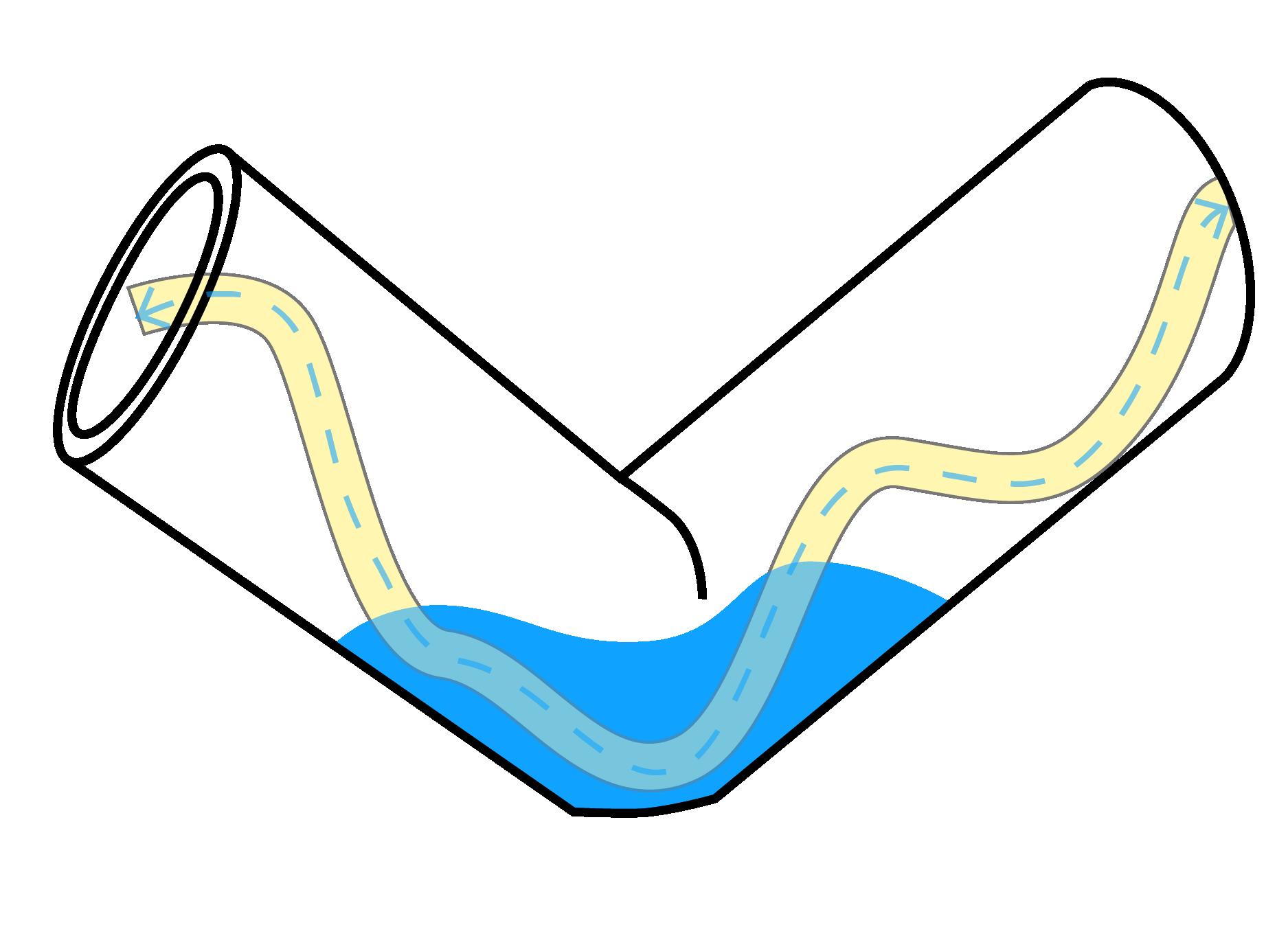
IMAGE:
Top: Diagram of wicking through cord
Bottom: Exploded elevation wicking diagram

IMAGE:
Left: Water supply and drainage system
Right: Grasshopper simulation of flow
NEW SYSTEMS OPTIONS
By activating the landing with new lighting and planting. A more rounded user experience is created and the exposed systems become a visually pleasing bridge with the outside world teased by the window above.
After analyzing the current lighting conditions and finding them to be insufficient, I took the suggestion from my midterm review of installing strip lighting in a way that mimics the structure of the scaffold itself to allow the vines to trellis around the lights and seek them at whatever angle necessary. These lights would have to produce about six thousand lux to fully satisfy the plants’ needs.
Another method for bridging this lack of lighting would be to install new windows on the eastern and western walls on the same level as the southern window. You can see in the modeled solar exposure render to the right that these new openings dramatically change the light that hits the structure.
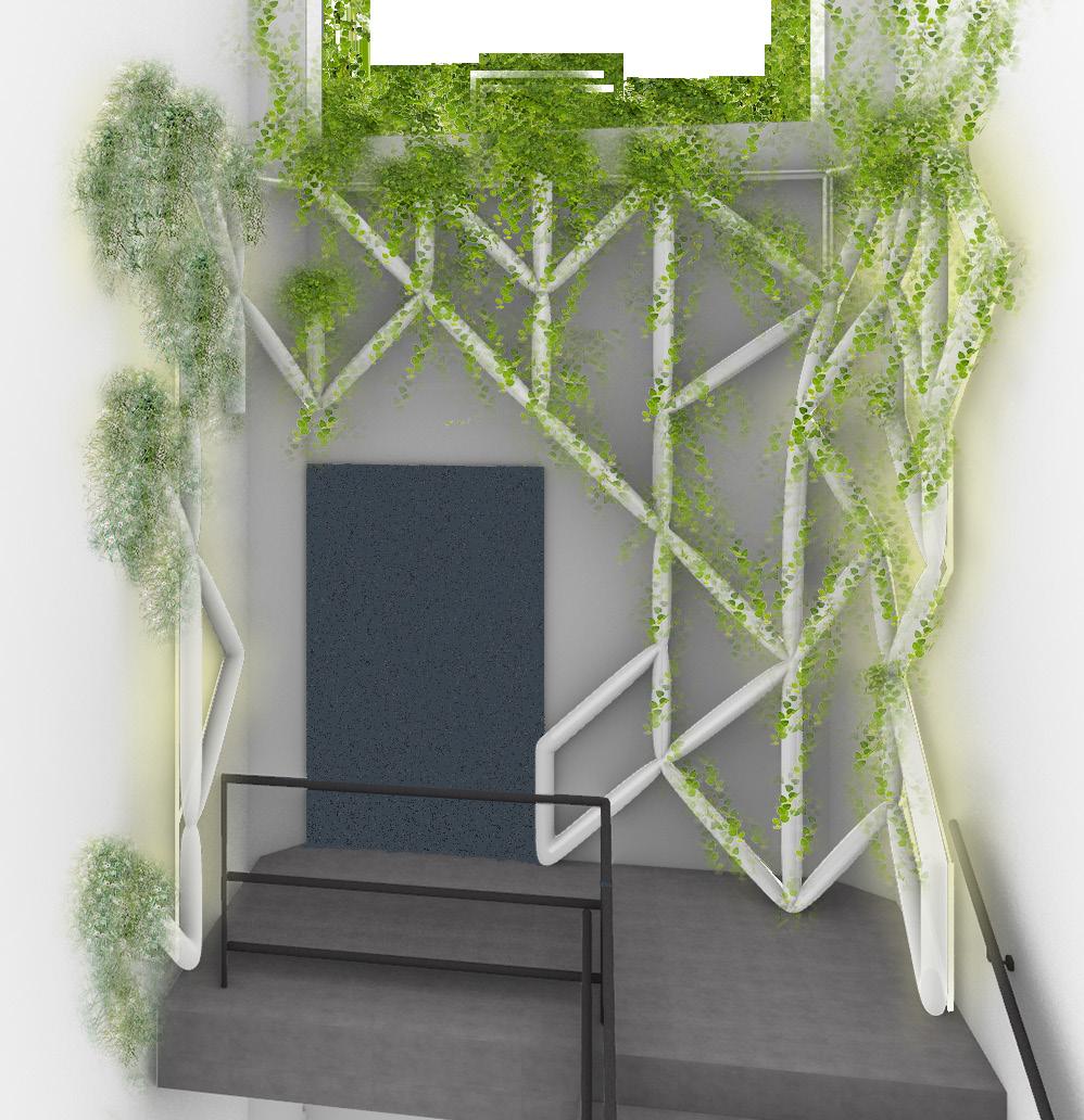
IMAGE:
New systems with added lighting and water plumbing. Relies on operable windows for ventilation
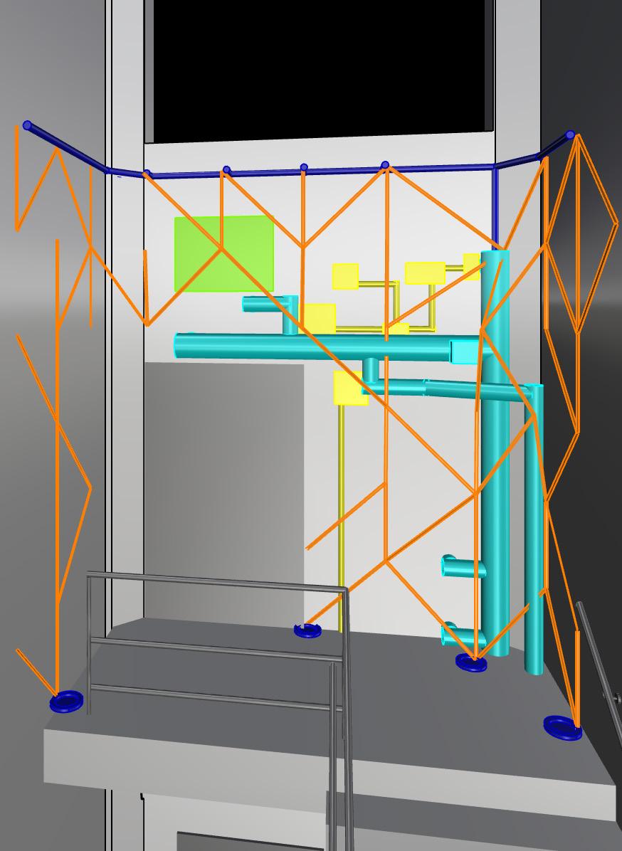
IMAGE:
Natural solution option with new windows on the eastern and western walls. New solar exposure simulation
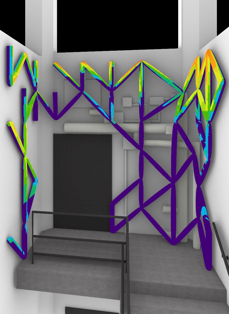
IMAGE:
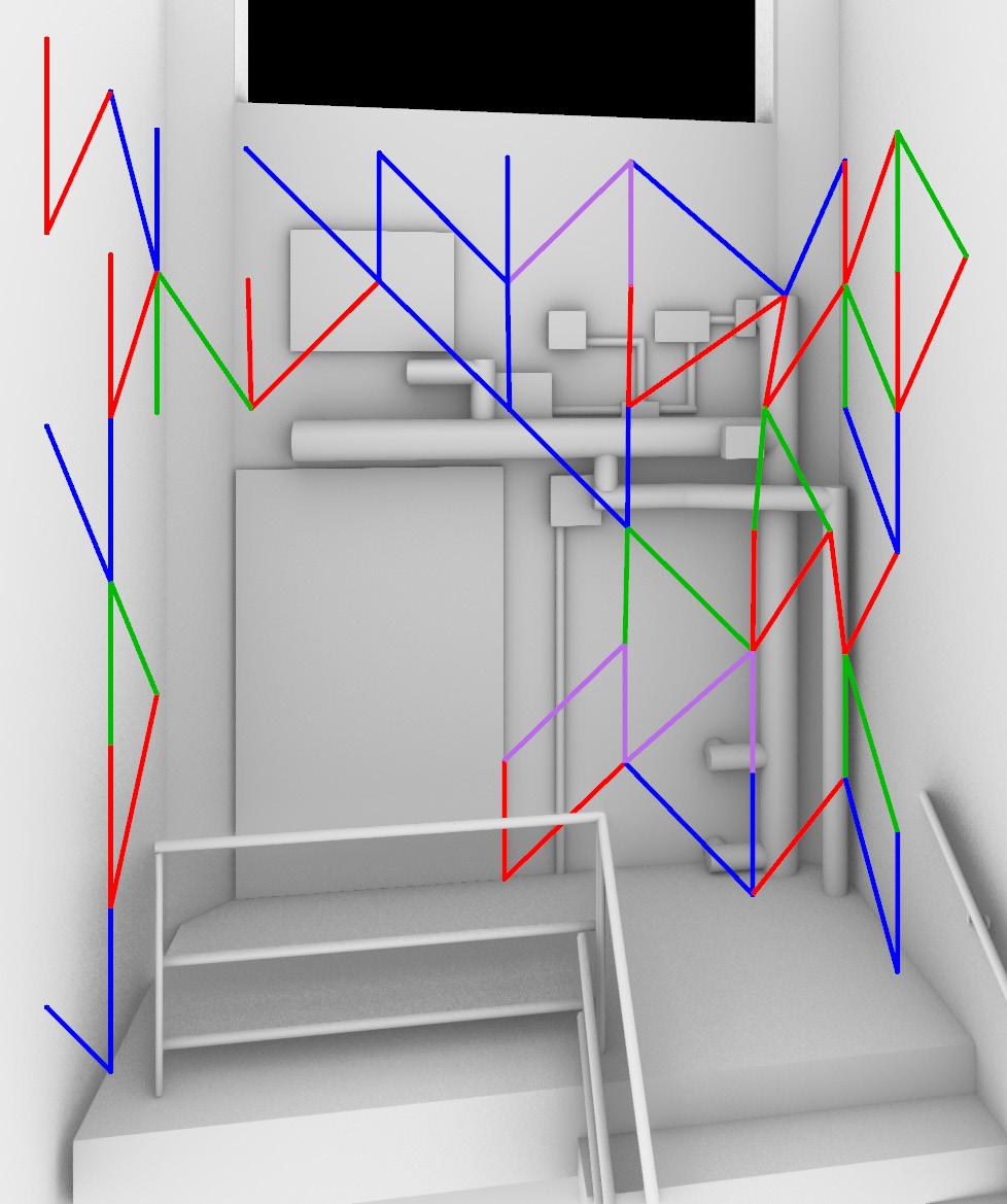
Top: 6 main joints isolated
Bottom: Exploded elevation with highlighted study area
DIGITAL MODELING
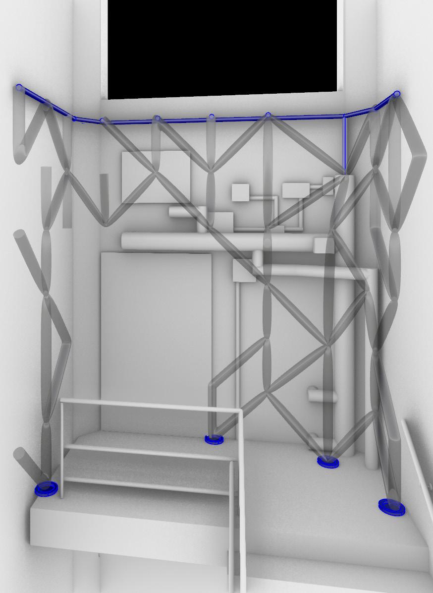
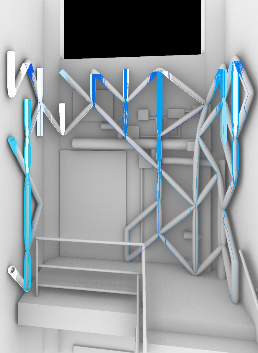
In the exploded elevation view of the scaffold, it is easy to divide the way in which the modules join into six main structures that repeat or very slightly modify themselves across the entire scaffold.
The bottom right hand side of the structure, highlighted in red, is the only place of a reasonable size for modeling that showcases all six joint structures.

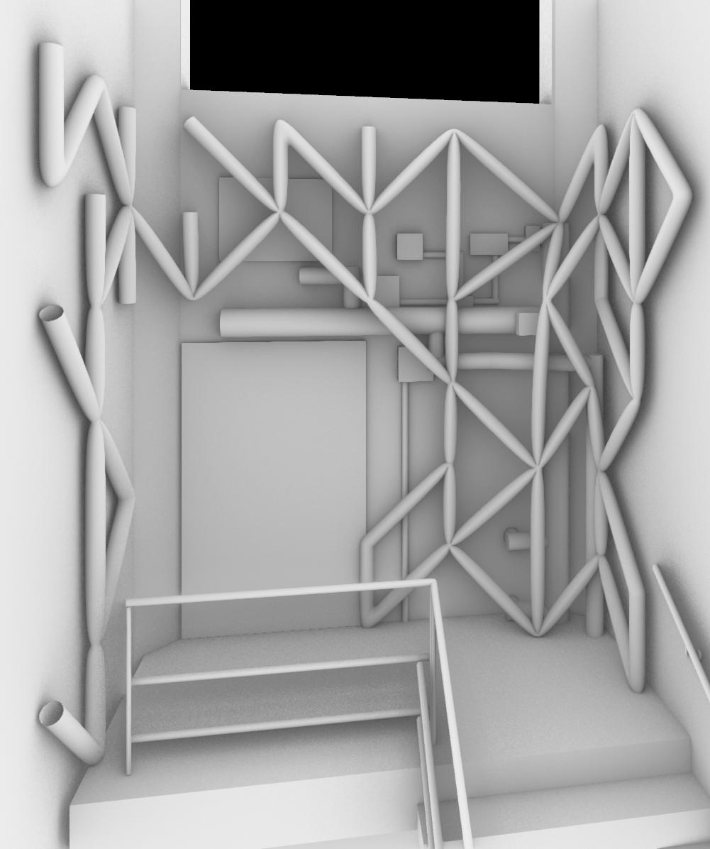
IMAGE: 3D view of the study area
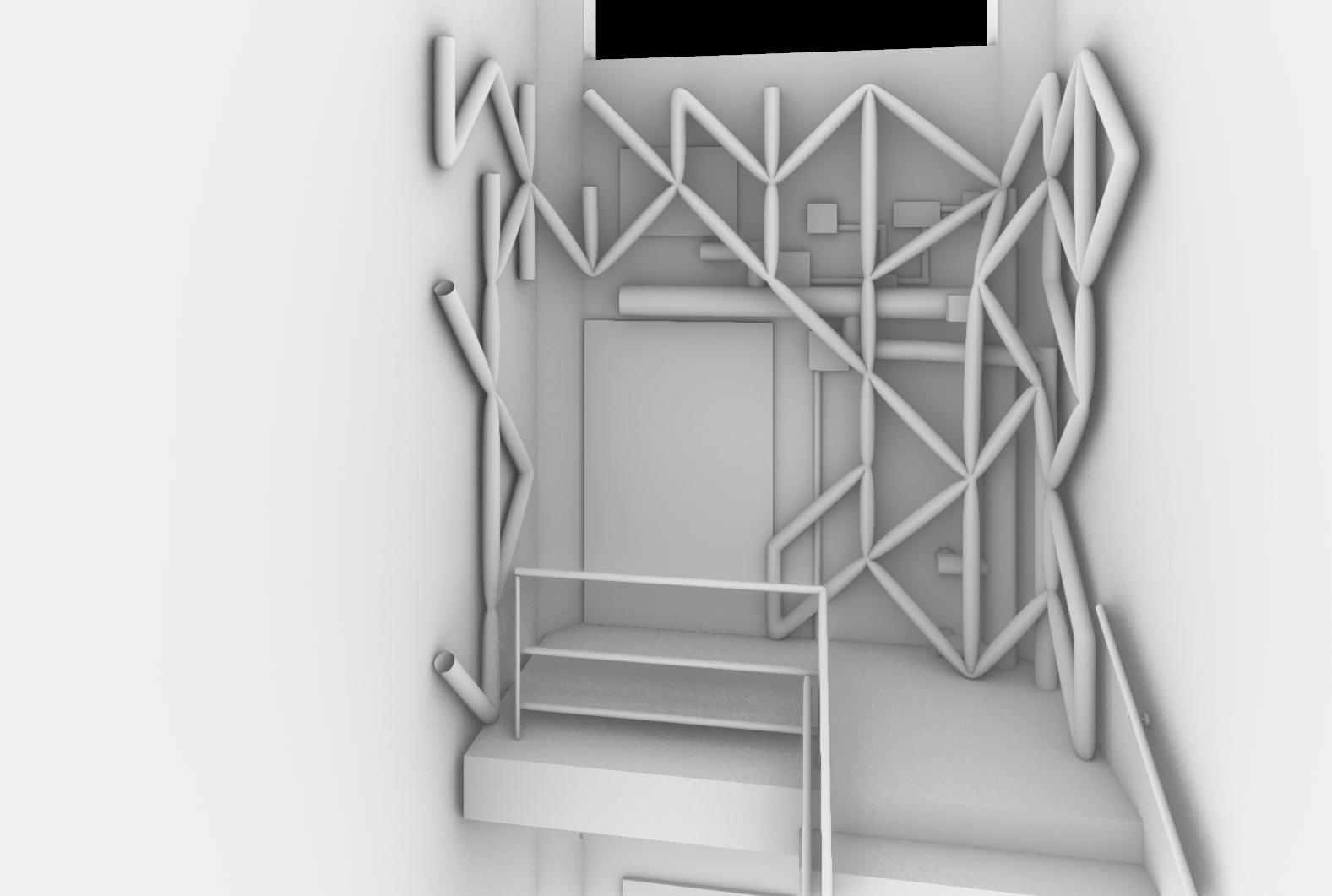
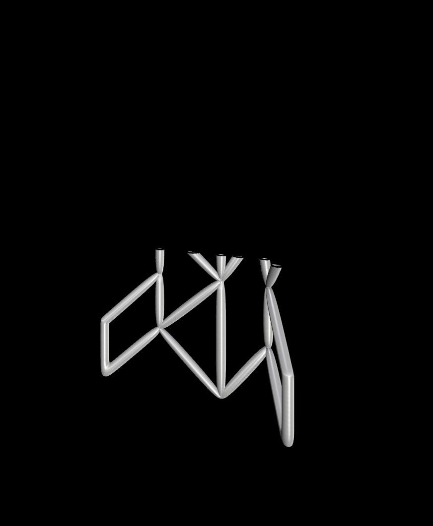
IMAGE:
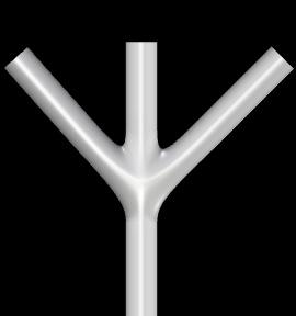
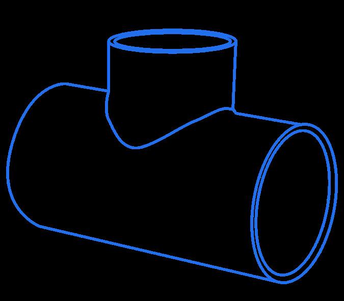
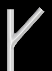
Top: Custom joints and PVC assembly plan
Mid: Off the shelf fitting symbols
Bottom: Actual PVC fitting geometry
PHYSICAL MODELING
It would require too much time and customization to build this scaffold exactly as it is modeled. Therefore, it is the best course of action to approximate the model with pre-made PVC pipe and fittings that mimic the geometry of the ideal scaffold while being infinitely more convenient and affordable. On this left most page, the process of abstracting the ideal joints into three PVC fittings that can be easily purchased at the hardware store is shown.
The designed diameter of this tubing system is four inches. However, in order to save on costs for this model, three-quarter inch pipe was used so that the structure could be analyzed and judged while on a student budget.
The prototype model can be seen on the right side of this spread with the constructed joints and the corresponding fitting called out. These images show not only the construction, but the planting of the prototype which had mixed success as it is much too small to properly hold moisture.


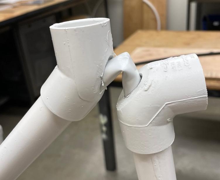
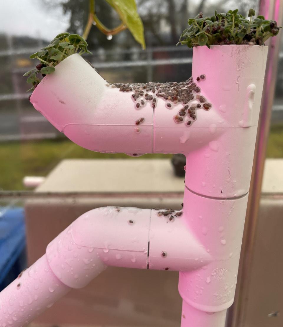
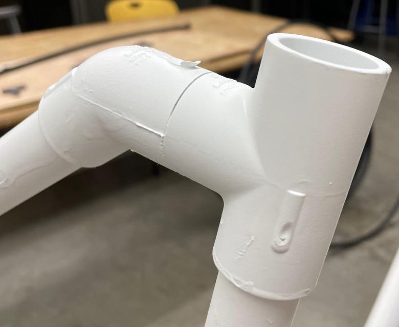
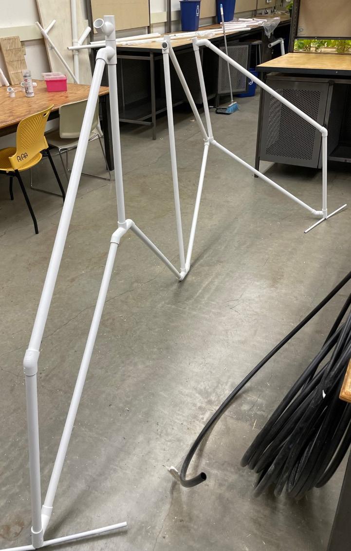
Left: Series of fabricated joints in model Right: Full scale model at reduced pipe diameter
TECHNICAL DRAWINGS
INTEGRATED DESIGN
The layers necessary for living systems are directly correlated to serving plant needs. Mainly, the light, water, and structure that supports plant growth. Developing these in detail is close to the final step for this design process and is documented here.
DETAILS
On the far right side of this spread, a close section of the installation system can be seen. This section details the wicking system, the pipes attachment to the wall, and the interaction of the roots within the pipes. Additionally, in the bottom right of this spread is a zoomed in diagram of all the layers and interactions present in each pipe.

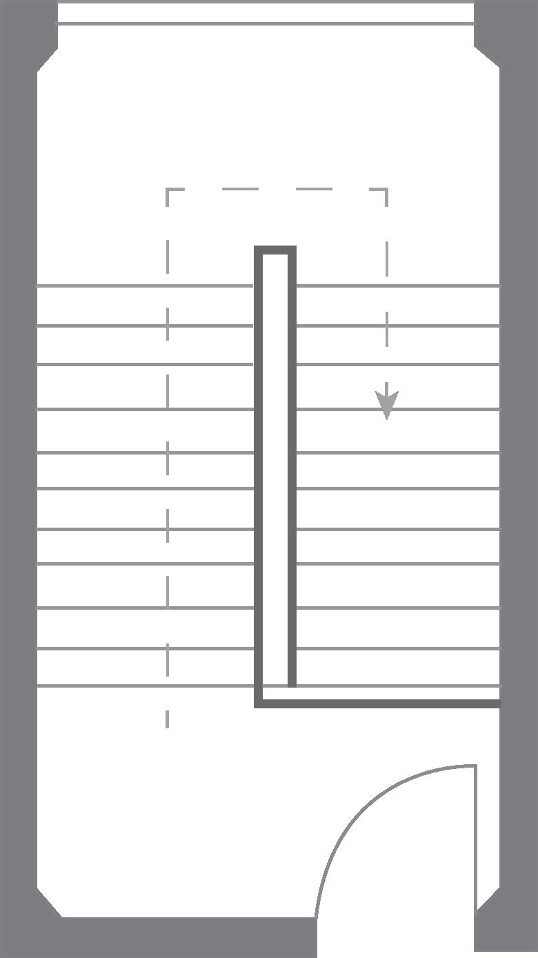
IMAGE:
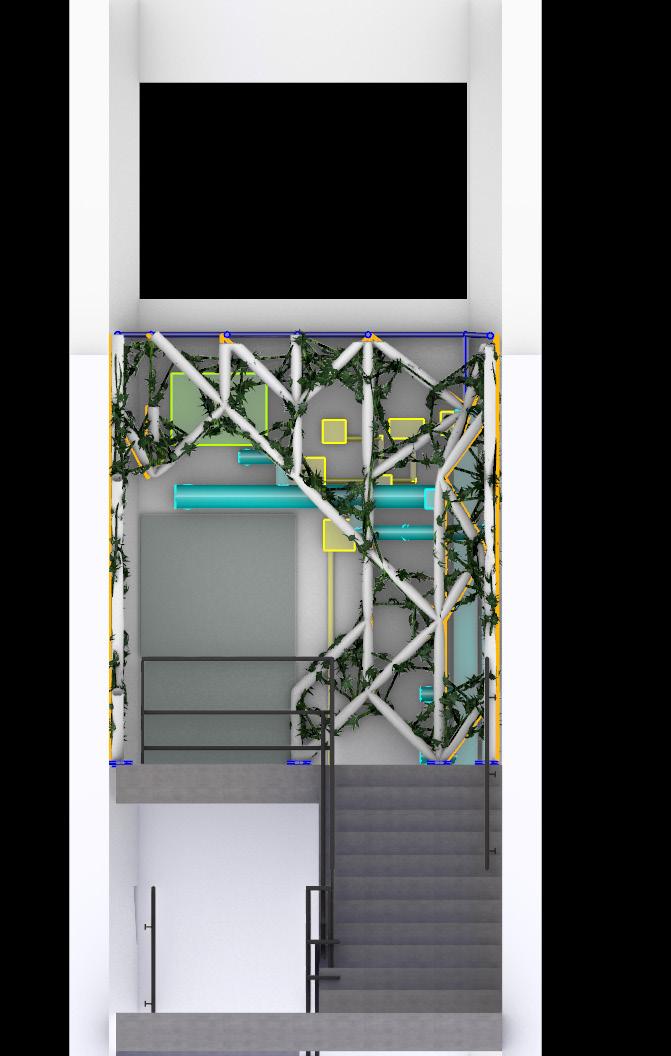
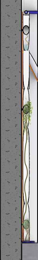
IMAGE:
Left: Elevation of final installation
Right: Detail section of eastern wall
Wicking intervention installation point
Pipe connection to wall, close up
Water help in pipes
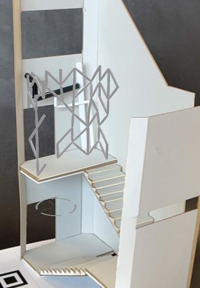
RENDER AND VR
FINAL RENDER
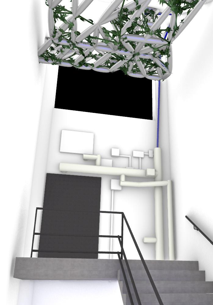
This displays the finalized concept of an activated landing on the fourth floor of the northern Lawrence stairwell. The new lighting system adds a soft and pleasing glow through the leaves of the trellising climbing fig and the waterfall effect of the Hoya on the left takes advantage of the side of the landing that does not require a path of egress.
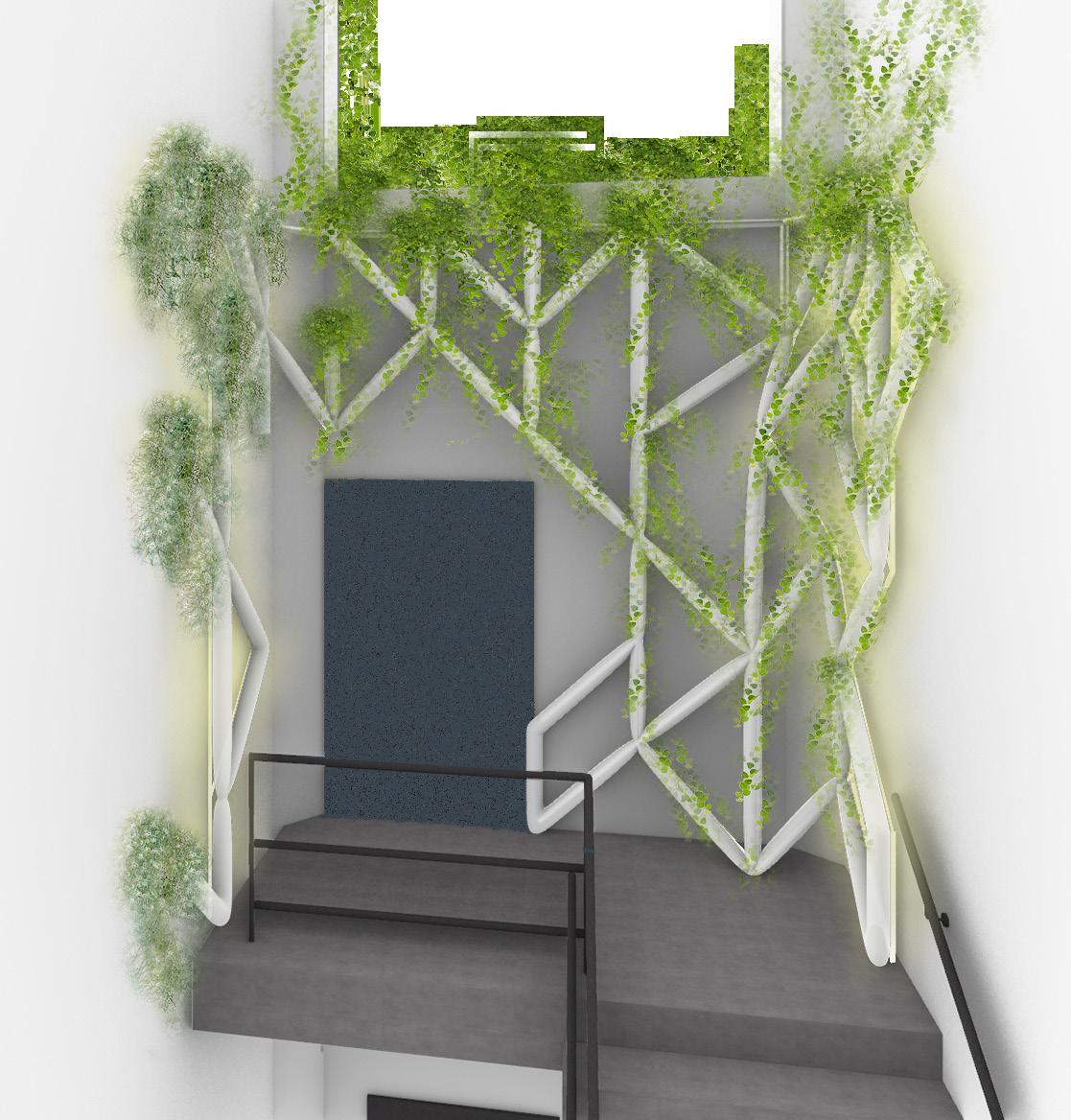
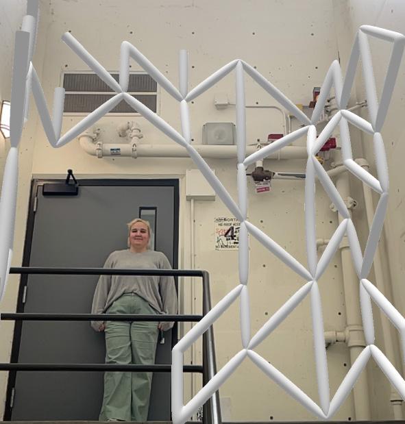
IMAGE:
VR image of full scale model in space
INSTALLATION OPTIONS
My base module is two feet tall which allows for an almost perfect bench seat. If this installation could be tapped into the plumbing systems in the wall, the piping system could drain back into the plumbing system at the base of the installation. Since the leg supports are full modular, the bench can be as long as needed to fit whatever space is desired.
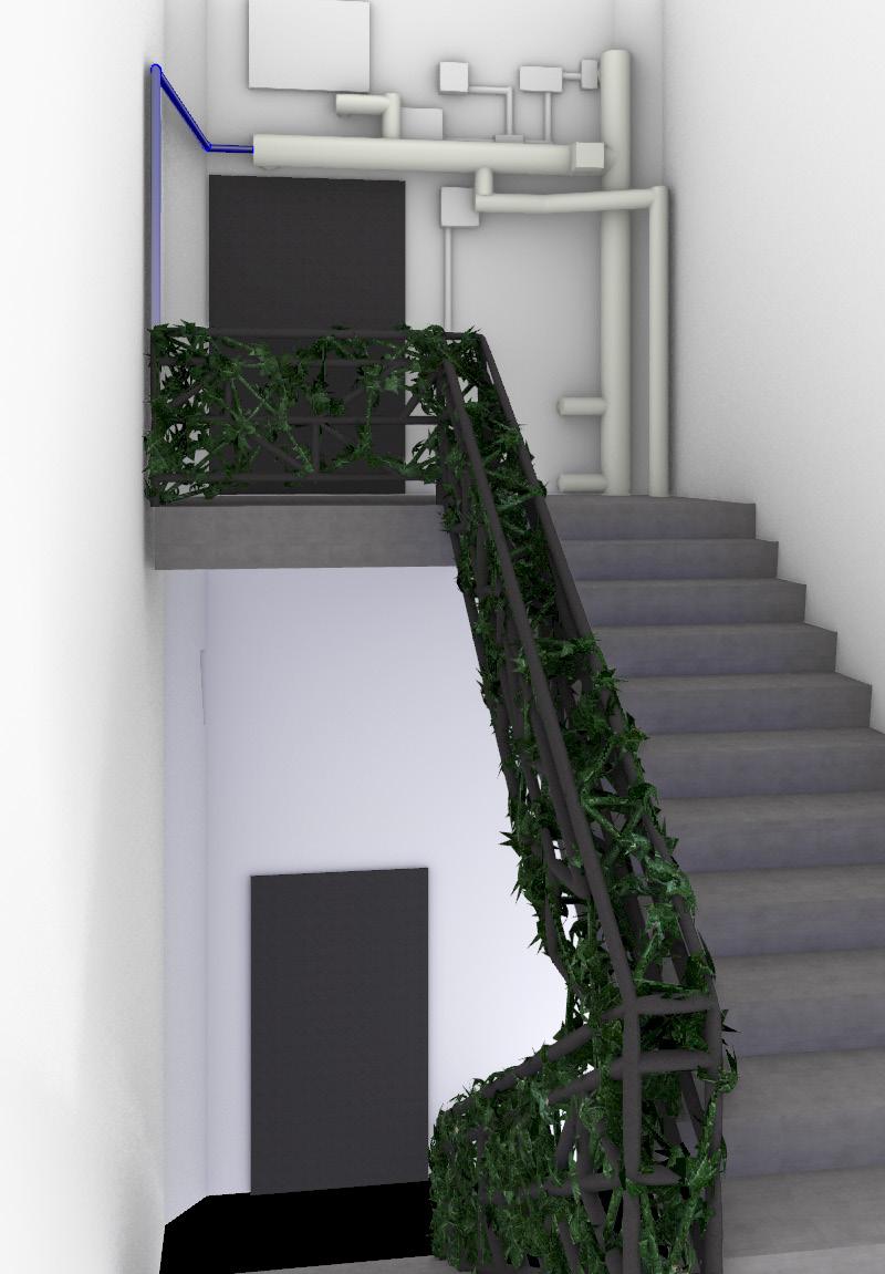
Scaling down the module size, I developed the triangular system into a hanging sculptural element in the stairwell. This design would require a change in material of the stairs to a more permeable surface that would allow drainage underneath the steps.
A triangular module can very easily be transferred to a parallelogram and thus fits perfectly into a railing system. This system utilizes several layers and varied module heights to allow the top railings to remain fully functional.
TWO TRIANGULAR MODULES STACKED
DRAINAGE OPPORTUNITY THROUGH BASE OF STRUCTURAL PIPE.
IMAGE:
Left: Ceiling install
Right: Railing install
VARIED MODULE HEIGHTS ALLOW FOR CONTINUED ACCESS TO RAIL (0.5’-1’-1’-0.5’)
BASE AND ITERATIONS
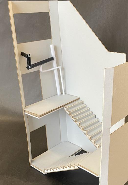
IMAGE:
Left: Existing space modeled at 1/2”-1’
Right: Module patterning in string
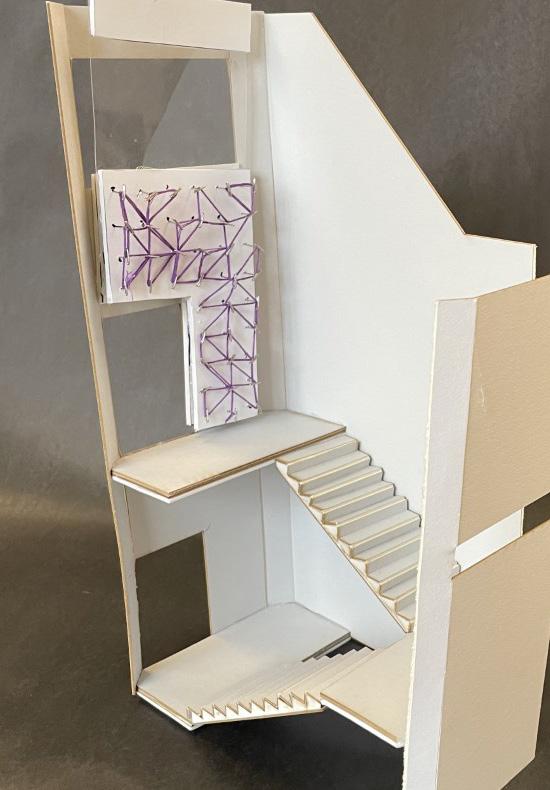
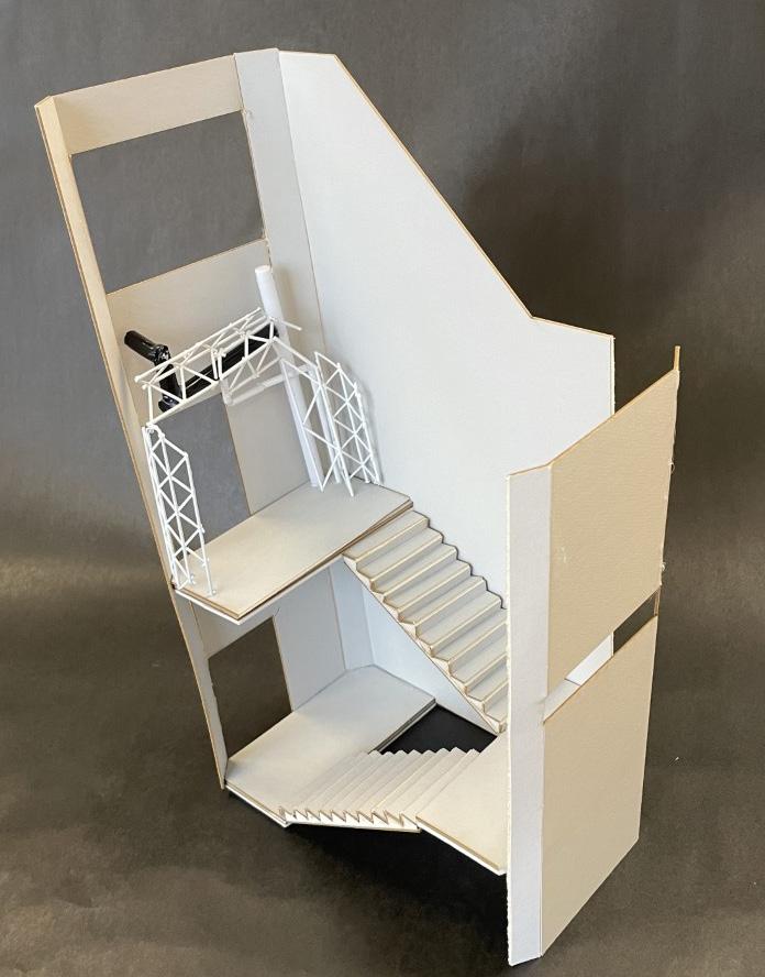
IMAGE:
Left: Physical model of module structure
Right: VR mapped to small model
GOING FURTHER
Throughout the course of this term I have learned about several new technologies and applications that have changed the way I approach design and especially interior systems. I really appreciated the way the scales of this project allowed me to examine my designs in great detail and at full scale. I have a deep interest in holistic design from site to building to interior and this is the perfect intersection of all those aspects of design in a very comprehensive and approachable form.
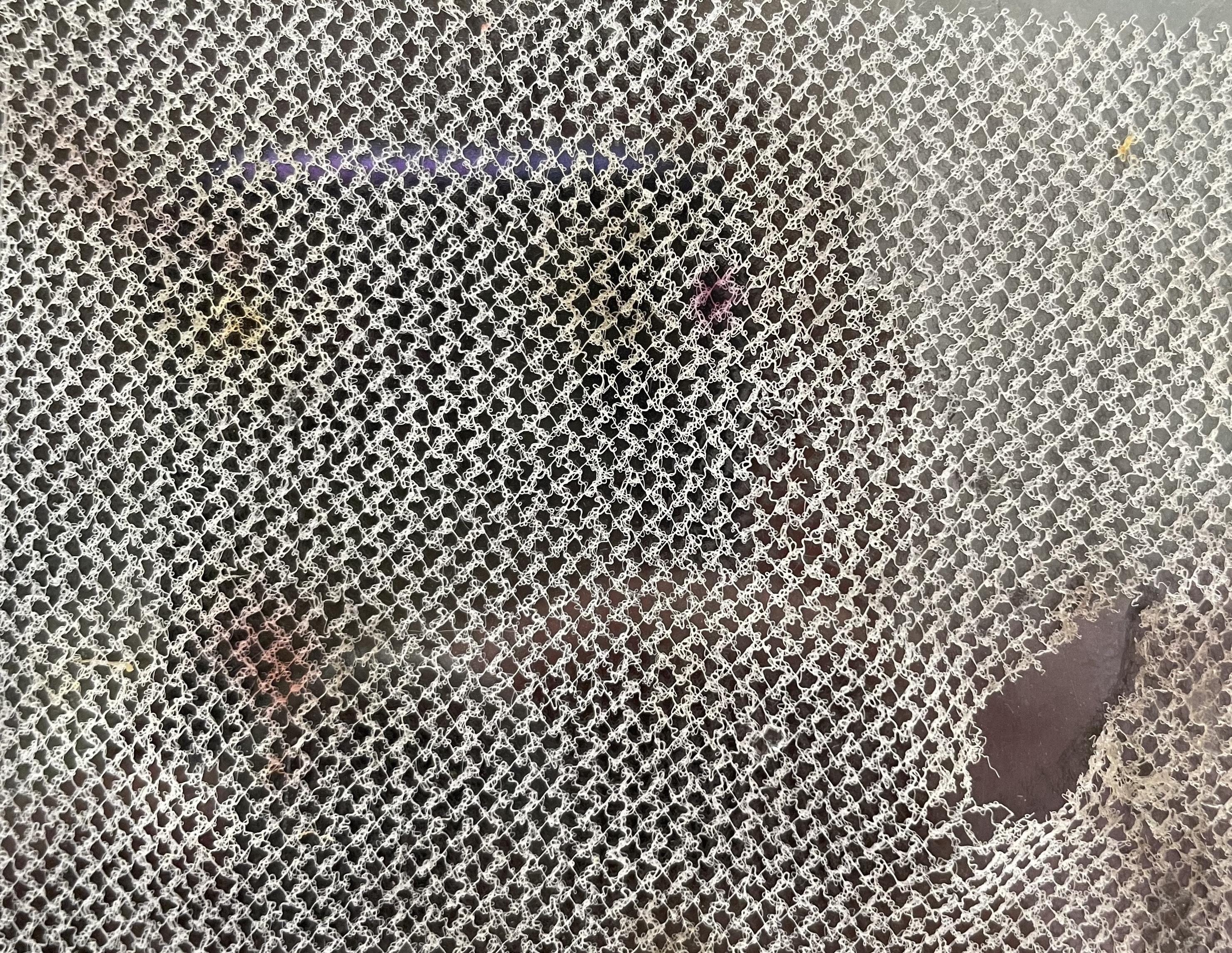
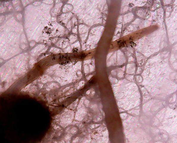
The new technologies presented in this term are where my curiosity peaked. To the right on this page, you can see the damage and evidence of occupation on my MEW scaffold after I carefully removed the sprouted seeds. Knowing how resilient and lasting these materials are will reflect their ability to be integrated into long term buildings. I want to continue to explore full scale building applications for MEW printing and see how it could be used on the exterior of the building to support vining plants closer to facade systems.
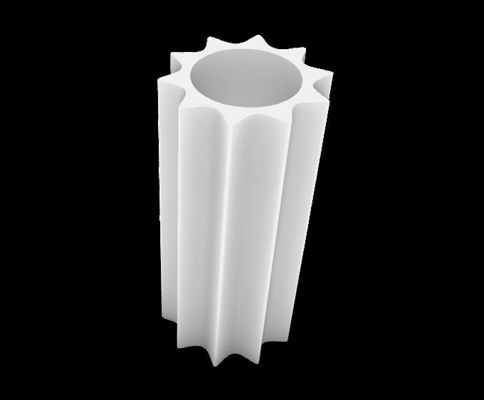
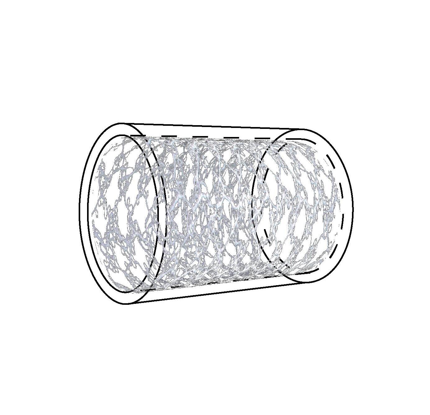
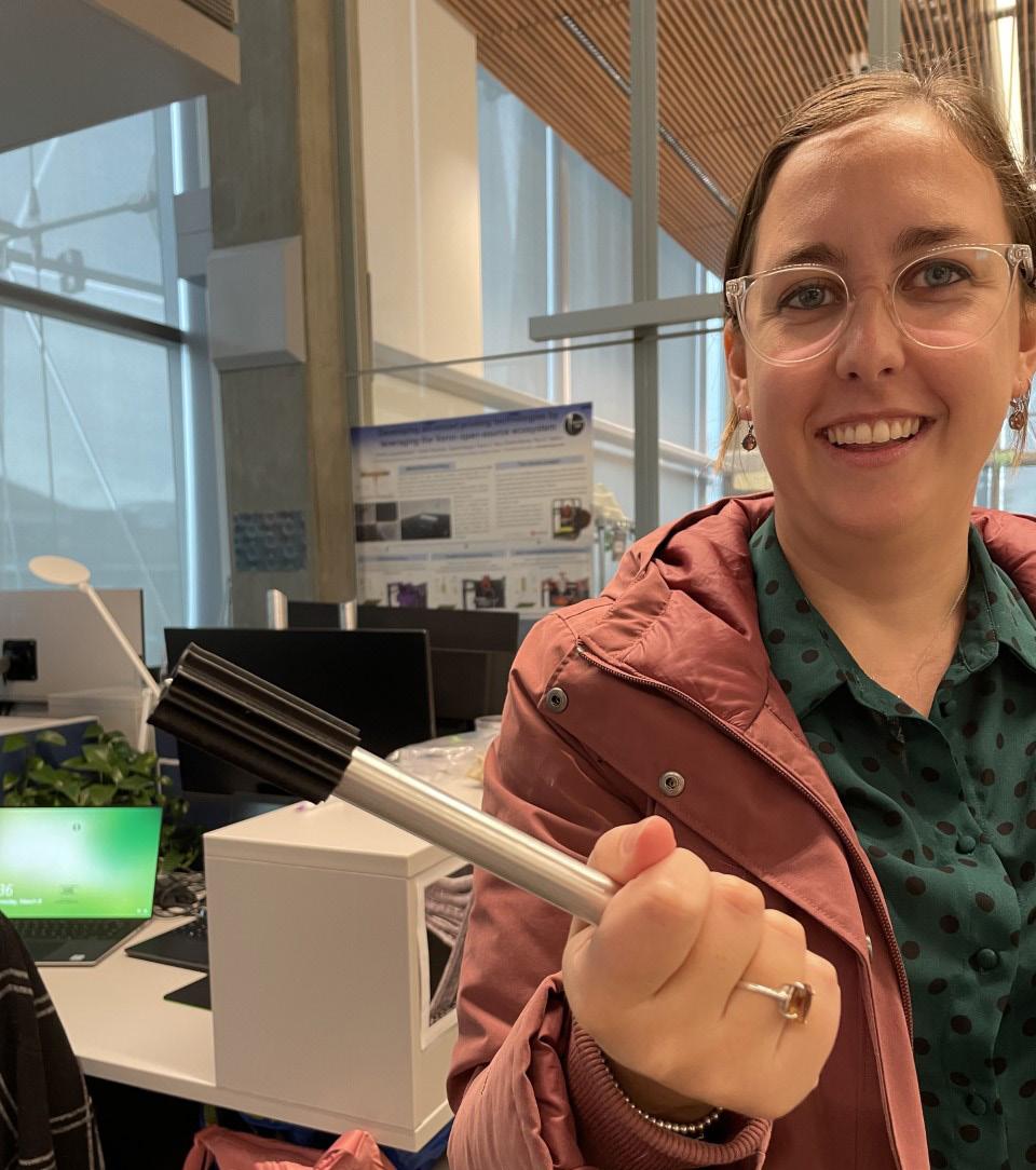
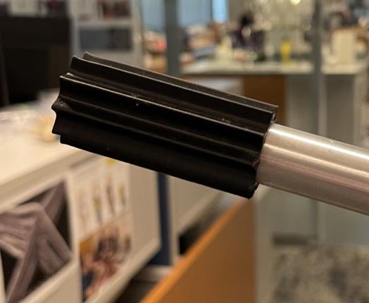
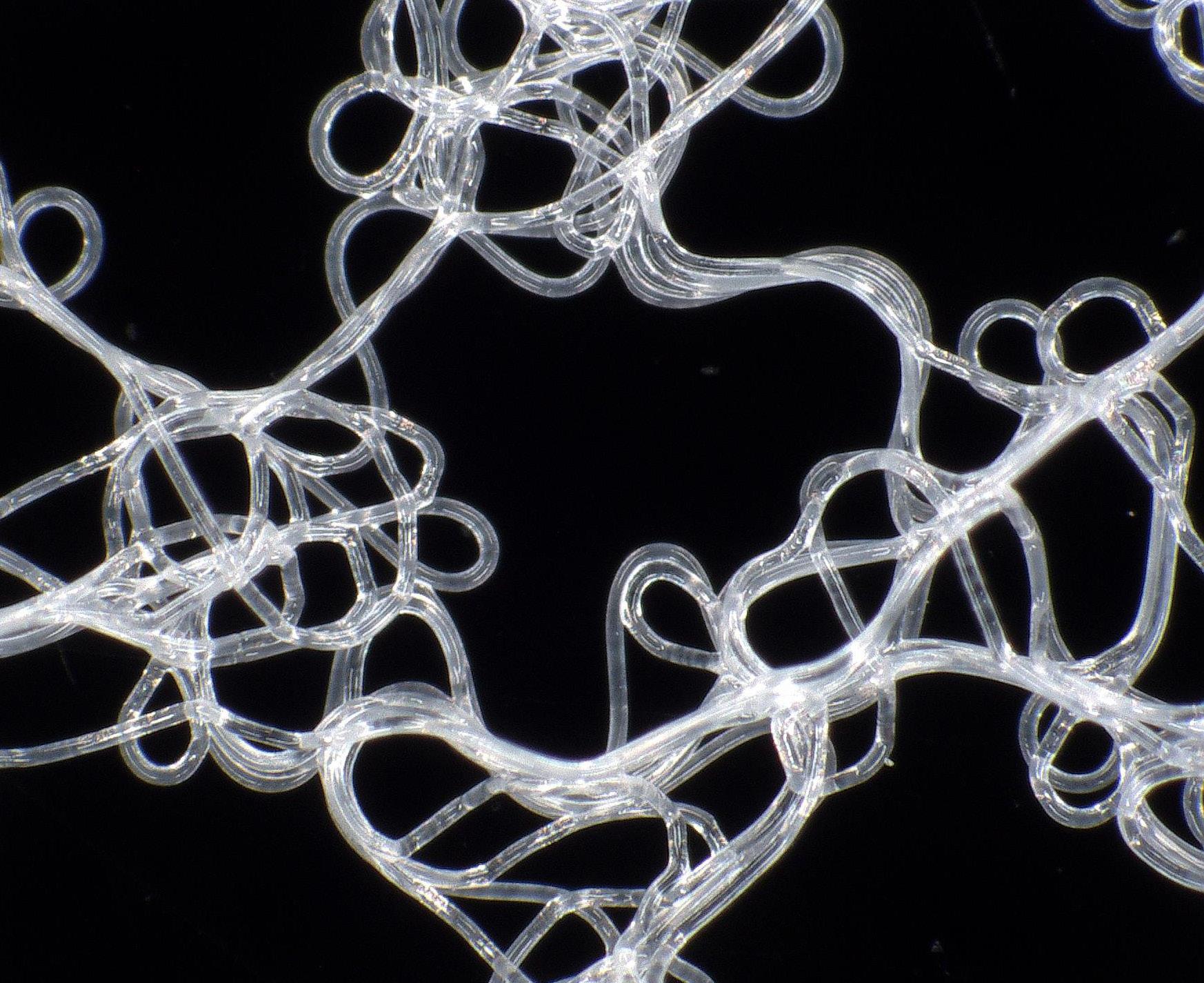
I have already begun to explore further applications and combinations of these technologies. Seen on the right page of this spread, are my beginning experiments testing the viability of the MEW scaffolds as a support for soil-less cultivation in these indoor systems. These test show a successful ability to wick and hold water (and nutrient). I plan to continue these experiments further next term and play with space filling designs and root compatibility. The first of these space filling designs can be seen on the far right of this spread. By MEW printing onto a mandrill of variegated radius, the resulting scaffold can be more efficiently folded into the PVC pipe and more closely mimic the natural aggregate of soil.
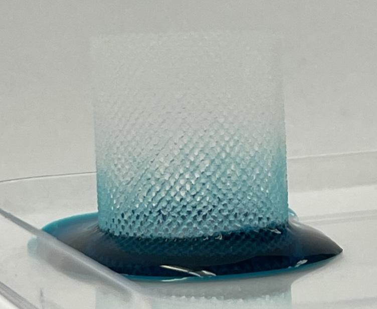
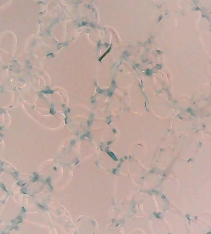
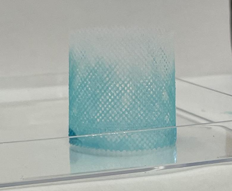
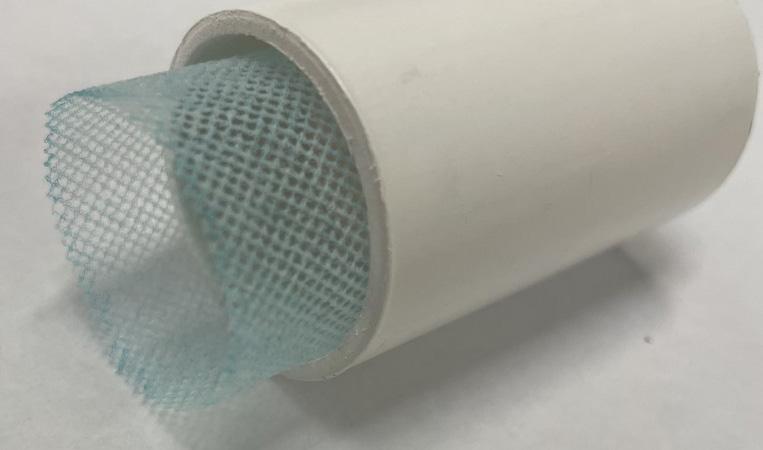
Explorations in wicking and space filling mandrills in MEW printing