
POMPIDOU 2
ARCH 484 | POLITES, MARY | WINTER 2023
HIELY HUYNH

HIELY HUYNH
About Me
EDUCATION
Bachelor of Architecture, Spring 2024
University of Oregon
INTERESTS
> multidisciplinary design
> graphic design
> industrial design
> sustainability
My name is Hiely and I’m a fourth year studying Architecture at the University of Oregon. I believe design can help us create a better tomorrow. The word ‘design’ covers a broad range of specialties and they can each provide a different perspective for a solution. Through my education at the University of Oregon, I have completed various multidisciplinary studios for my architecture degree and in this studio we worked in collaboration with the Phil and Penny Knight Campus for Accelerating Scientific Impact.
I came to the University of Oregon with an interest in sustainability and a desire to see how architecture can be designed to lessen our environmental impacts. However, my education here led me to see how architecture isn’t the only design field that can address the on going issues with the environment. My
selection of studios for my degree led to my interest in a multidisciplinary design approach and exploring various design fields such as brand design, industrial design, graphic design, and much more. Additionally, I enjoyed taking design build studios, such as furniture design, as I got the opportunity to bring my designs to life and experience them in front of my eyes.
After graduation, I would like to work with others in different design fields and bring my perspective and experience to the table as an Asian-American woman with a background in architecture. I am particularly interested in design fields that would either allow me to have a hands-on experience in building designs or allow me to explore my interests in creating graphics.
It is more than just building and making things
pretty to me. Design allows us to be creative in providing solutions for others. While the prettiest design is appealing, the goal is to convey our ideas to others so they can understand our vision.
IMAGE: Hiely (pictured right)
BACKGROUND
In the architectural climate of the Anthropocene, there is an increasing demand for the design of living systems (plants) in our built environment. Many factors drive this desire, but notably those of human health impacts and a lack of connection to nature. Our strategies for integrating living systems need to be revised as they approach the relationship with plants just as they have been since its popularization during the Victorian Era. During this period, plants were brought indoors for our enjoyment, made possible from pots and containers. This vessel design continues in our current practices, despite the fact that we understand better the behavior and needs of plants today thanks to science and technology.
In this studio, we examined building systems with the aim to integrate them with living systems for indoor spaces. We questioned what systems we can expose, where they occupy our space, what species might be best accompanied by these systems, and how this can impact and change the use of our built environment. The outcome of this studio proposed designs for interior architectural applications that integrate living systems.
This studio designed concepts with 3D models and developed physical prototypes through digital fabrication. We started with a relatively new 3D printing method called melt electrowriting that is used for biofabrication and moved to 1:1 at scale mock-ups to accommodate species and test their growth strategies on these models.
IMAGES:
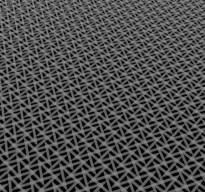
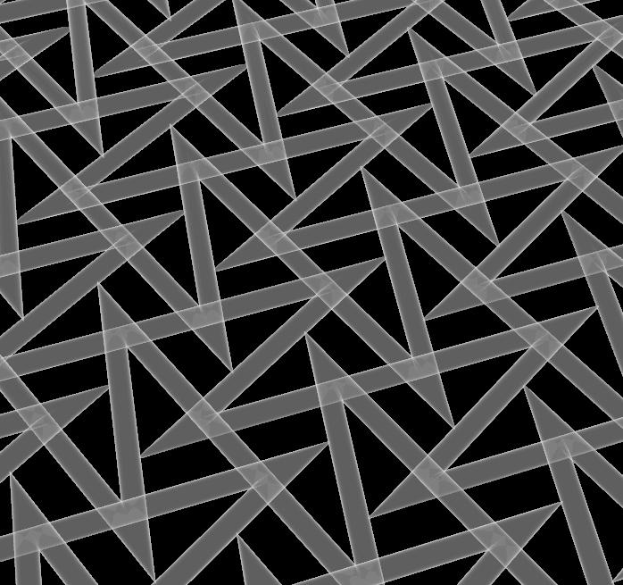
digital model of pattern 01 (left)
digital model of pattern 01 close-up (right)
PATTERN 01
MELT ELECTROWRITING SCAFFOLDS
This first pattern focused on the overlap between the rows to develop stronger structure.
The speed for this print was F600.
1 mm x 1 mm
IMAGES:
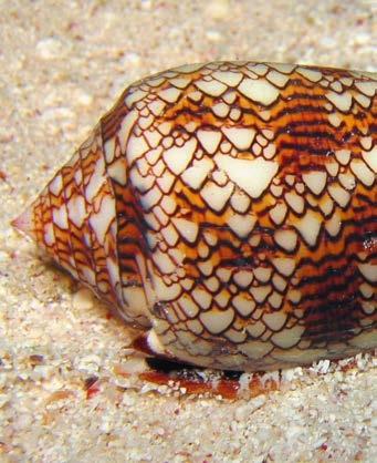
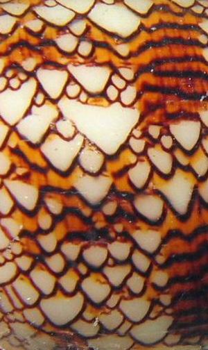
Gastropod Mollusc (top)
Gastropod Mollusc close-up (bottom)
IMAGES:
digital model of pattern 02 (left)
digital model of pattern 02 close-up (right)
PATTERN 02
MELT ELECTROWRITING SCAFFOLDS
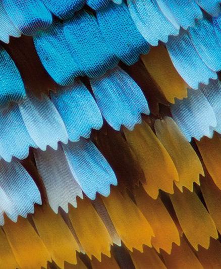
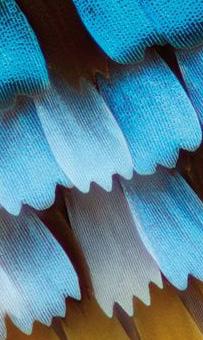
In this pattern the aim was to try to generate rows that are similar to scales. This lacked vertical connections.
The speed for this print was F600.


IMAGE:
Butterfly Wing Scales (top)
Butterfly Wing Scales close-up (bottom)
IMAGES:
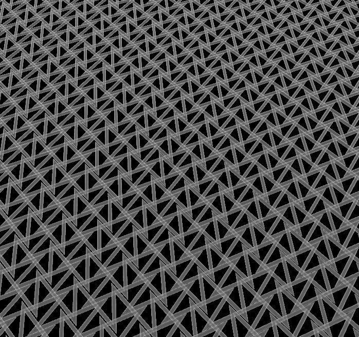
digital model of pattern 03 (left)
digital model of pattern 03 close-up (right)
PATTERN 03
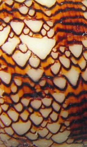
This pattern generation was more focused on mimicking the shell while keeping overlaps.
The speed for this print was F600.
MELT ELECTROWRITING SCAFFOLDS 1 mm x 1 mm

IMAGES:
Gastropod Mollusc (top)
Gastropod Mollusc close-up (bottom)

IMAGES:
digital model of pattern 04 (left)
digital model of pattern 04 close-up (right)
PATTERN 04
This pattern looks at the voids between the coral and the geometric lines created.
The speed for this print was F600.
MELT ELECTROWRITING SCAFFOLDS 1

IMAGE:
Coral (top)

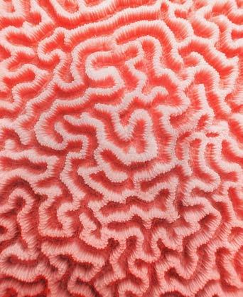

Coral close-up (bottom)
IMAGES:
digital model of pattern 05 (left)
digital model of pattern 05 close-up (right)
PATTERN 05
MELT ELECTROWRITING SCAFFOLDS
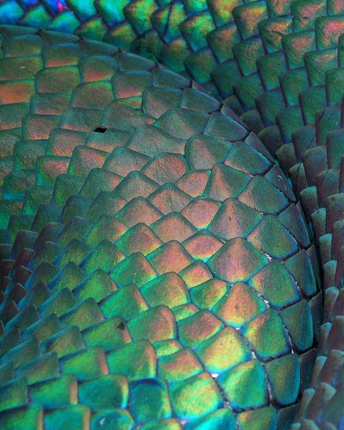
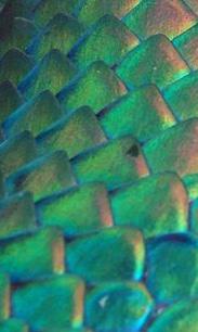
In this pattern the aim was to try to generate small triangular units.
The speed for this print was F400.

1 mm x 1 mm

IMAGE:
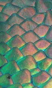
Snake Scales (top)
Snake Scales close-up (bottom)
IMAGES:
digital model of pattern 06 (left)
digital model of pattern 06 close-up (right)
PATTERN 06
MELT ELECTROWRITING SCAFFOLDS
This pattern is more chaotic and close together. The slower print speed makes it more squiggly and wavy.
The speed for this print was F100.


IMAGE:
Sand Dunes (top)
Sand Dunes close-up (bottom)


IMAGES:
digital model of pattern 07 (left)
digital model of pattern 07 close-up (right)
PATTERN 07
MELT ELECTROWRITING SCAFFOLDS
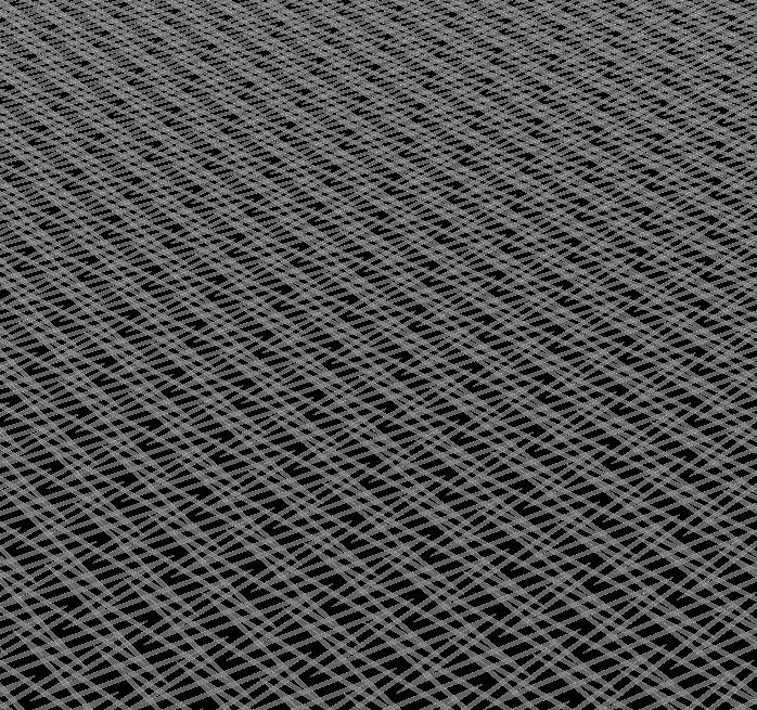
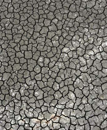
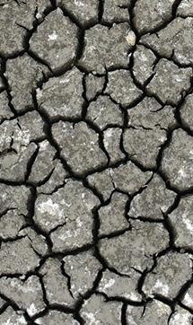
This pattern has small voids and units to mimic the drought cracks.
The speed for this print was F600.
1 mm x 1 mm

IMAGE:
Drought Cracks (top)
Drought Cracks close-up (bottom)
IMAGES:
digital model of pattern 08 (left)
digital model of pattern 08 close-up (right)
PATTERN 08
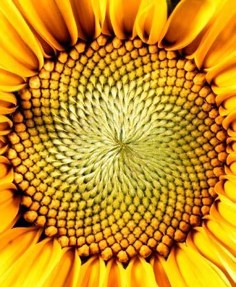
This pattern is rectangular and small which is similar to the seed head units.
The speed for this print was F600.
MELT ELECTROWRITING SCAFFOLDS 1 mm x


IMAGE:
Head of Sunflower (top)
Head of Sunflower (bottom)

IMAGES:
digital model of pattern 09 (left)
digital model of pattern 09 close-up (right)
PATTERN 09
In this pattern the aim was to try to generate more triangular units which are bigger. This is closer in similarity.
The speed for this print was F600.


IMAGE:
Snake Scales (top)
Snake Scales close-up (bottom)

TEST PRINTS
10X10 SCAFFOLDS
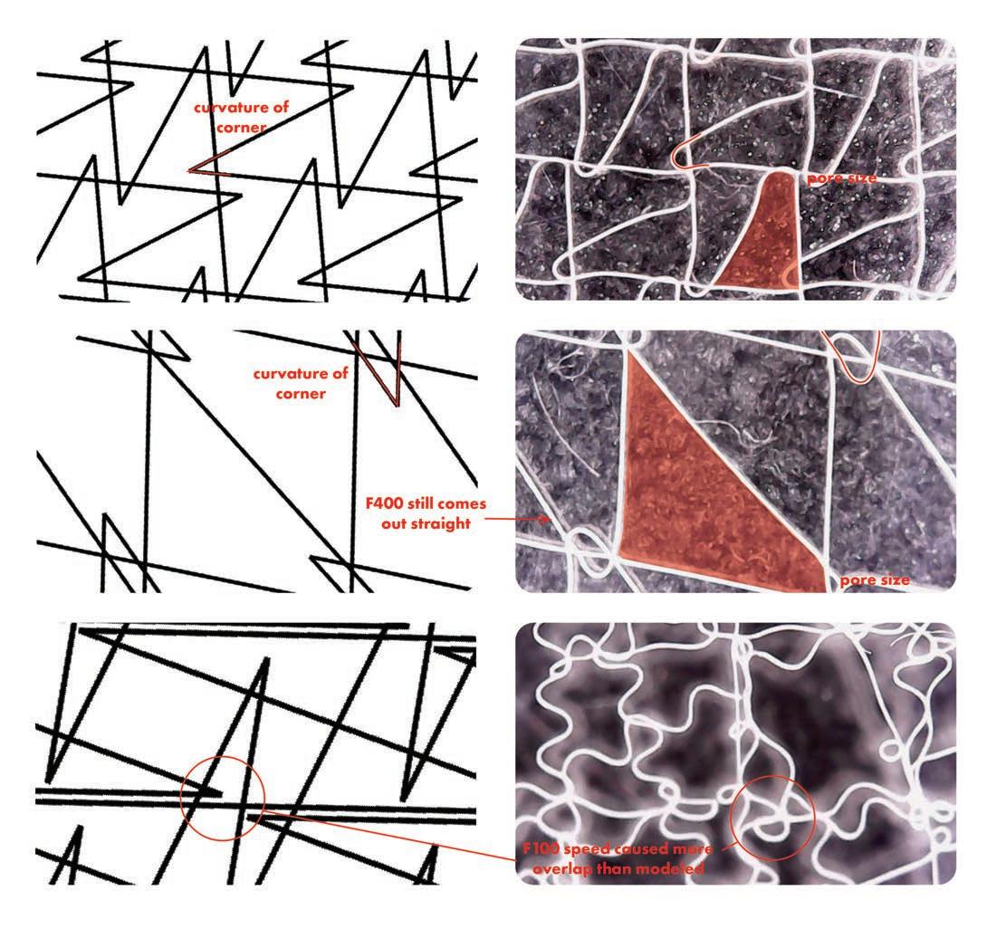
For the samples, I chose to print patterns 03, 05, and 06. All the 10mmx10mms chosen successfully printed. The digital versions came out quite similar to the physical version, expect for pattern 06. Pattern 06 was printed at F100 which would cause it to have quite a bit of random curvature. It caused more overlap than the digital version showed. Page 21 shows how ‘F’ speed affects the print.

FINAL PRINT
90X90 SCAFFOLD
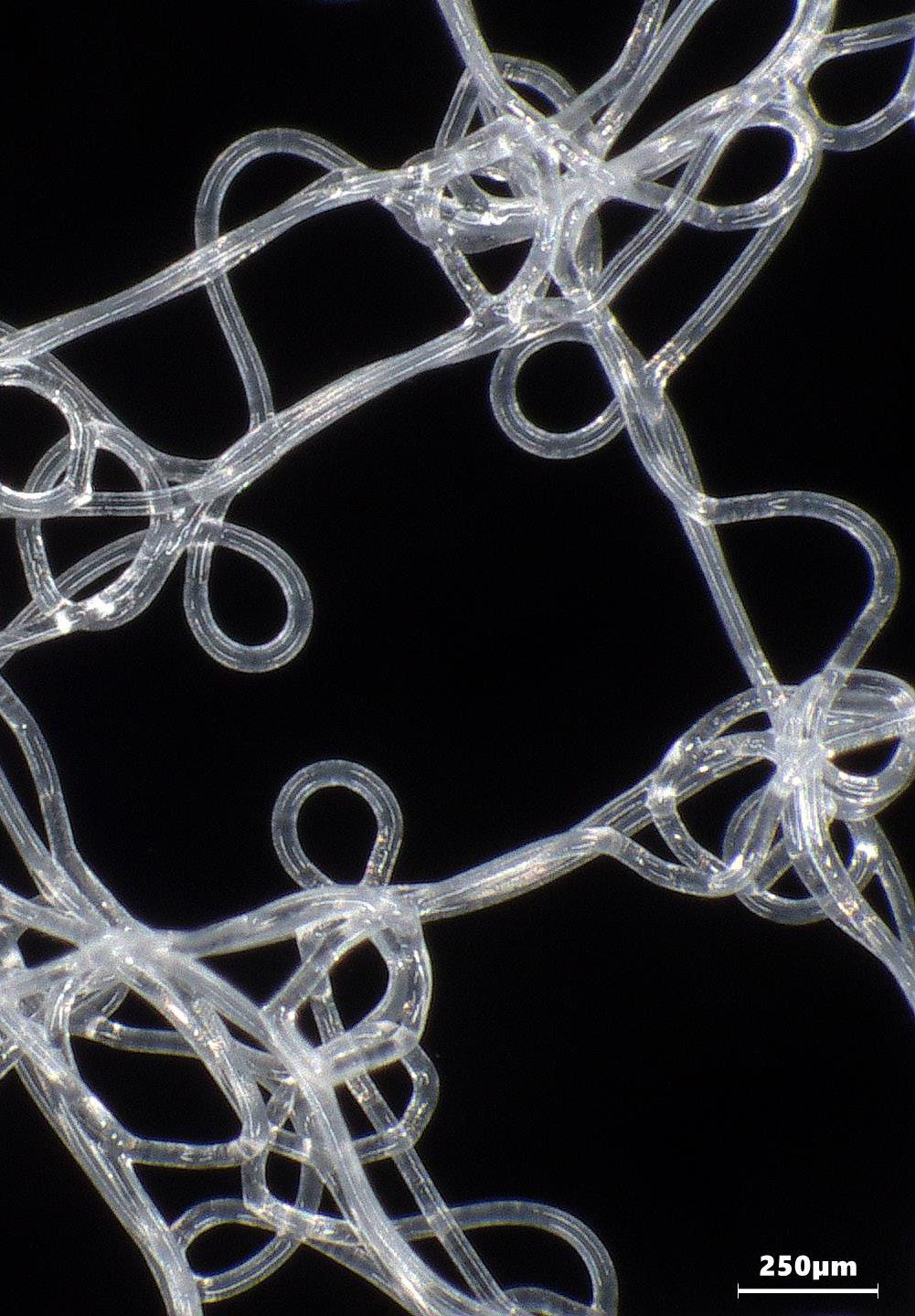
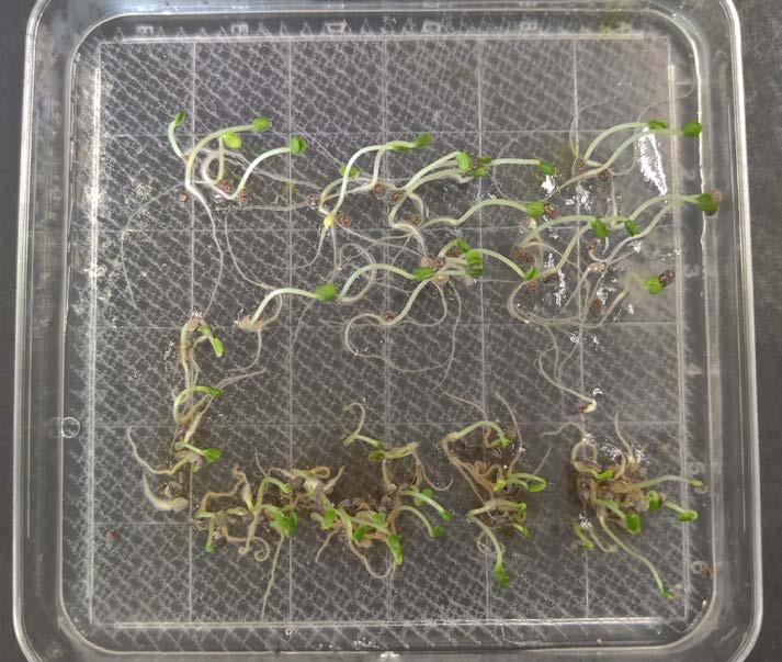
While all 3 patterns printed with no errors as a 10mmx10mm scaffold, it was not the same for a 90mmx90mm. Pattern 03 had overlap in the test print, but proved to be quite minimal. This may have caused it to fail when printing multiple layers for the 90mmx90mm. The fibers don’t necessarily want to stick to each other. Pattern 08 was the second choice for the final print and it may have had the same issue with overlap. It was not test printed, but the digital versions shows minimal overlap as well. I decided to go with pattern 06 which is coupled with sand dunes as the next choice since the test print proved to have quite a bit of overlap at speed F100 and the layering would help with the structure as well. It printed successfully as a 90mmx90mm scaffold.
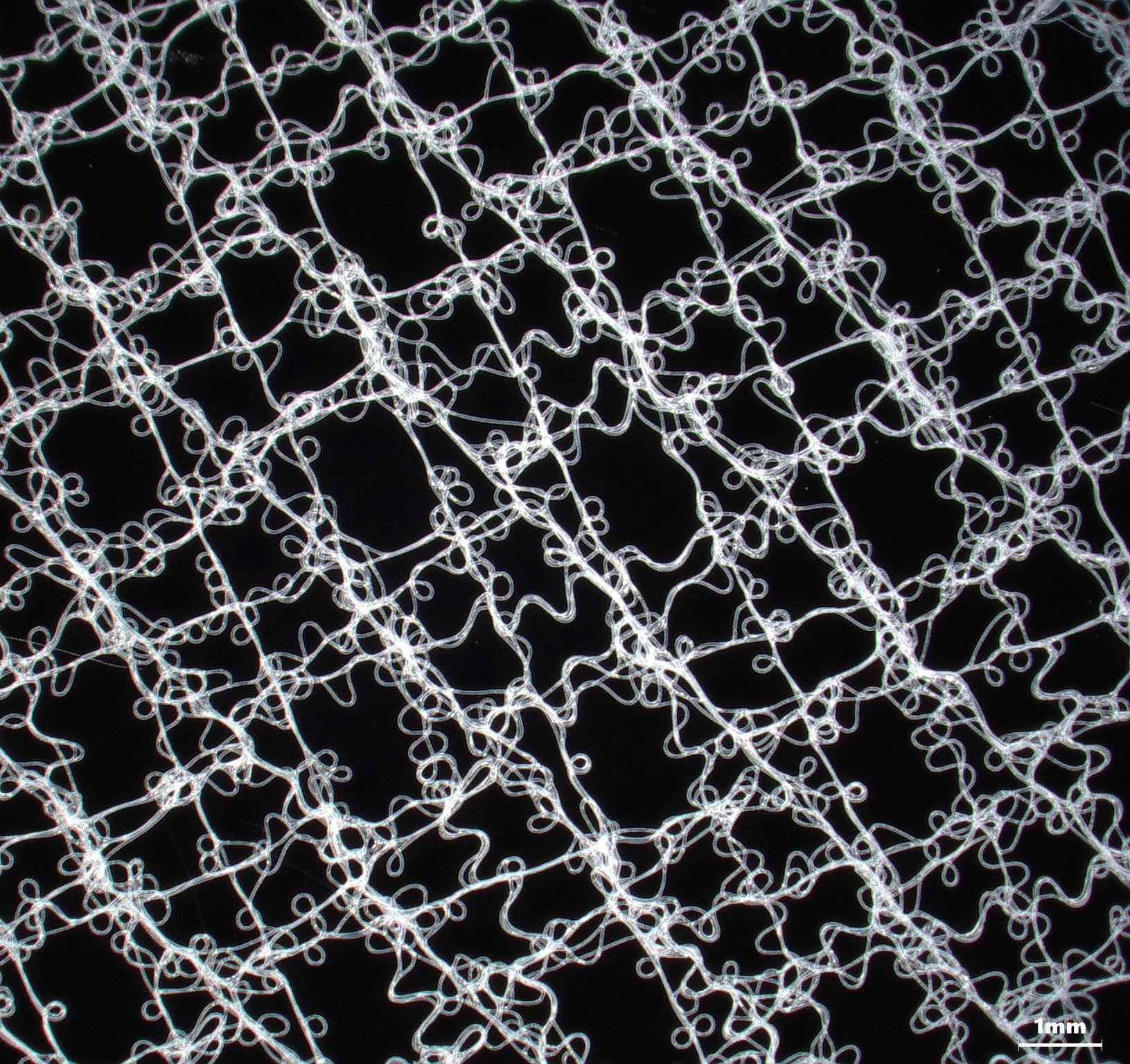
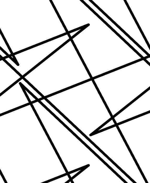
IMAGE:
pattern 06 digital linework (left) pattern 06 under the microscope (right)
IMAGES: 90mmx90mm scaffold with chia sprouts
PLANTING THE SCAFFOLD
SEEING HOW SEEDS WOULD INTERACT
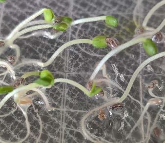
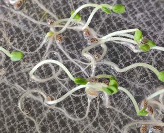
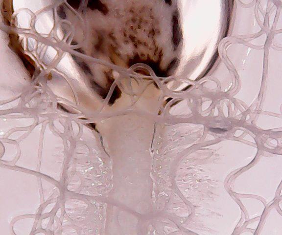
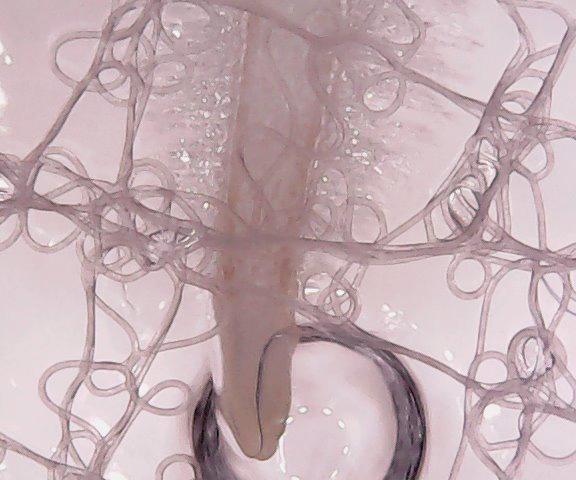
The 90mmx90mm scaffold was planted with chia seeds and had glezan as media. With the microscope, we can see how the seeds interact with the mesh.
IMAGES:
chia interacting with scaffold under microscope
COMPONENT SYSTEMS
CHOOSING A SPACE IN LAWRENCE
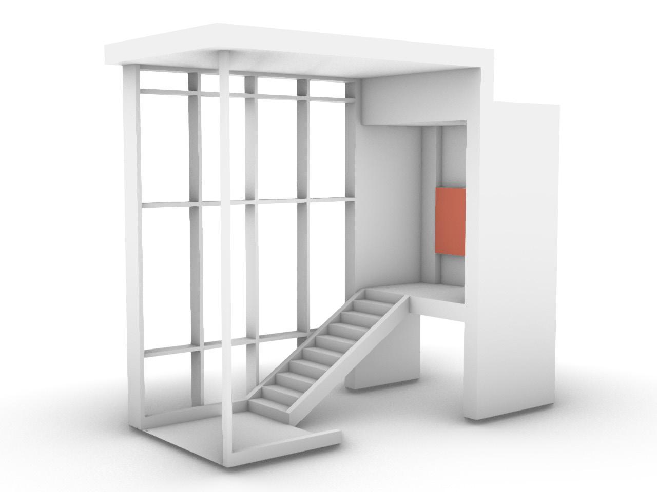
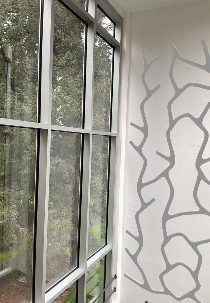
Moving on to the next phase, we were to choose an optimal space in Lawrence Hall to place the component systems we would design. I went with the isolated staircase on the most western side of the building. There is a double height space between the 2nd and 3rd floor.
EXISTING CONDITIONS
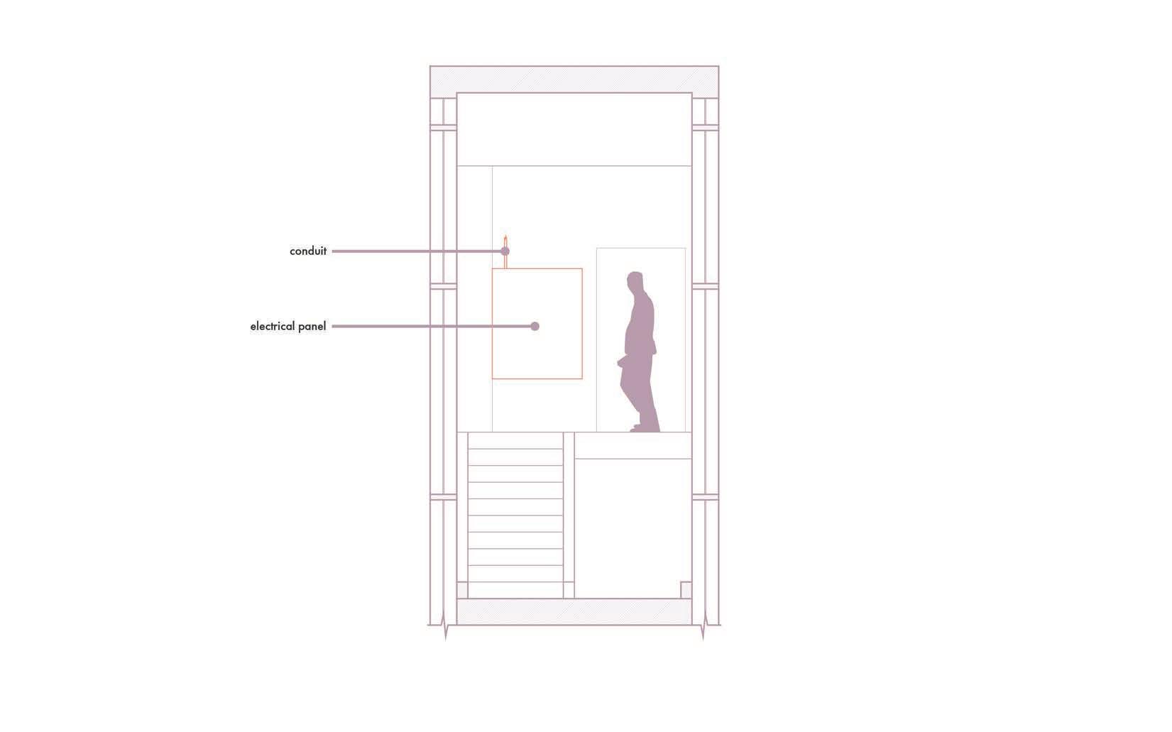
The space gets plenty of light from the north and south side as both sides of the staircase are fully glazed. Though there are no physical structures on either side, there are large trees nearby. Opposite of the wall chosen for the component systems is an electrical panel and some conduits.
See Second Floor North
IMAGE: floor plan of second floor of Lawrence Hall
IMAGES:
selected space (left)
opposite wall of selected space (right)
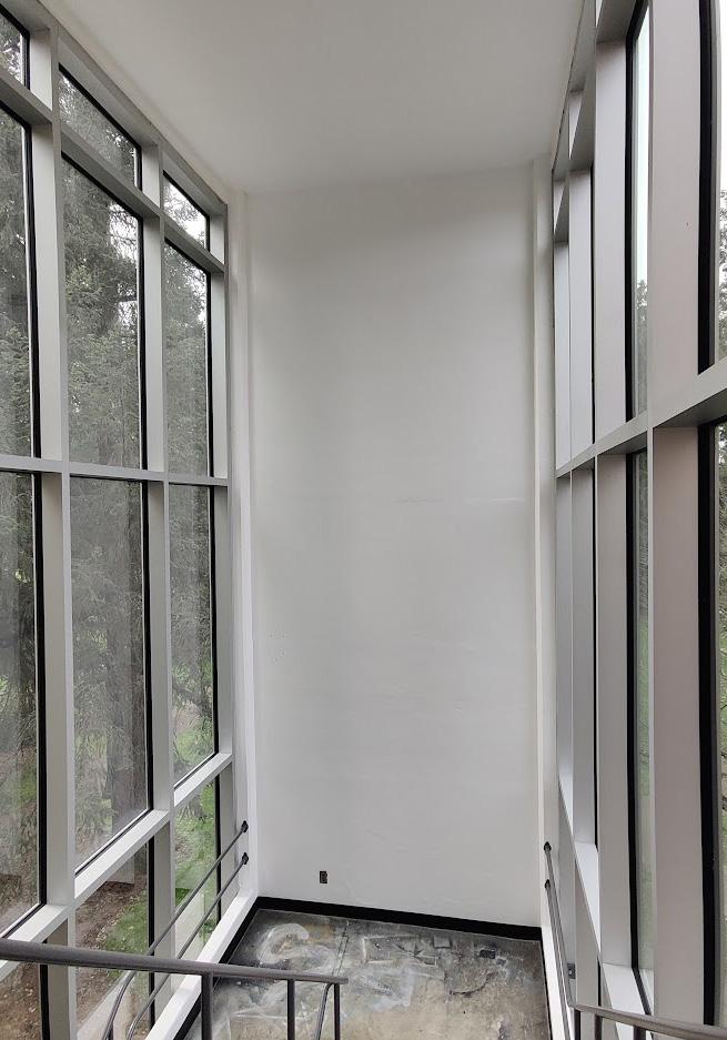
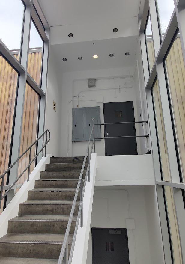
IMAGE: lidar model
DIGITAL MODELS
MODELING A SPACE IN LAWRENCE
LIDAR
Using a phone with lidar capabilities, we scanned the staircase to make a lidar model.
DIGITAL
TWIN
The amount of glazing within the staircase gave lidar scanning some trouble. Therefore, I decided to make a digital model using a combination of measurements I took and the lidar model.
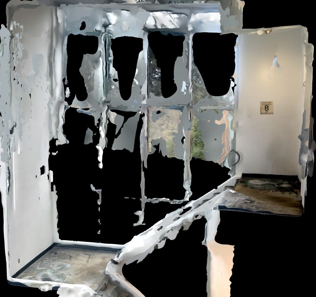
IMAGE: digital twin with existing conditions
TECHNICAL DRAWINGS
EXISTING CONDITIONS
The technical drawings here show the existing conditions of the staircase. The area of study is the west wall. The color coding follows the key on page 33.

COMPONENT PATTERN
ANALOG 2D PATTERN STUDIES
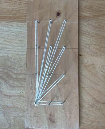
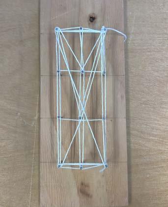
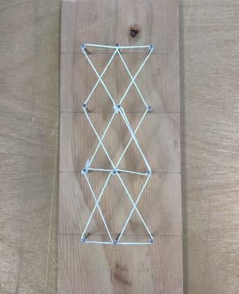
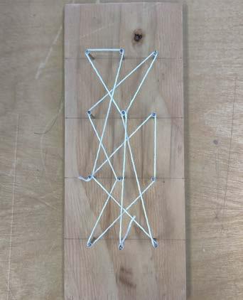
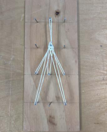
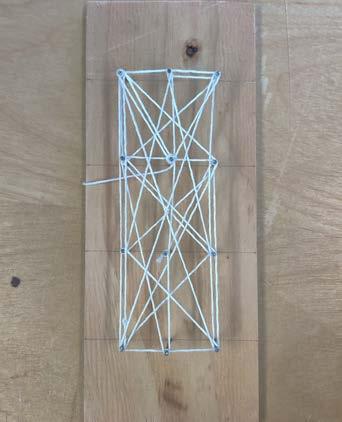
After selecting a space within Lawrence Hall, we began with analog studies using string and nails on a board. It informed us on how to activate the space with patterns for living systems. For this exercise, I opted for a 2’x4’ grid.
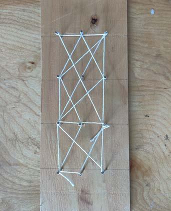



IMAGES:
10 different studies of patterns within the selected space
COMPONENT PATTERN
DIGITAL 2D PATTERN STUDIES
To start the digital exploration of 2D patterns, we developed a series of modules in Rhino. I developed 3 2’x2’ modules instead as it would allow it to be fully rotated about their x and y axis and fit the same space from any direction.
MODIFYING THE PATTERN
After developing the modules displayed, I developed the 1st iteration of the 2D pattern. It went through several iterations to account for water flow and the integration of plants which will be shown in the following pages. The final pattern here determined the placement of the building systems.
Module A Module B Module C
IMAGES: proposed modules (left) original iteration (right)
IMAGES:
2nd iteration (left) final iteration (right)
IMAGE:
digital analysis of midterm design
WATER FLOW ANALYSIS
DIGITAL SIMULATION
Using Grasshopper, a parametric modeling tool within Rhino, I ran a plugin called Groundhog to simulate surface runoff. This would analyze how water would run through my designs. The goal was to get the water to run to any openings. Running it for the midterm design allowed me to see where issues with flow were occurring so I could address them in the final design. The major areas of concern are indicated in red dotted circles.

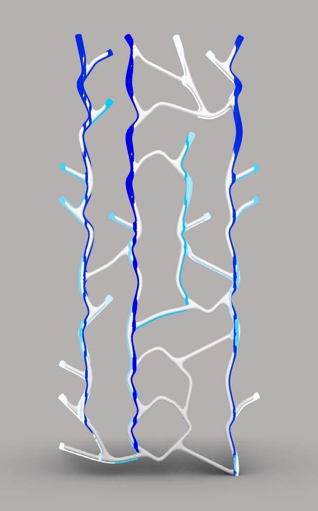
IMAGE: digital analysis of final design
SUNLIGHT ANALYSIS
MEASURING WITH A LIGHT METER
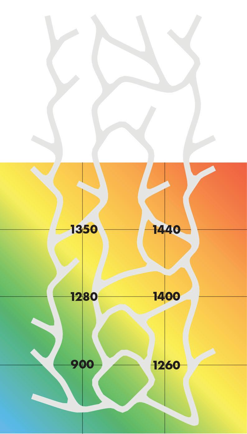
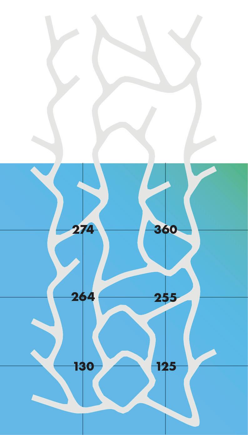
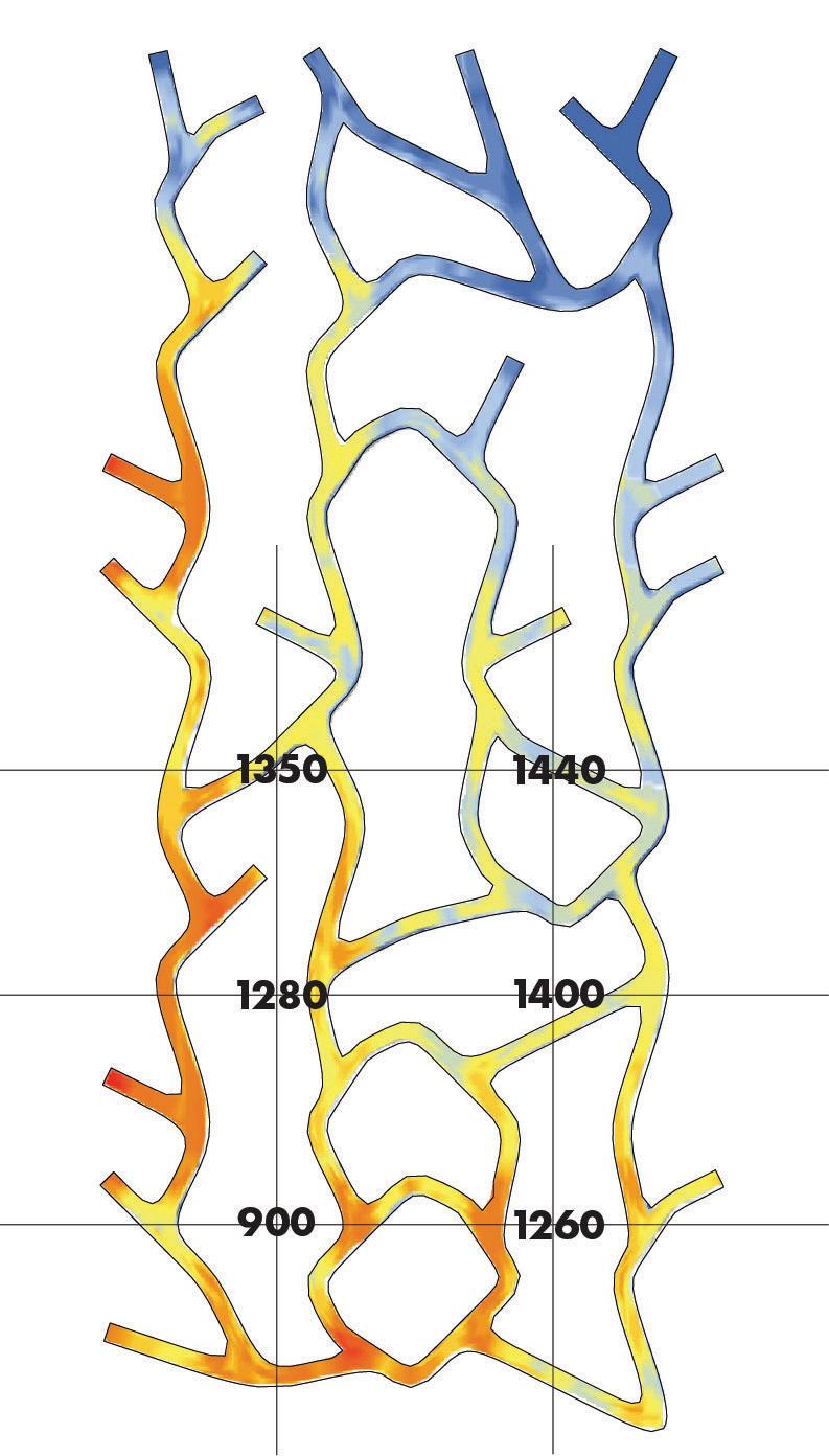
We used a light meter to acquire lux readings in the selected space in real time conditions. I could not acquire lux readings for the entire space as I couldn’t reach the taller end of the vertical space.
SUNLIGHT ANALYSIS
SIMULATING SOLAR & COMPARISON
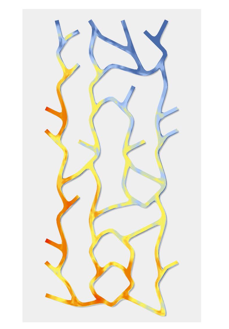
I used Heliotrope which is a Grasshopper plugin to simulate the solar conditions within my chose space. The plugin includes a suite of geometric solar analysis tools that calculate solar vectors and projected geometry for dates, times, and locations. Here I looked at the average within a year.
COMPARING ANALYSIS METHODS
Page 41 displays the lux readings from the afternoon overlayed on the simulated average within a year. In the real time conditions, the darkest spot seems to be the lower left while the simulated version shows the top right corner as being the darkest spot. It is possible for both analysis to be accurate as the lux readings were done in February when the sun is lower in the sky for the Northern Hemisphere. Additionally, the simulated version does not include the 2 tall trees on either side of the staircase which would block some light.
PLANTING PLAN
DESIGNING THE ARRANGEMENT
With the sunlight analysis done, it was determined the space is ideal for plants that need bright, indirect light. Though all the plants selected can live with 10,000 to 20,000 lux, there are more optimal requirements. With an average of 10 daylight hours between November to April, the selected plants will need about 10,000 lux in supplemental lighting to meet energetic needs.
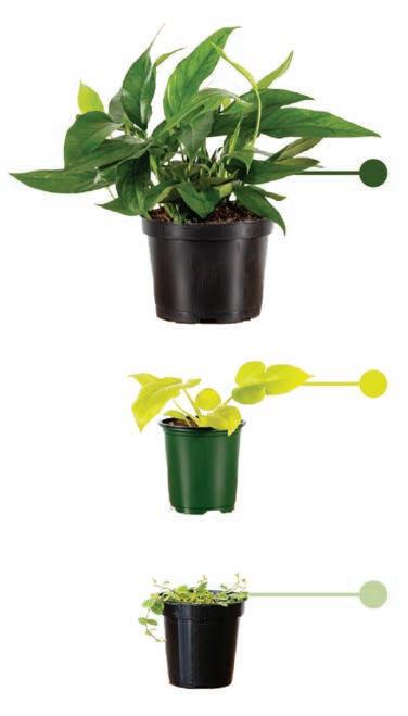
I wanted plants with a bright, bold color as the space is painted white and washed with light. The Baltic Blue Pothos has deep green leaves and will have a blue highlight when it grows in medium light instead of bright. It is a climbing plant and the leaves will fenestrate as they mature. The bold chartreuse color of the Philodendron Neon Selloum creates a nice accent with the blue highlights of the Baltic Blue Pothos. It is ideal in a medium to bright light. To add a smaller texture to contrast the bigger leaves of the other plants, I opted for the String of Turtles. It is optimal in the brightest light and the little leaves are patterned with a few colors.
SECTION DETAIL & ROOT DIAGRAM
With the Baltic Blue Pothos, I took a closer look at how it would interact with my component scaffold design. It did not require a mesh to hold the plant in place, but could prove beneficial. The pipe strap is explained in greater detail on page 48. The Baltic Blue Pothos averages 1-2’ roots and even up to 3’ in the best conditions. When grown in a pot, it’s easily root bound if the pots aren’t changed. In this design, they are free to explore greater lengths.
BALTIC BLUE POTHOS
Epipremnum pinnatum ‘Baltic Blue’
15,000 lux/day
PHILODENDRON NEON SELLOUM
Philodendron bipinnatifidum ‘Gold’
18,000 lux/day
STRING OF TURTLES
Peperomia prostrata
20,000 lux/day

PLANT PALETTE

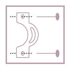
pipe strap to wall
closer look at pipe strap
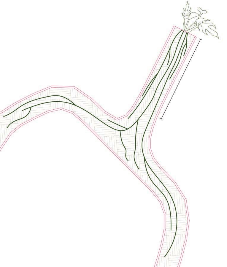
Baltic Blue Pothos
concrete wall
3” PVC pipe soil
PROPOSED SCAFFOLD
WITH PROPOSED BUILDING SYSTEMS
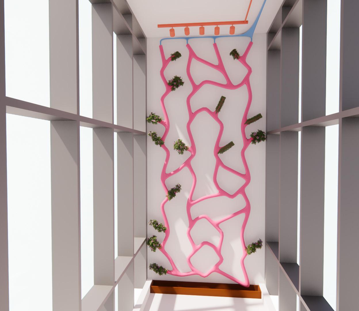
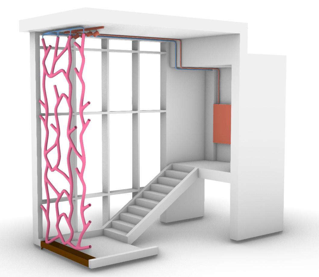
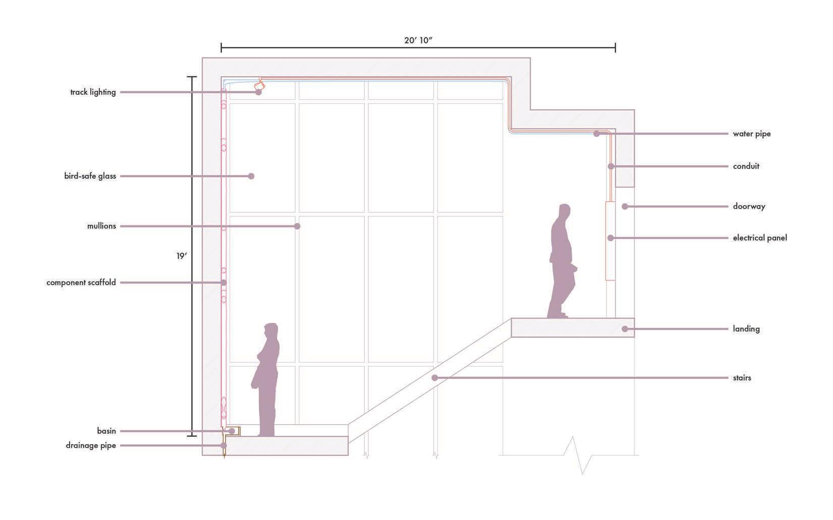
Here is the final iteration of the scaffold in the context of the digital twin model. The proposed building systems are modeled to fit the proposed scaffold. The track lighting pulls electricity from the existing electrical panel. Water pipes don’t exist on the opposite wall but I would assume that it would most likely be pulled from that side as well. The drainage system is proposed to run straight down to the lower level and out on the north side through the thick concrete wall. This is because on the other side of the selected space is a sculpture and the north side is fully glazed but has a concrete wall that is thick enough for the proposed drainage pipe to run through. The colors follow the key displayed on page 43.
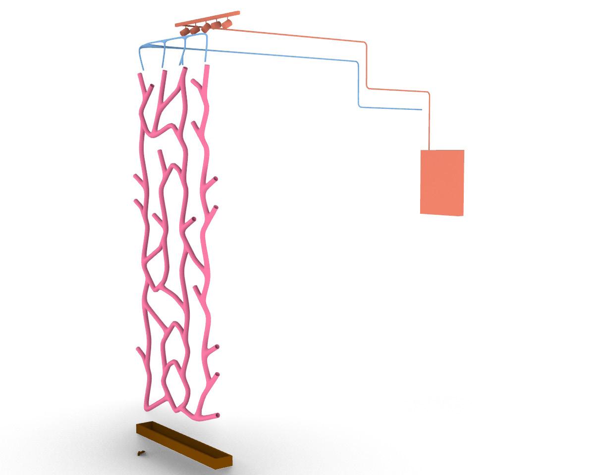
SYSTEMS AXONOMETRIC
Page 43 is the exploded axonometric of the proposed design. It includes the proposed attachment placement which would be galvanized steel pipe straps that are ideal for wall mount and used with PVC. They would be painted white to blend in with the existing wall and PVC.
The color key here is followed throughout the booklet to represent the component scaffold and building systems.
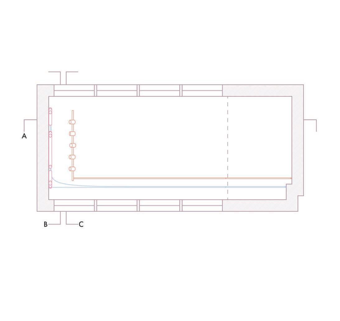
TECHNICAL DRAWINGS
SECTIONS & PLAN OF PROPOSED SPACE
The technical drawings here show the proposed component scaffold and building systems in Lawrence Hall.


1:1 BUILD DESIGN
USING OFF THE SHELF MATERIAL
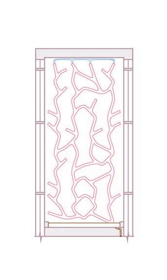
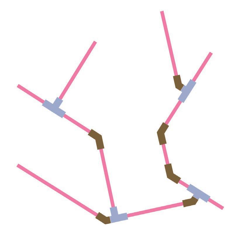
Due to time constraints, availability, and costs I did my 1:1 component prototype in a 1” diameter pipe. The angles in my proposed component scaffold can’t be achieved with off the shelf fittings so I customized fittings to be as similar to the original as possible. Using the 2 fittings shown on the right, I sanded them down and connected them using a small piece of 1” PVC to make fittings fit my needs. Here you can see how the build design differs from the original design. The acute angles were the hardest to replicate.
customizing fittings
1/4”
1/4”
1/4”
1/4”
PARTS LIST
2 - 1” x 10’ PVC Pipe
4 - 1” PVC tee
6 - 1” PVC 45° elbow
COMPLETED BUILD
CONSTRUCTION & PLANTING
There were no major issues in constructing the build with custom fittings. Sanding the PVC fittings must be done in intervals as it can overheat and melt. Afterwards, I had to sand the inner edge as it lost its lip during the process and to slip the small piece of pipe into the other fitting.
PLANTING THE BUILD
For the time frame we are working with, I used chia seeds in some openings as it grows quickly. In the openings that match the original design, I planted Golden Pothos to get a sense of proportionality. The plantings dry out quickly in a 1” diameter design therefore it has to be frequently watered.


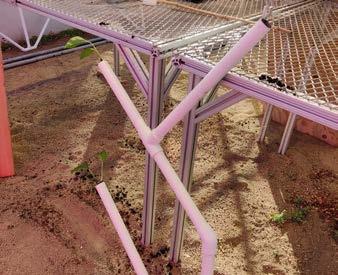
IMAGES: finished build in greenhouse (left & bottom) constructing build (top right)
IMAGES:
mesh to hold up planting (top left) plant growth over 2 weeks (chronological)
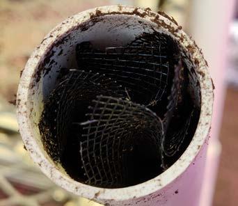

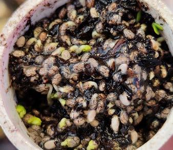
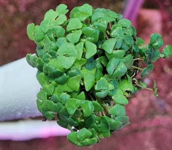
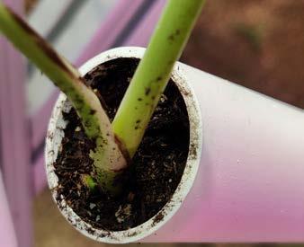
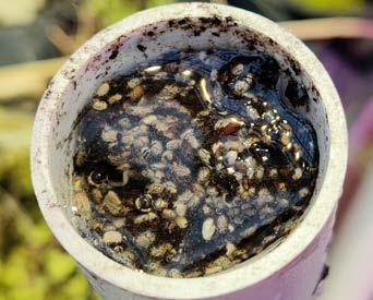
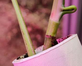
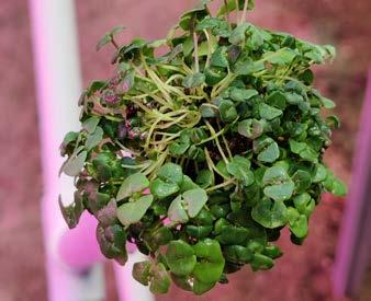
IMAGE:
render with all building systems in view
FINAL RENDERS
PUTTING EVERYTHING TOGETHER
Here are some rendered views with the final component scaffold design. The plants represent an initial growth.
MATERIALITY, SIZING, & OPENINGS
For this project, I imagine that the component scaffold would be made of high grade PVC. It can be food safe and commonly used for different gardening methods such as aquaponics. PVC is affordable compared to other materials and sturdy. A 3”+ diameter pipe should be sufficient enough for the plants selected. Propagated cuttings can fit those openings and the roots should have no issues as it is not bound to a pot. The use of the entire vertical space allows for the plants to do plenty of climbing across the component scaffold.
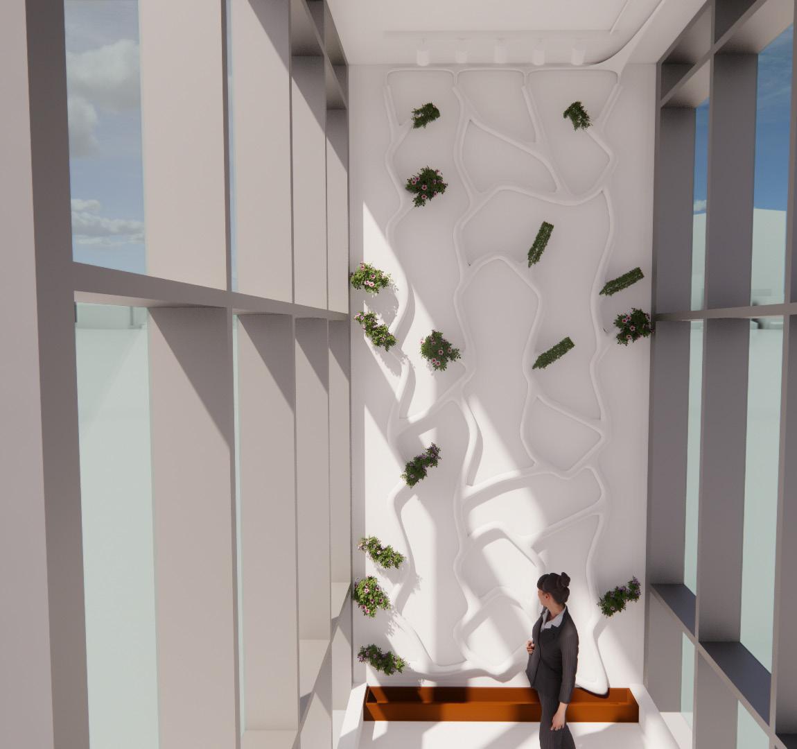
IMAGE: render looking closer, upwards
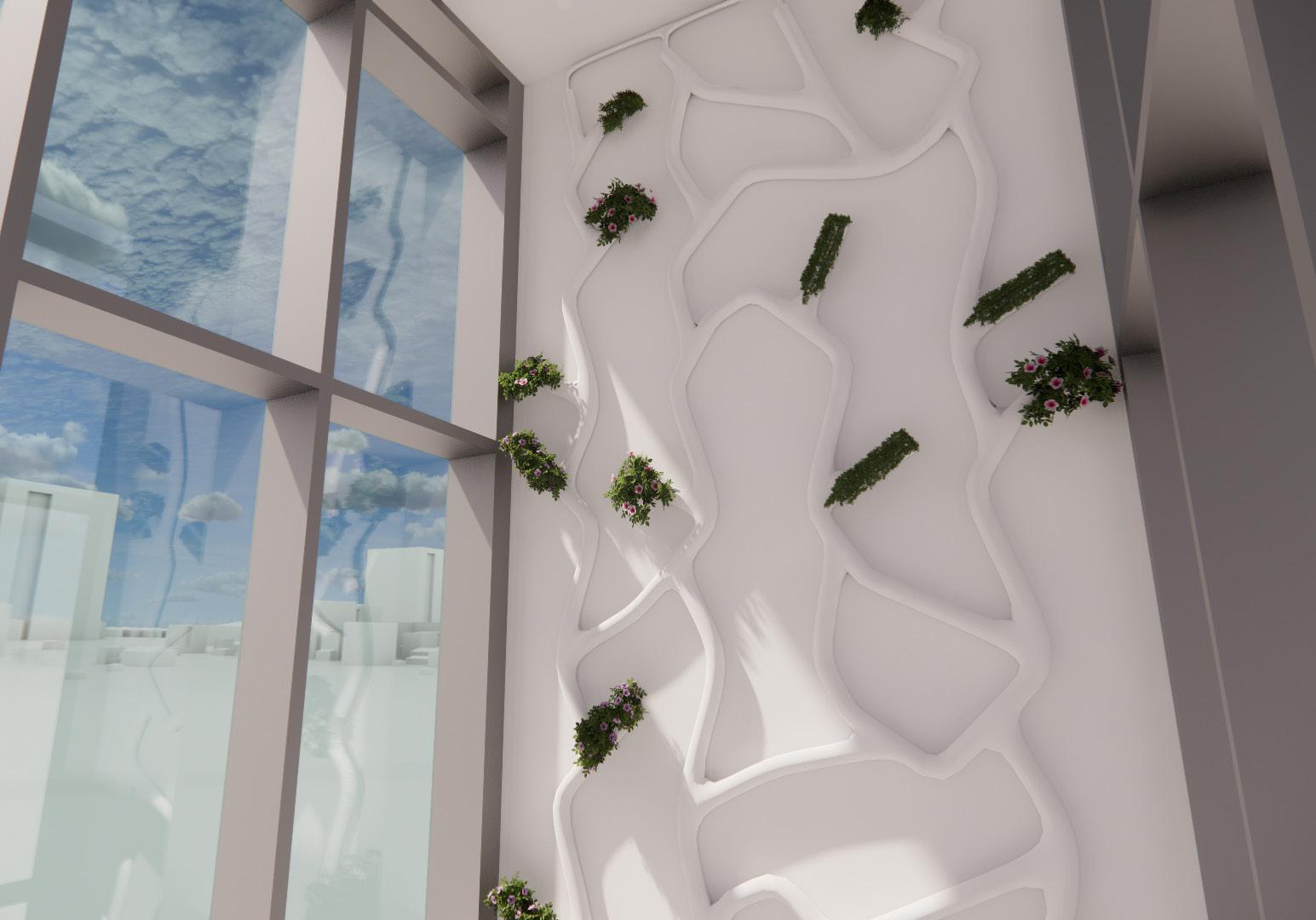
IMAGE:
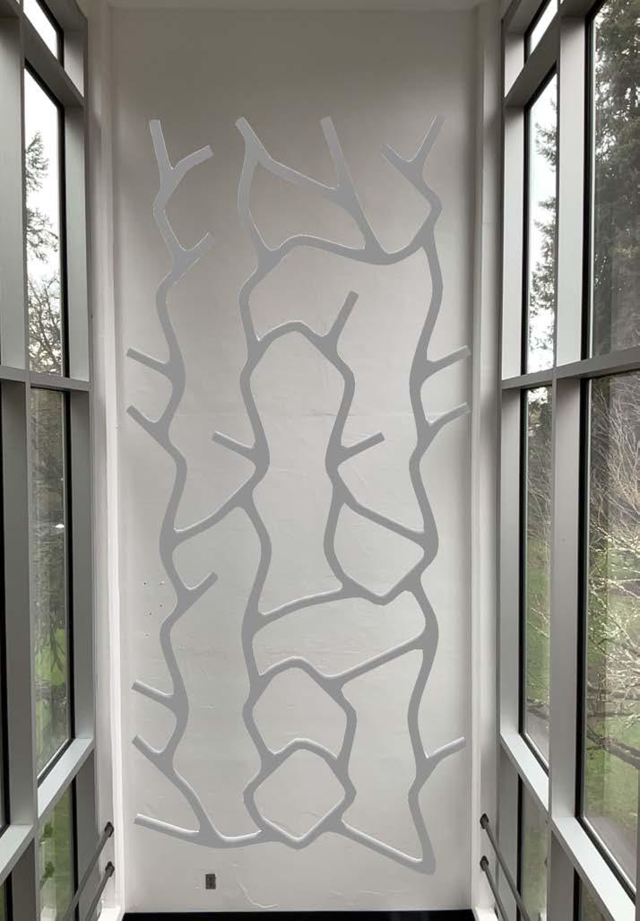
fologram capture looking straight forward
VIRTUAL REALITY
PUTTING IT IN REAL TIME CONTEXT
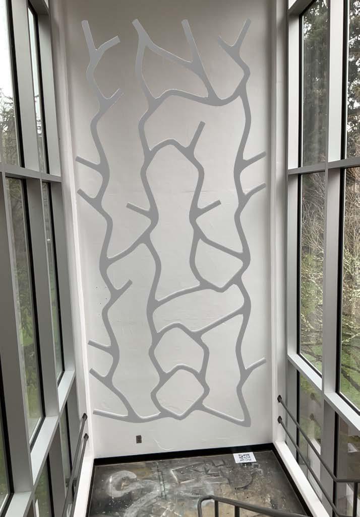
Fologram is the program we used to show mixed reality. I was able to add my component scaffold to the existing space, but there were quite a few issues that came about. The model must have a limited number of faces as to minimize glitching and other errors. My space in the staircase is a drop off point for wifi therefore I needed a hotspot to support the connection for my laptop and ipad. With the hotspot, it was successfully viewed in the space. However, placement and drop off were still an issue. The placement QR was to be place on the landing
where it is designed, but it’s difficult to view the whole design while standing there. To view the whole design, I had to move on the landing above. I could not lose sight of the placement QR code though or the model would move. It took a few tries to get the whole model within frame. The model does still slightly move with the placement QR, but that is currently a given flaw.
IMAGES:
capture from left of 3rd floor landing capture looking left towards windows
SCAFFOLD MODULES
ALTERNATIVE APPLICATIONS
Here I explored alternative applications for the scaffold modules I designed in different settings. They look at different size modules, attachment styles, and environment materiality.
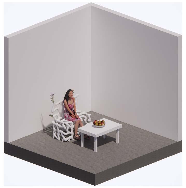
1 FURNITURE DESIGN
For the furniture application, I explored the design of a bench. This was done with 1/4 scale modules to create a denser area for structure and seating. This could possibly used in a lobby with a concrete floor since it is permeable or an exterior application.
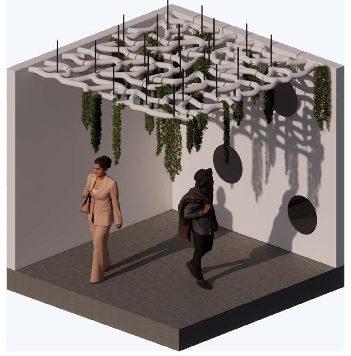
2 CEILING APPLICATION
This drop ceiling design looks at hanger attachments to hang the scaffold. This was done with 1/2 scale modules. It allows for greenery without taking horizontal space. This could possibly used in a lobby as well, particularly in a corner with concrete as a more interactive space or a point of interest.
3 ROOM DIVIDER
For the room divider design, I looked at using multiple scale modules to create a stronger structure and a gradient of privacy. This could be ideal for a gallery as a more sculptural style divider. It was done with original scale modules and 1/2 scale modules as the connection points matched.
1 FURNITURE DESIGN

2 CEILING APPLICATION
3 ROOM DIVIDER
IMAGE: 1/2 scale physical model
PHYSICAL MODEL
PUTTING IT IN CONTEXT
To aid with the component scaffold design process, I build a 1/2 scale model out of museum board. Page 65 shows the component scaffold design 3D printed with PLA and placed into the model.
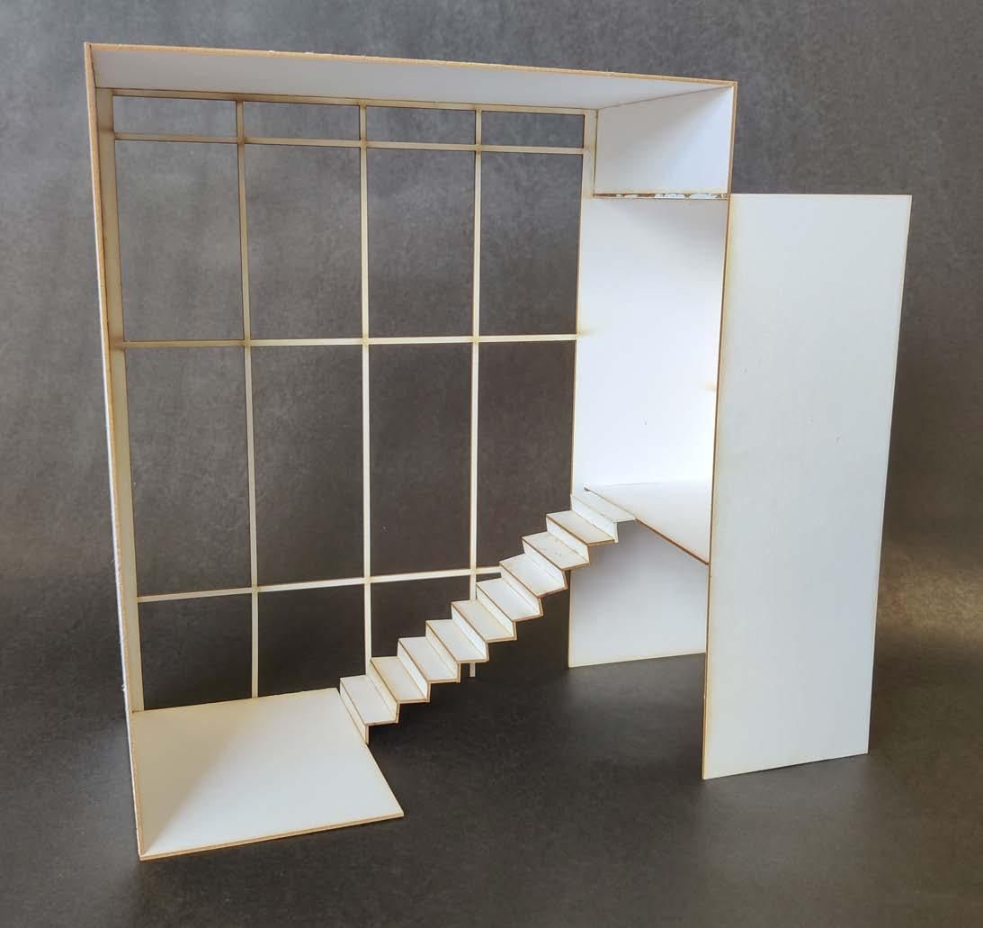

IMAGE:
1/2 scale physical model with scaffold (left) 1/2 scale with scaffold close-up (right)

IMAGE: render view with color coded systems
CONCLUSION
& POTENTIAL EXPLORATIONS
This studio has allowed me to explore how scaffolds can provide a better solution for living systems inside the architecture we built. These scaffold modules can be used for more than replacement of green walls. Further explorations in module sizes can allow for additional applications.
POTENTIAL EXPLORATIONS
With a longer timeline, I would like to explore the viability of a transparent system. Clear PVC and water beads would allow for us to see the entire root system of plants and see how it grows into the component scaffold design. Water beads are excellent for retaining water to maintain moisture. However, they don’t provide the same nutrients that soil can. Additionally, the possibility for a transparent attachment style must be further researched to achieve a fully transparent system.
