ABSTRACT
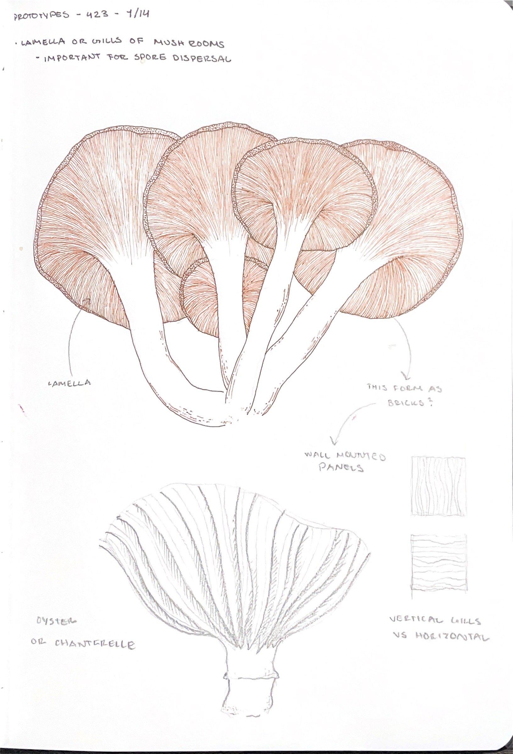
“Lamellae Wall” looks at the form of the lamellae of mushrooms as a concept for a biophilic living wall system. The aim of the project is to explore this form to create a lightweight, wall mounted structure to house a variety of soil-less air plants using natural materials. Research for fabrication stems from a variety of projects that incorporate a double curved geometry with parametric waffle systems to generate an organic, interlocking form. The projects researched also looked at and drew inspiration from acoustic ceiling panels as well as how other living systems have incorporated air plants as their “living” component. Methods of fabrication for the project combined the findings from the facade design of Guys Hospital by Heatherwick Architects with the parametric waffle system for an integrated approach to a living wall. The proposed material for fabrication will be laser cut wood panels that join together with geometries created in Rhino and Grasshopper with a wire mesh adhered to the back.
fig. 1
1. Photo: Lamellae Diagram, Mark W. F. Fischer
ROOFTOP AIRPLANT VERTICAL GARDEN
fig. 2
fig. 3
fig. 4
fig. 5
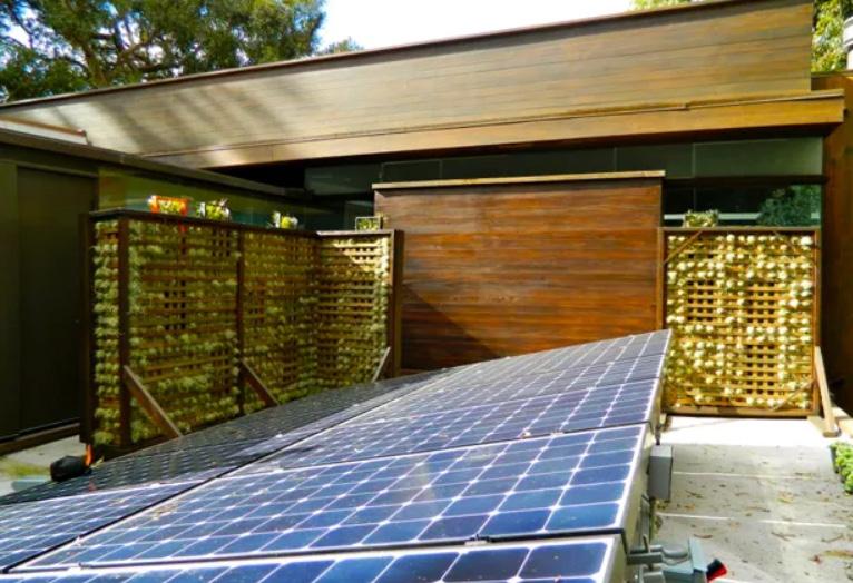
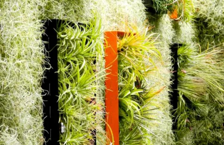
This project utilizes a trellis system to create a space for air plants to latch onto an grow. Since the trellis is not a solid object or structure, the spaces between the planks of wood allow air to pass and flow through which is necessary for the health of the plants in the system. A number of different air plants were used as well as incorporating Spanish moss for background filler.
This project has a few important aspects that can be integrated into the living wall prototype. First, the use of plant type is important to note. Since air plants do not require soil, it creates some flexiblity for the proposed structure as issues of weight and water are not a prevalent. The trellis system in this project is fairly lightweight and vertical. Similar to how the trellis has overlapping
wood slats to create a paneled form, the waffle system analyzed in other projects fits within this typology.
fig. 6
2-5. Photo: Rooftop Airplant Vertical Garden, Ray Kappe
6. Sketch: Rooftop Airplant Vertical Garden diagrammatic assembly sketch, Madison Young
fig. 7
fig. 8
fig. 9
fig. 10
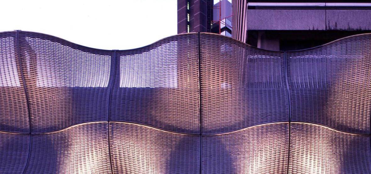
The facade remodel of Guys Hospital by Heatherwick Architects incorporates the use of double curve geometries to create a dynamic building skin. The facade system utilizes steel as the primary material for construction with meshes, cables, and plates. The plates appear to provide the framework for the form, creating a curved structure that is able to be filled in with the meshes
and cables. Each semi transparent panel of the facade acts to create a “breathable” system for the boiler room that sits behind it.
Key takeaways from this project are in regard to the fabrication concepts for the facade panels. The steel frame with a mesh-like material that sort of “creates” the form was interesting to look at and apply to methods
of fabrication for a wall system. Though materials will be different (wood instead of steel) the concept of creating a frame with an organic form will be applied to prototype options. The use of the woven steel mesh that was used in the facade of Guys Hospital will be applied to a new concept of “holding in” plants to the living wall.
7. Photo: Facade prototype - Guys Hospital, Heatherwick Architects
8 & 10. Sketch: Facade diagrammatic assembly sketch, Heatherwick Architects
9. Photo: Guys Hospital Facade, Heatherwick Architects
11. Photo: Guys Hospital Facade, Heatherwick Architects
fig. 11
MESHWAVE AND WAFFLE WALL
fig. 12
fig. 13
fig. 14
fig. 15
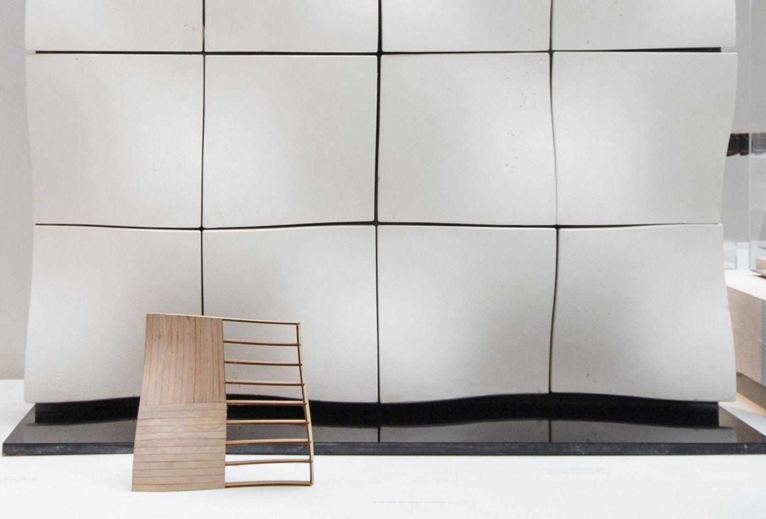
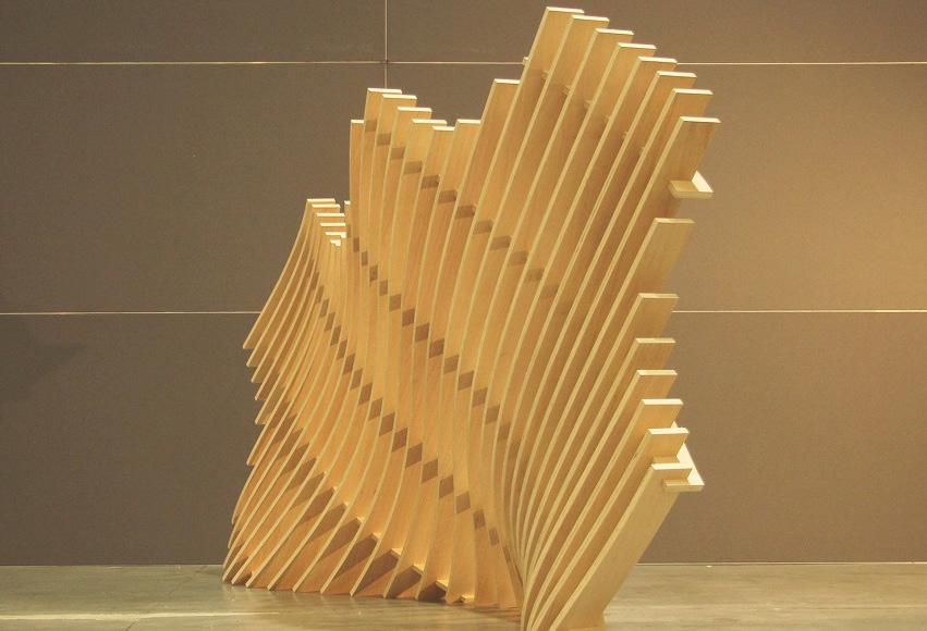
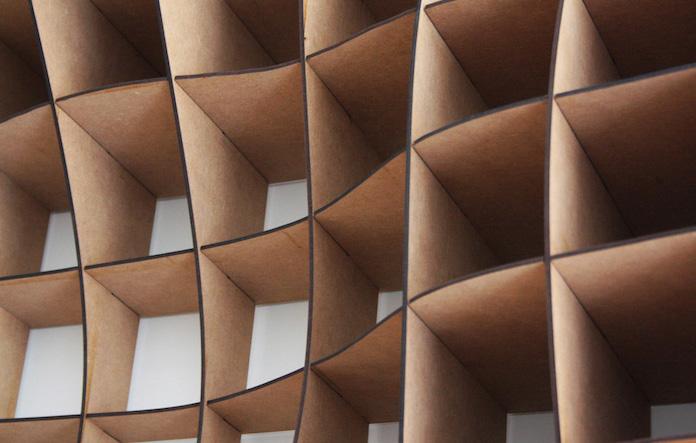
Projects Meshwave and Waffle Wall both look at different applications of the waffle method of fabrication. Both projects implement the use of Rhino and Grasshopper to generate the forms and connections.
The importance of these two projects for concept development of the prototypes revolves mainly around the fabrication method. To generate a structural framework for
the wall that uses the form of the lamellae of a mushroom, the use of plugins and programs that have parametric elements are necessary. Taking the framework idea from the facade system of Guys Hospital and combining it with the parametric waffle system shown in Meshwave and Waffle Wall, the preliminary prototype for the living wall can be formed.
fig. 16
fig. 17
fig. 18
12. Digital Model: Waffle Wall, by Unknown
13. Photo: Waffle Wall physical model, by Unknown
14-15. Photo: Meshwave model, Pier Luigi Forte
16-18. Photo: Meshwave models, Pier Luigi Forte
METHODOLOGY
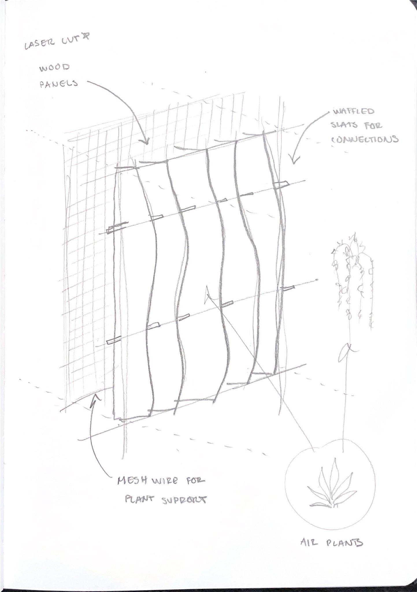
The preliminary method of fabrication for this living wall system is to create a waffle grid pattern that interlocks using Rhino Grasshopper with the intention of creating a lightweight structure to accommodate a variety of air plants.
Initial prototypes of the wall system will be fabricated out of chipboard to explore forms with a lower cost material. Different spacing of the grid system will be tested to determine the most effective shape for structure and stability, weight, and the ability to create a secure space for plantings. Additionally, a prototype that includes molding and bending the chipboard pieces together to create pockets will be tested for the integration of plants to the system. These models will be assembled and prepped via laser cutter.
The final materials proposed for this will be wood sheets or panels that will be also be laser cut to lock together. A variety of air plants will be placed into the system to finalize the living wall concept.
19-20.
21. Sketch: Preliminary prototype sketch, Madison Young
Sketch: Preliminary concept sketch, Madison Young
ARCH 423
Scaffold Assemblies
SCHEDULE AND PROCESS
The phases of this project include Research and Investigation, Fabrication and Testing, and Exhibition.
Initial stages in research and investigation have been completed over the past three weeks which have led to a research topic concerning the form of a mushroom lamellae and how it could be incorporated
into a living wall system. Materials, a working design, and methodology have been decided in this stage.
The following weeks leading up to the exhibition will be primarily for fabrication and testing of three different prototypes. Initial modeling in the digital realm will be the first step in this phase to generate forms and get ready for laser cutting. Fabrication of the prototypes will follow the digital models to test how they work
physically with the goal of creating a lightweight structure for air plants. The final phase will consist of analysis of findings from the prototypes of the previous phase. A final presentation will be compiled followed by set up for the exhibition.
MATERIALS
Chipboard (1/16” thick) x2
Tillandsia - Spanish Moss
Old Man’s Beard Lichen
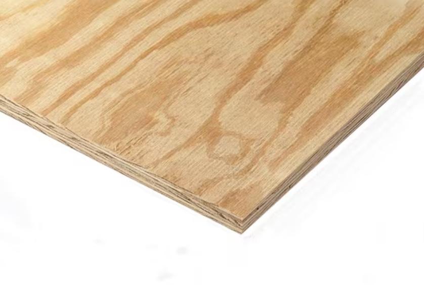
1/5” x 4’ x 8’ plywood panel x1
Wood Glue
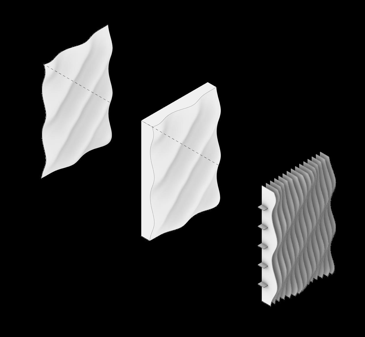
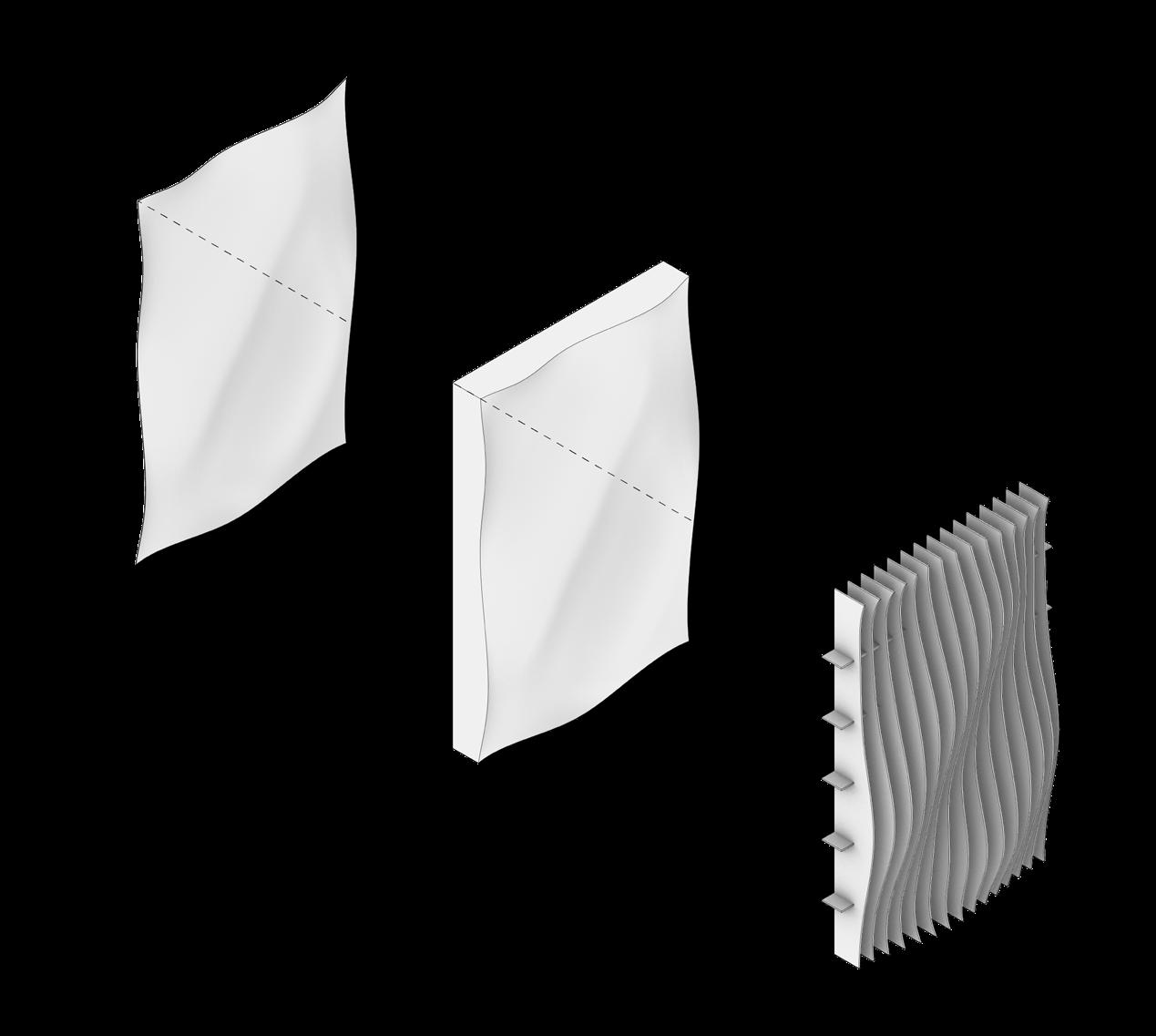
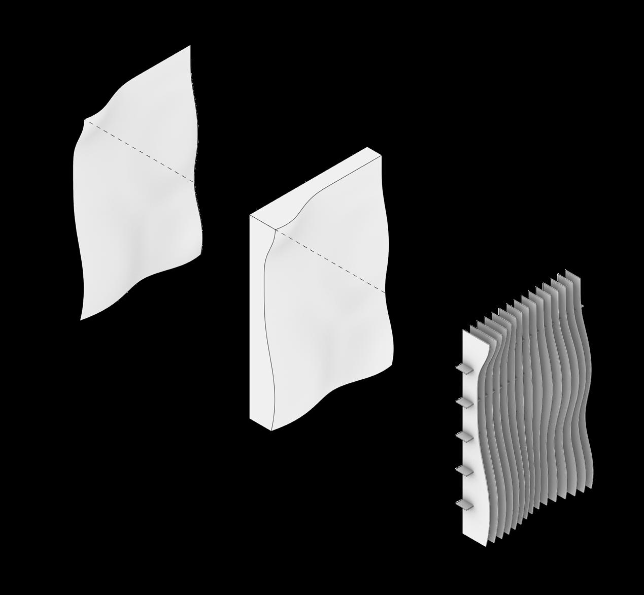
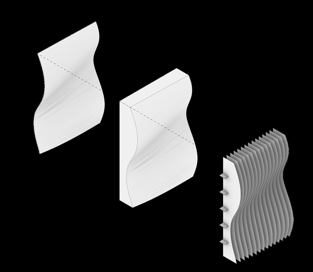
To create the digital models for the prototypes, a surface was created three different ways to see what forms could be generated. The first method, shown in diagrams above, started with a surface that was rebuilt to establish a grid of points to be manipulated. Manually, the points were pulled up and down to get the rippled surface. Three different versions of this method were tested with varying degrees of rhythm and
randomness within the extrusions. The surface was then turned into a polysurface through lofting to be able to be plugged into a grasshopper script to generate the panels.
fig. 22: Digital Prototype 1
fig. 23: Digital Prototype 2
fig. 24: Digital Prototype 3
TESTING: Digital Modeling
The second method of digital modeling for the prototypes was similar to the first where a surface was created and rebuilt with a number of points to be manipulated. However, rather than selecting each point individually to move it up or down, the soft move command was used to even distribute the hills created in the surface. The result was less exaggerated in the overall form with fewer valleys. The third method used was to
was to create two curves and loft them to get a surface rather than creating curves from points. The result of this method was larger, softer waves of the surface. For both the second and third methods, a grasshopper script was used to create the waffle grid panels from the polysurfaces. Since the intention of the prototype was to replicate the form of mushroom lamellae, the horizontal panels were made smaller to allow the vertical panels to have the most definition of shape while maintaining enough structural support to hold together. The final form and method selected was the first method that created the prototype with the diagonal curves. This form felt the most dynamic in shape while maintaining the concept of the lamellae.
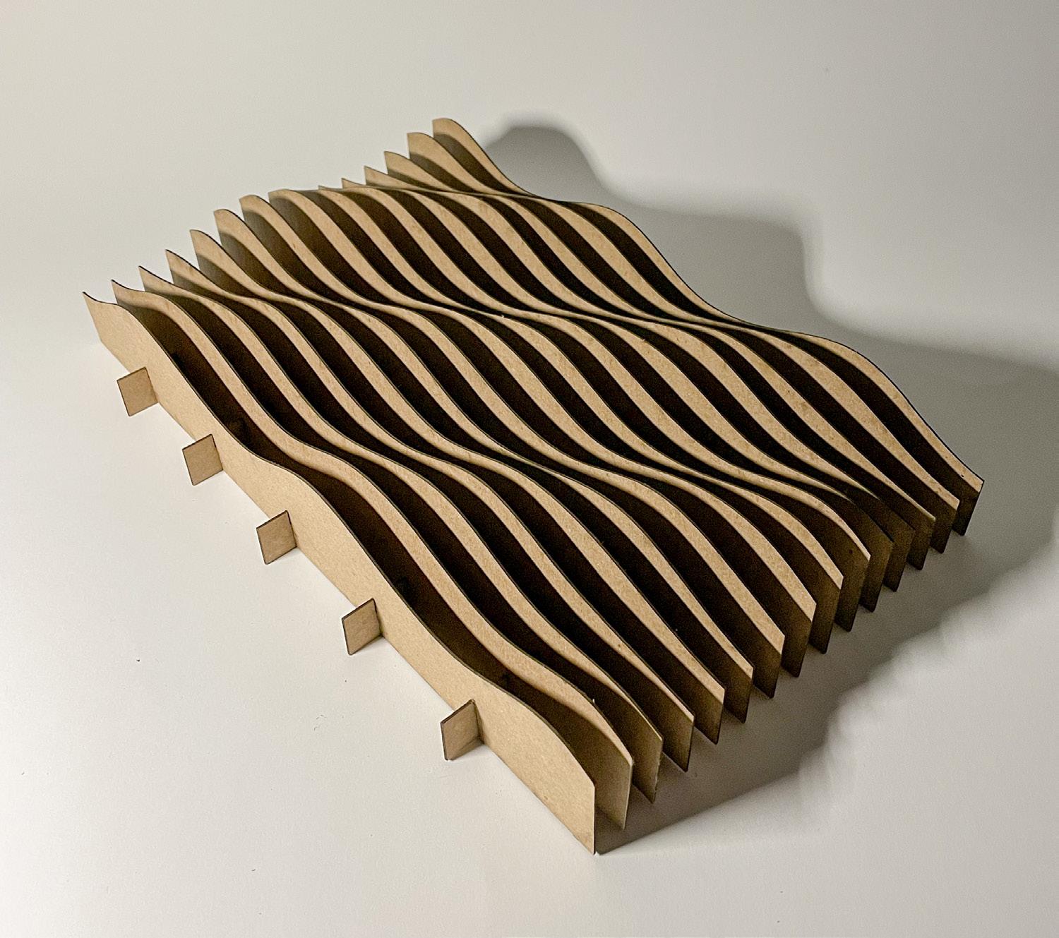
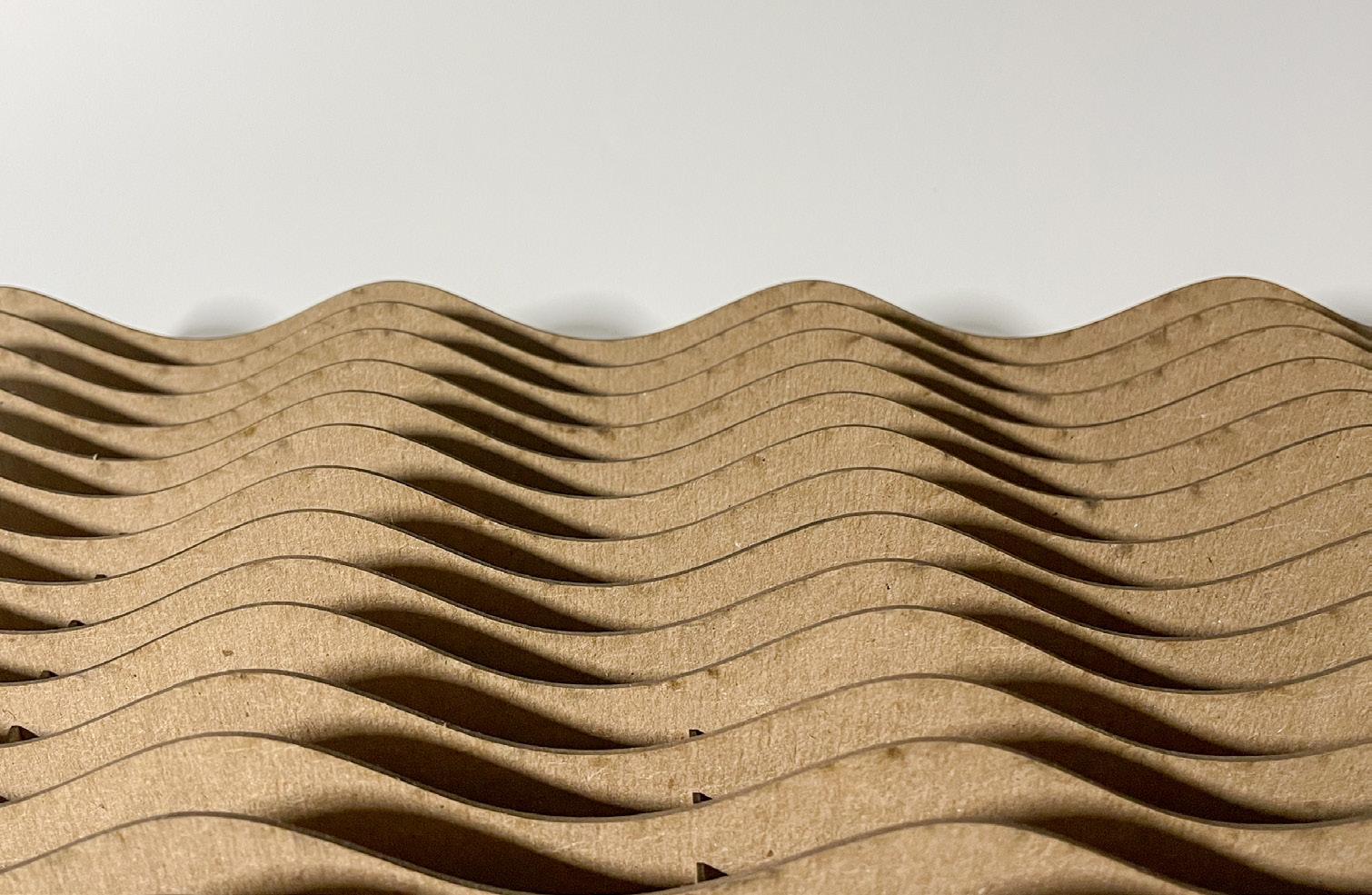
To begin moving the prototype from the digital realm to the physical, chipboard and a laser cutter were used to create the model. Using the digital model created with Rhino and Grasshopper, a laser cutting file was set up that would allow the pieces of chipboard to lock together. One main problem that was discovered with the physical model was lateral movement. Though there were horizontal and vertical elements, the model was
not very stable on its own by simply connecting the pieces together. To solve this, a small amount of glue was used to hold all the elements together. This finding will be beneficial when moving to the full scale prototype as stronger connections will have to be developed to ensure the overall structure.
fig. 27: Physical Prototype 1
fig. 28: Physical Prototype 1
TESTING: Physical Fabrication
Moving forward, the full scale prototype will be CNCed out of plywood measuring 18” x 36”. The use of various kinds of tillandsia will be the planting of choice for this living system as they fit within the thin vertical spaces defined by the panels. Air plants are also very lightweight and do not require a growth medium or large quantities of water to thrive, allowing the prototype to maintain its delicate form.
fig. 29: Physical Prototype 1
fig. 30: Physical Prototype 2
fig. 31: Physical Prototype 3
fig. 32: Close up of Physical Prototype 1
fig. 33: Close up of Physical Prototype 3
fig. 34: Physical Prototype 4
CNC
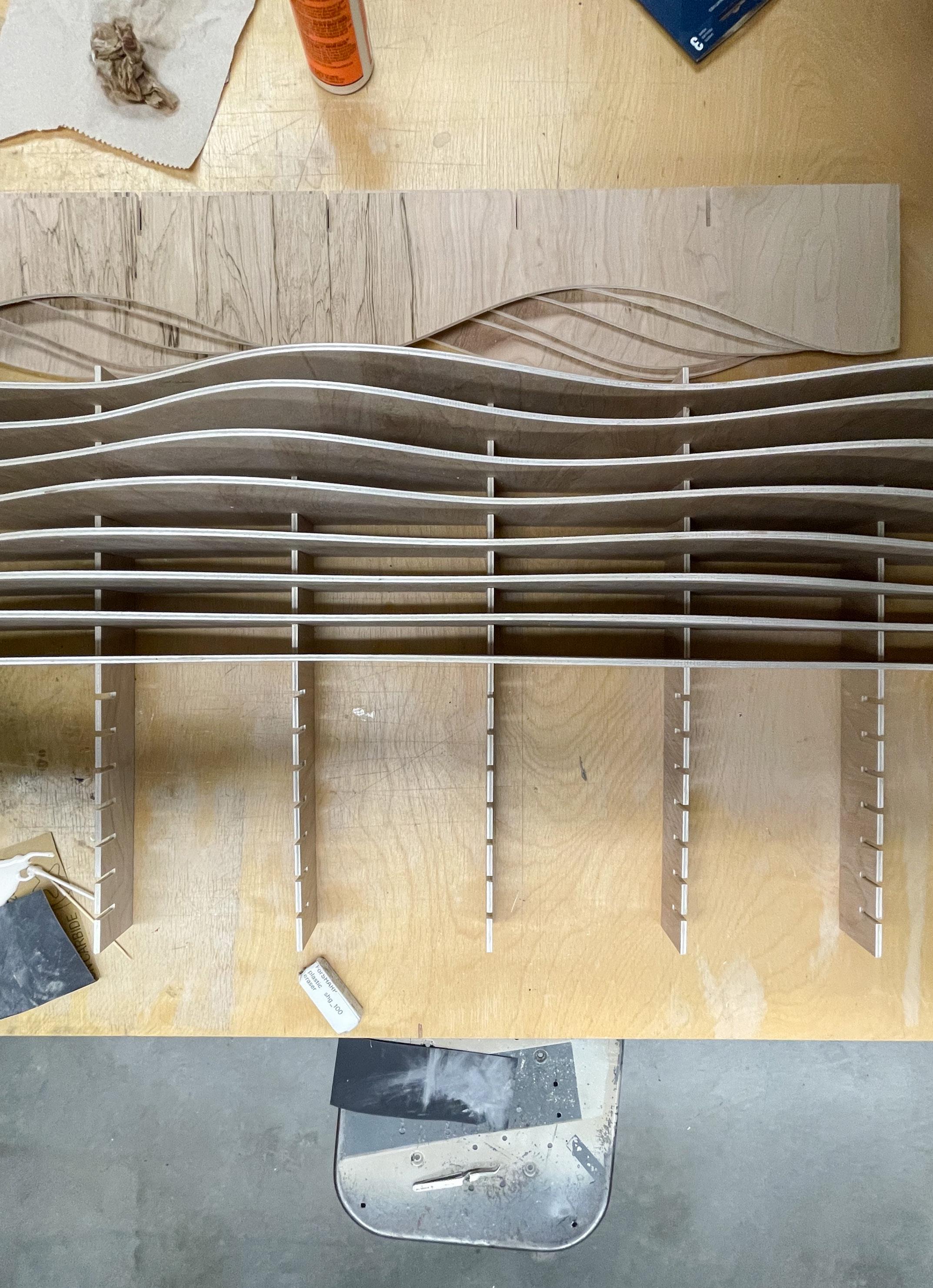
The fabrication process for the fullscale prototype relied on the use of a CNC machine to cut out the vertical and horizontal elements. Using the digital model from Rhino, a file was created of the series of cuts to make with the CNC machine taking into consideration the thickness of the material as well as the dimensions of the print bed. A 4’ x 8’ sheet of
1/5” plywood was used in the final fabrication process which was able to fit an 18” x 36” prototype. Each of the vertical fins measures at the lowest point 2 inches and at the highest, 4 inches. The horizontal components were each 1.75 inches to allow more visibility with the vertical elements.
fig. 34: CNC Fabrication
fig. 35: CNC Fabrication
ASSEMBLY
The assembly process for the prototype was fairly simple as much of it was locking the elements together through a series of slats created in the components. As learned from the fabrication of the chipboard prototypes, glue is needed to provide slightly more support between the “gills” to prevent lateral shifting.
fig. 36: Assembly of CNC’d parts
fig. 39: final prototype
fig. 37: Close up of final prototype
fig. 38: Close up of final prototype
CONCLUSION
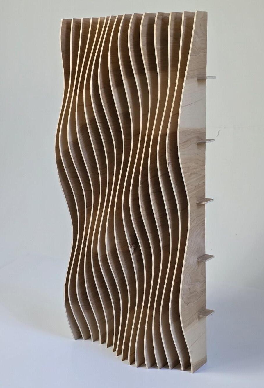
The final prototype for this living wall system inspired by mushroom lamellae came together with the use of digital and physical fabrication methods. The prototype measures 18 inches by 36 inches, comprised of a series of vertical elements designed to reflect the form of the lamellae. The vertical components are joined together in an interlocking waffle system and held together using wood glue for extra support.
The design process began with analyzing the form of different species, ultimately deciding on the gills of a mushroom as the leading concept for the design. Final materials and fabrication methods were chosen to best reflect the shape of the lamellae which ended up being 1/5” plywood and CNC. Air plants were selected as the species of choice for the living system as they do not require large quantities of water or soil, allowing the structure to keep its lightweight frame.
Before final fabrication and assembly, chipboard test models were created to identify any issues that might come up with the full-scale prototype. The test models were also used to look at the different form options. After solving some structural issues noticed in the models and deciding on a final form, a delicate full-scale prototype was able to be created that imitates the intricacy of the mushroom lamellae.
Figures and Photos
1. fig.1: Lamellae diagram, Mark W. F. Fischer https://www.ncbi.nlm.nih.gov/pmc/articles/PMC2891949/
2. fig 2: Rooftop Airplant Vertical Garden, Ray Kappe https://www.urbangardensweb.com/2015/08/07/rooftop-airplant-vertical-garden-hides-solar-panels/
3. fig 3: Rooftop Airplant Vertical Garden, Ray Kappe https://www.urbangardensweb.com/2015/08/07/rooftop-airplant-vertical-garden-hides-solar-panels/
4. fig 4: Rooftop Airplant Vertical Garden, Ray Kappe https://www.urbangardensweb.com/2015/08/07/rooftop-airplant-vertical-garden-hides-solar-panels/
5. fig 5: Rooftop Airplant Vertical Garden, Ray Kappe https://www.urbangardensweb.com/2015/08/07/rooftop-airplant-vertical-garden-hides-solar-panels/
6. fig. 7: Facade Prototype - Guys Hospital, Heatherwick Architects https://www.heatherwick.com/projects/objects/guys-hospital/
7. fig. 8: Facade diagrammatic assembly sketch, Heatherwick Architects https://www.heatherwick.com/projects/objects/guys-hospital/
8. fig. 9: Guys Hospital Facade, Heatherwick Architects https://www.heatherwick.com/projects/objects/guys-hospital/
9. fig. 10: Facade diagrammatic assembly sketch, Heatherwick Architects https://www.heatherwick.com/projects/objects/guys-hospital/
10. fig. 11: Guys Hospital Facade, Heatherwick Architects https://www.heatherwick.com/projects/objects/guys-hospital/
11. fig 12: Digital model of Waffle Wall, by Unknown https://goparametric.com/portfolio/waffle-structure/
12. fig. 13: Physical model of Waffle Wall, by Unknown https://goparametric.com/portfolio/waffle-structure/
13. fig. 14: Meshwave model, Pier Luigi Forte https://inhabitat.com/meshwave-visualizes-music-with-digitally-fabricated-waffle-sculpture/meshwave-4/
14. fig. 15: Meshwave model, Pier Luigi Forte https://inhabitat.com/meshwave-visualizes-music-with-digitally-fabricated-waffle-sculpture/meshwave-4/
15. fig. 16: Meshwave model, Pier Luigi Forte https://inhabitat.com/meshwave-visualizes-music-with-digitally-fabricated-waffle-sculpture/meshwave-4/
16. fig. 17: Meshwave model, Pier Luigi Forte https://inhabitat.com/meshwave-visualizes-music-with-digitally-fabricated-waffle-sculpture/meshwave-4/
17. fig. 18: Meshwave model, Pier Luigi Forte https://inhabitat.com/meshwave-visualizes-music-with-digitally-fabricated-waffle-sculpture/meshwave-4/
18. Cover Page: https://unsplash.com/photos/white-and-brown-mushroom-in-close-up-photography-WovqihPZOZw?utm_content=creditShareLink&utm_ medium=referral&utm_source=unsplash
Projects
1. Rooftop Airplant Vertical Garden, Ray Kappe
2. Guys Hospital, Heatherwick Architects
3. Waffle Wall, Unknown
4. Meshwave, Pier Luigi Forte
Materials
1. Chipboard (1/16” thick) x2 https://www.gosupps.com/chipboard-sheets-lightweight-chipboard-8-5-x-11-022-thin-cardboard-sheets-chip-board-for-craftspaperboard-kraft-board-scrapbooking-chipboard-cardboard-sheet-5-pack-8-5-x-11-5-pack.html
2. 1/5” x 4’ x 8’ plywood panel x1 https://www.homedepot.com/p/1-5-in-x-4-ft-x-8-ft-Hardwood-Plywood-Underlayment-Specialty-Panel-431178/203183010
3. Wood Glue https://www.homedepot.com/p/Gorilla-8-oz-Wood-Glue-Epoxy-62000/100672167
4. Tillandsia (Spanish Moss) https://www.amazon.com/dp/B0BDS5B27F/ref=sspa_dk_detail_2?pd_rd_i=B0BDS5B27F&pd_rd_w=5kD0v&content-id=amzn1. sym.386c274b-4bfe-4421-9052-a1a56db557ab&pf_rd_p=386c274b-4bfe-4421-9052-a1a56db557ab&pf_rd_r=ARFXKA5J17VAC8XJVJNS&pd_rd_wg=r8mFe&pd_rd_ r=d9137697-538b-4120-800c-1ec7beba5d2e&s=grocery&sp_csd=d2lkZ2V0TmFtZT1zcF9kZXRhaWxfdGhlbWF0aWM&th=1
5. Old Man’s Beard Lichen https://mossunlimited.net/mans-beard-lichen-quart-p-326.html


