
SCAFFOLD
COMPONENT
CREATION & MOVES
Throughout my project, I wanted to explore interlocking building components. These innovative bricks would then be able to stack and interlock to create walls and other elements of construction. This component design drove my project and affected many of the moves I made.
LAVACRETE 3D PRINTED BEADING

COMPONENT FABRICATION
PARTS TO ASSEMBLY
The makeup of this component consists of a lavacrete mixture, and spray rockwool insulation. The layers shown above are important to the design for aesthetic and environmental issues. The outer lavacrete layer acts as a shell and is printed offsite. Then it is filled with spray insulation after it cures.
SPRAY FOAM INSULATION

SITE ASSEMBLY CONSTRUCTION


My component and constrution consists of discrete moves. I wanted my component to act as a brick so that it could be created off site and assmbled on site by masonry workers. These components are 1’x 1’x 1”, so that makes them easy to move and assemble for construction. There is many possibilities for use of machinery and other modern technology as
well. When assembled there is a layer of mortar between the bricks in order to stabilize the construction. What makes these innovative bricks better than their typical counterpart is their versatility. These interlocking peices allow for innovation on the job site. It also pushes the boundaries of using 3D printed bricks for furniture, green walls, and other innovative creations.


MERGING


FLOORPLAN
1ST FLOOR UNIT A & B


FLOORPLAN
2ND FLOOR UNIT B
are at the back of the units or on the second floor to make them more private. It was a goal of mine to create as many shared walls as possible while still giving each unit its own private patio. This worked out well because I was able to stack plumbing on the same wall for kitchen and bathrooms. Circulation through the site and the unit comes from the center and goes outwards. FLOORPLAN
On the E. illinois Ave site, there is room for multiple housing units and that is why I selected this site. This condition allowed for the development of dense multifamily housing. There are six 1bedroom and four 3 bedroom housing units on the site. The communal parts of the units are closer to the central spine of the site to emphasize community. Whereas the bedrooms


SECTION CONNECTION
This section emphasizes the central space to show the connectivity of the uniyts to their neighbors. by doing this, it reestablished the need for community engagemnet amog neighbors. Also, the two story units provide variation and even shade the center part from the sun during hot days.


DETAILED PLANT WALL

SCAFFOLDS and emphasizes the central main communal space by surrounding it. and
To reestablish gardening as a main site attraction, green walls are located on each of the units. This ties into my design of the compoennet by subtracting a part out of the original component to hold a tray for a plant. This tray systemw orks well for a complex such as this one, becasue it is easier to maintain and replace plants if needed. These green walls add vitality to the space


BUILT-INS & INNOVATION
FURNITURE & GARDENING
Using the interlocking system of my componenet, I was able to create a staircase, a couch, and varying garden beds. This is a key benefit to using this brick becasue of the opportunities it provides for innovation.

INTERIOR VIEWS
MAIN LIVING SPACE
There is a connection from the main living space to the bedroom in the studio units as to make the housing feel open.


INTERIOR VIEWS
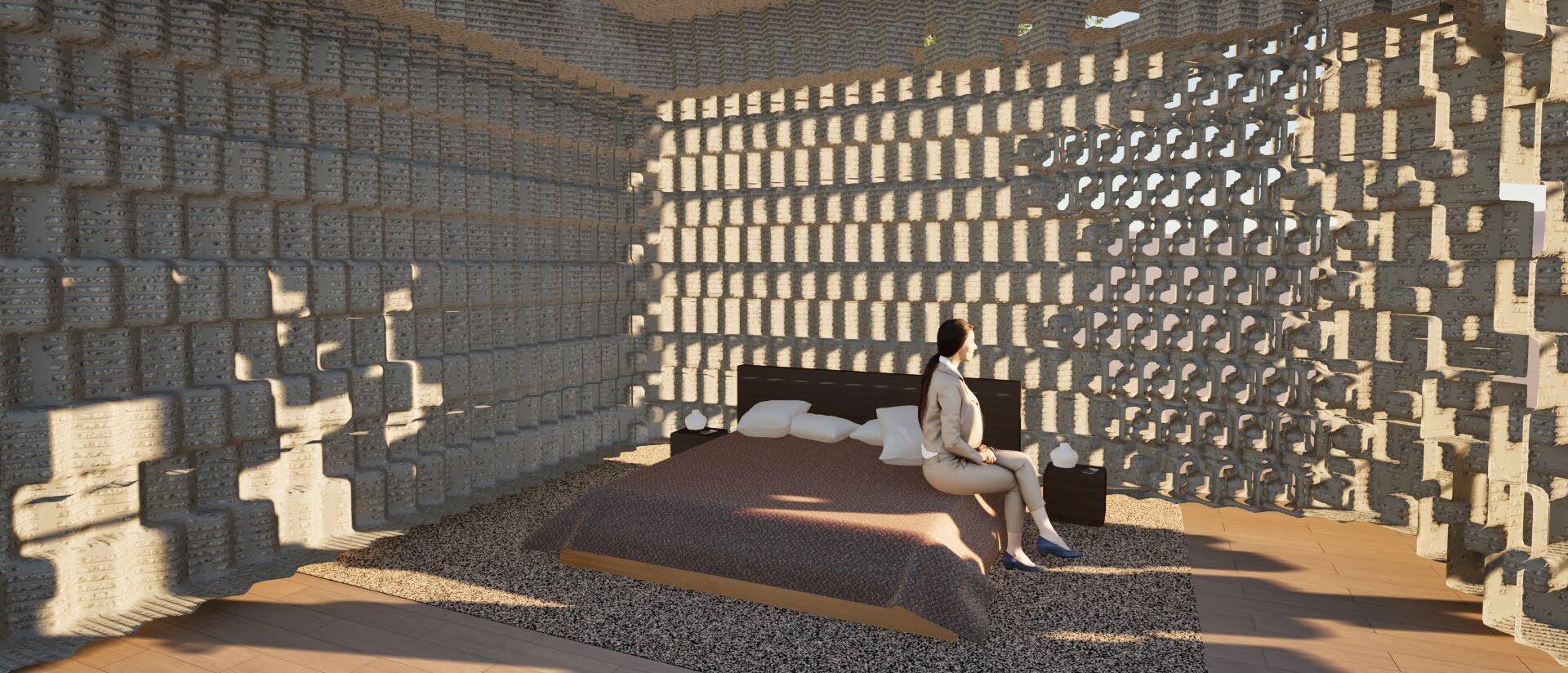
BEDSPACE
The bed is placed towards the back of the unit to emphasize the need for privacy.


EXTERIOR VIEWS
COMMUNAL SPINE
This view shows the heart of the complex. It is meant to portray the feeling of community and closeness among neighbors.


EXTERIOR VIEWS
CREATING NOOKS
This view shows how the units carve out their own front area from the main communal space. Having this hierarchy creates a more usable space for different times and programs.


COMPONENT CREATION ITERATIONS
This project consists of experimenting with different components to create new aggregations. The goal is to find one componenent that works to create a wall, a corner wall system, a ceiling to wall system, and a ceiling to floor system. For my project I started out by obtaining a 1”x1”x1” cube. From there, I cut 1/2” cubes from two opposite corners of the component.

My thought process was to keep my project linear and reuse the original cube shape in new ways on the component. Along with that, I wanted to try and create something nontraditional with the components. That led to turning the cubes diagonally and attaching them to each other by using the indents on the corners. this created a very good connection point that not only
looked interesting but made the project work better structurally. The physical modeling of these components was done using foam. That allowed for a lot of experimentation. The digital models were created on Rhino using Grashopper and Wasp. Using these digital tools allowed for fast creation and ease of modeling.


Cut down the material to a 1”x1”x1” component
Cut 1/2” cubes out of 2 opposite Attach 2 separate components by fitting the positive extrusion into the negative
Start adding more components to each other

For wall creation, start stacking layers of components and make sure to stagger each layer 1/4” back and then 1/4” forward
AGGREGATIONS
CONNECTIONS
Putting the components into the required aggregations was a fascinating task. The original wall aggregation I ended up with had components turned 45° with the indents interlocking. I then discoverd that shifting the wall aggregations layer by layer created an interesting visual appeal. Continuing with this specific design led to some interesting connection pieces on the

corners of two walls as well as on the floor and ceiling. I then discovered that there would need to be a slab system for the flooring and ceiling in order for the components to work correctly. Having all of these components work together to create different pieces of buildings was a very fun and creative process.
Rotate 90° Rotate 90°


Two walls are needed to create a oner system. Rotate one of the walls 90° clockwise and connect the end of that wall to the front of the other one as shown

One wall and multiple individual components are needed to create a wall to ceiling system. To create the ceiling, have singular layers ready and start connecting the peices together by connecting them to each others sides to create a flat surface. Attach the ceiling on top of the wall as a slab system making sure to line up the cubes from the ceiling to the wall.


One wall and multiple individual components are needed to create a wall to floor system. To create the flooring, have singular layers ready and start connecting the peices together by connecting them to each others sides to create a flat surface. Attach the wall on top of the floor as a slab system, making sure to line up the cubes from the floor to the wall.

AGGREGATIONS
SPATIAL EXPLORATION
After the first iterations of basic connections between walls, ceilings, and floors, we were tasked with looking into spatial exploration. This was acheived using Rhino, Grasshopper, and Wasp. I ran into a few problems during this process, but it ultimately worked out and made the process of repeating patterns very easy.
Use the Floor, wall and corner connection tactics to establish an enclosed room

Use the Floor, wall and ceiling connection tactics to establish a room with two walls a ceiling and a floor


Use the Floor, wall and ceiling connection tactics to establish a multilayered model


GRASSHOPPER WALL
USING GRASSHOPPER TO CREATE SPACES
I had some success when it came to creating space in grasshopper with my component. Based on the rules created, I was able to form a wall in Grasshopper, but I was unable to get the layers to shift back and forth like my orginal wall componenent does. Using this software to create design and space could be benefitial to learn for future production as well as for 3d printed housing.


POROSITIES
CREATION

In order to create interest and allow for light, porosity is needed within the compoennets. Due to the depth of my compoenent, I looked into altering my componenent with different wire frames. This allowed my compoenent to be open and airy, but still complex enough to draw attention. The two porosities I came up with consist of 1/16” and 1/8” volumes to create a frame of the


existing component. What made these varieties even more interesting was the elevations and shadows they created. There are strong dominant shadows on both of the components and that adds interest. In elevation when combined in a gradient form, the wall comes alive due to the different sizing and layers perceived within the shapes.


POROSITY IN ROOMS
EXPLORATION
For this portion of the project, we each looked into how our porsoties could be used in rooms. To explore this, we used a base floorplan of a room and moved porosities around to get different results. I personally liked the idea of doing a gradient on my walls to continue the flow of the project. This led to easy transitions and intersting lighting in different areas.


SUNLIGHT
High porosities are scattered to reflect sun patterns

On the E. illinois Ave site, there is room for multiple housing units and that is why I selected this site. This condition allowed for the development of multifamily hosuing and a site for community. Based on site conditions, I put four 1 bedroom housing units on the site. Once porosities were explored, I incorporated them into site design by having higher porosities at the

PROGRAMMING

Areas are located based on hierarchy while connecting WIND
CIRCULATION
HOUSING
southern and northern facing walls and kept the eastern and western walls decently solid. This helps with filtering light depending on the specific program. I broke the site into three main parts: Circulation, Housing, & Community. I wanted all 3 areas to be connected but also separate. In Dallas Texas, some parts of the year are very humid, so to combat that, dogtrot style houses
COMMUNITY

PATTERNS
Wind comes from the S or SE which affects orientation

emerged as a typology. I took inspiration from this typology and placed my two units together to create a breezeway between the two. To make this concept even more benefitial, I orientated each of the units from NW to SE since that is typically where the wind flows in this area.
SITE

SITE PLAN


Housing is central to this site in order to show hierarchy. The communal spaces to the south house a big community garden along with a fire pit for socialization. Otehr community gardens are placed along teh paths to the ommunity area or even in the center aisle between units. The parking lot is placed to allow for ease of movement among the site.


These units programs consist of 1 bedroom, a living area, 1bathroom, a kitchen, and a patio. I configurd this by simplifying my component to a square with four parts. I then split this evenly for the kitchen, living area, bedroom, and patio. But to create different levels of scale, the bathroom fits between the kitchen and bedroom. This allows for plumbing to be close together
together. The main living space that includes the kitchen, living room, and patio are all open to each other. Since the unit is about 768 sq ft, having an open concep feel is a must. The bedroom is tucked away in the corner to provide privacy and solitude for the users. As for the orientation of the units, the public spaces are towards the central aisle which is acommunal space. The
kitchen is adjacent to the living space and follows the NW to SE direction to allow air flow through the space. This helps with ventilation but higher porosities are also placed on the northern and southen walls to help with the ventilation as well. The bedroom and bathroom are more private but they still need access to light. To solve that, a medium porosity was added to
these spaces so that light could get in but it still felt private. The patios are also semi communal and semi private. Each unit has their own patio, but they are open to the main aisle. This allows fo socialization but also permits solitude.


PERSPECTIVES
HOW LIGHT AFFECTS A SPACE
This exploration of porosities in the built environement showed me alot about the importance of spatial planning. Each space has different limitations and needs and there are many solutions to achieve these things. In the first perspective, I focused on the journey to the bedroom. I wanted the room to be tucked away, but since it is a one bedroom unit, there could still be
some visibility. The light plays into this space by giving little peices but it is not totally open to the public eye as other spaces are. The second perspective explores the main living room. This room is meant to get the most light and it is achieved by including components with high porosities. Depending on the date and time, the shadows in this space become playful. In the
third perspective, I looked at the lighting in the kitchen. I wanted ample light, but not too much. Medium porosities were used in this room to achieve this. In the fourth persective, I looked at the patio. the main goal of looking at this was to see the light hitting the different types of components. The pieces become much more elegant when the light hist them and is much more
when the light hits them and is much more dramatice overall. From the outside these components look translucent, but really the interior spaces inside have enough privacy for housing.


POTENTIAL FOR VERTICALITY
The housing created could be stacked to connect to my component even more. I started exploring this concept to see if it would work on the site and to see what kind of environment would come of this change. The same floorplans and schemes would be used, just stacked up to create another level of living. This also brings up the question of multiple
bedrooms in one unit. By exploring this, I got to look at the multiple ways I could go about planning this site. There are multiple solutions that would work to create a positive space for multifamily housing.


SECTION OF VERTICALITY
EXPLORATION
This Section shows the livability of two spaces connecting vertically. Entrances would be in the same area except the 2nd story entrance would be off of their front patio since the floor is shifted 180°.


POTENTIAL 2-STORY SECTION
