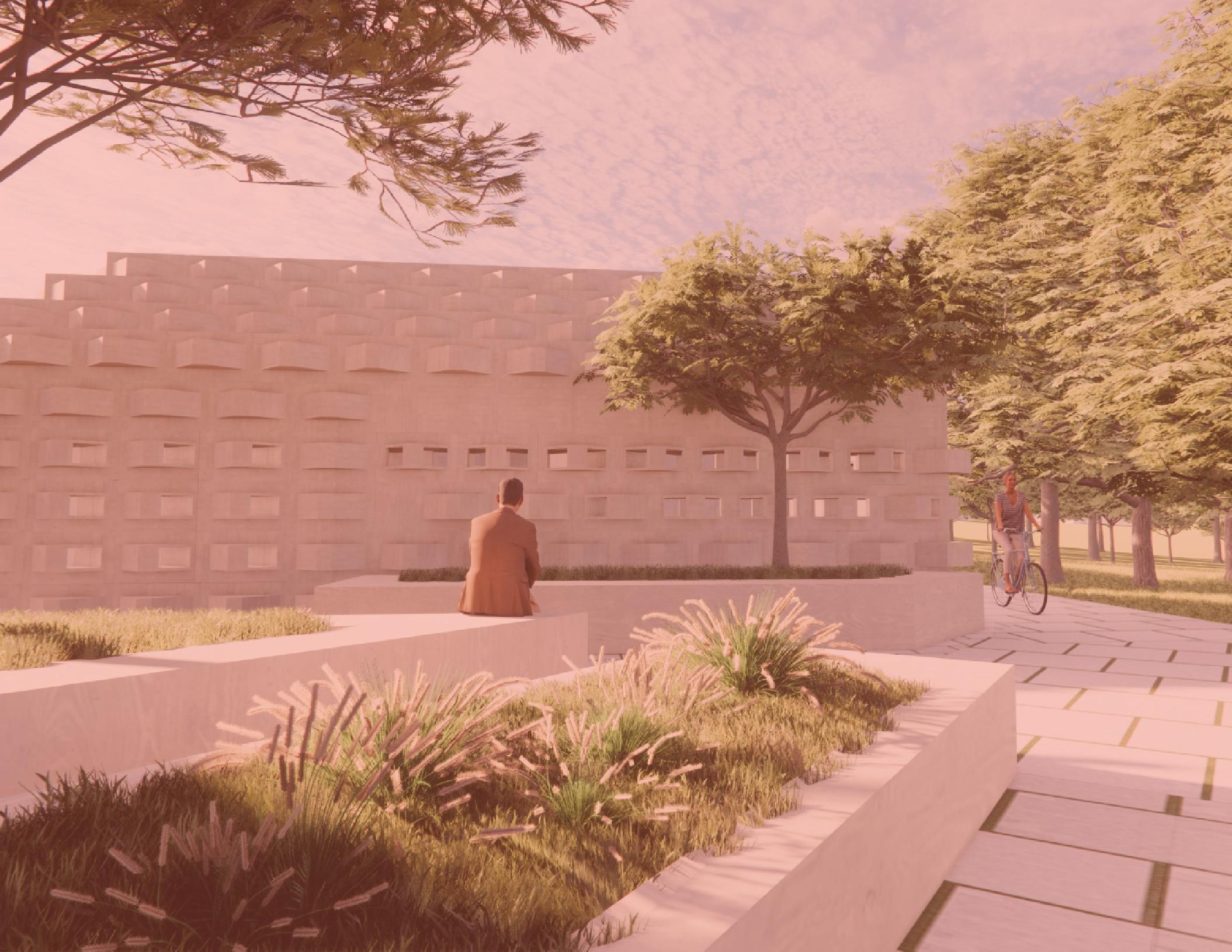

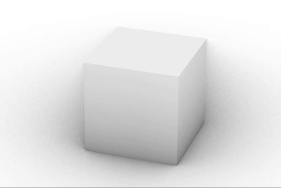
Revisiting my preliminary component, the biggest changes made when designing my new component chamfering the edges and adding protrusion on specific edges. The first major move was made to create a better face-to-face connection at the wall faces. Despite the original component meeting at a face, the fact that it lacked this type of meeting at the interior/exterior
plane led to the formation of gaps and misalignments. The chamfered edges also allowed for a smoother extrusion and acted as a safer, more welcoming component to interact with. The second major move, adding the edge protrusion, was done partly due to the need to fill the gaps in the planar condition as well. But this major change also came about when thinking about
connections. Despite this move now limiting the way the component aggregates across three dimensions, it allows for more solid face connections and plays a vital roll in preventing thermal bridging and the formation of a wall assembly.
REGIONAL SCALE
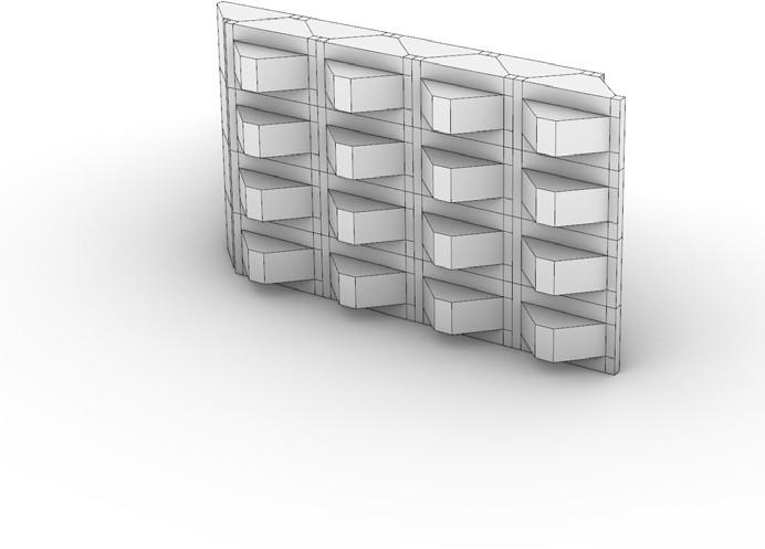
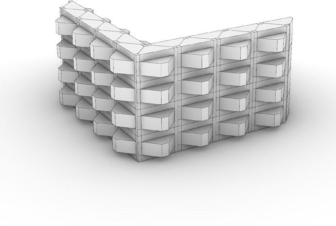
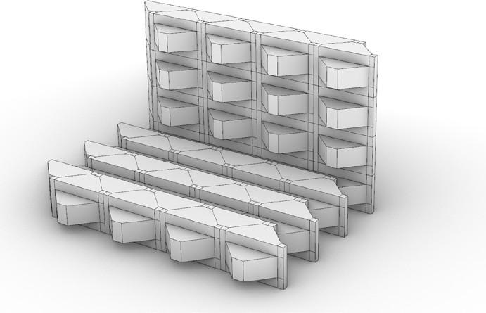
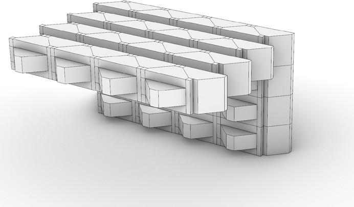
Above are examples of the final investigation of assembly types through digital exploration. These types in order, left to right, are wall, wall-to-wall, wallto floor, and wall-to-cieling. This investigation was meant to provoke thoughts about connections and spatial qualities of the module in combonitation with its repitition across various planes. Despite
succeeding in all 4 tests, I decided moving forward that I will refrain from using my component in the floor or cieling condition. This is not to say they will not work in these conditions because each component assembly shown above could be used as a subfloor and acts as EMP chases. But for the purposes of this project I narrowed my component use to walls and roofs.
FINAL COMPOSITE ASSEMBLIES
REGIONAL SCALE
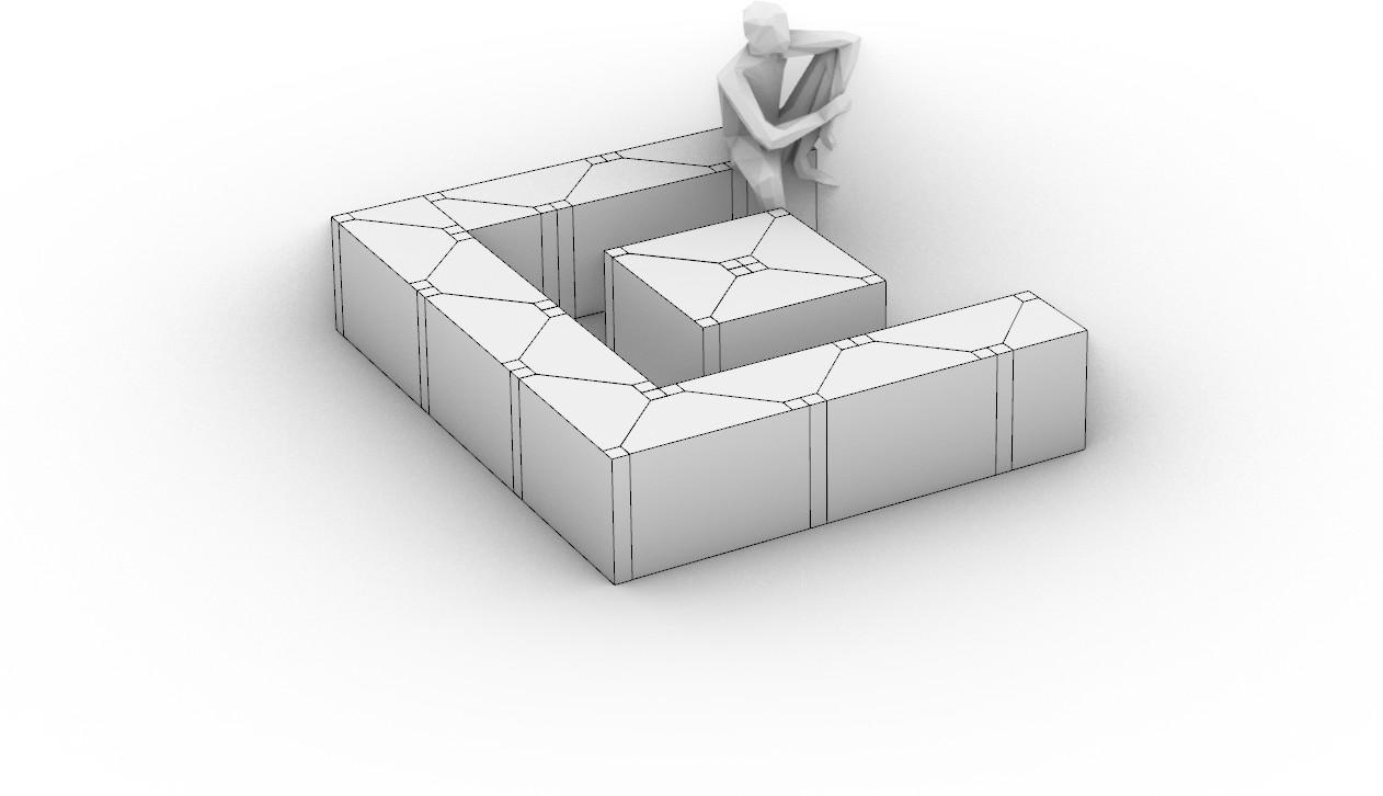
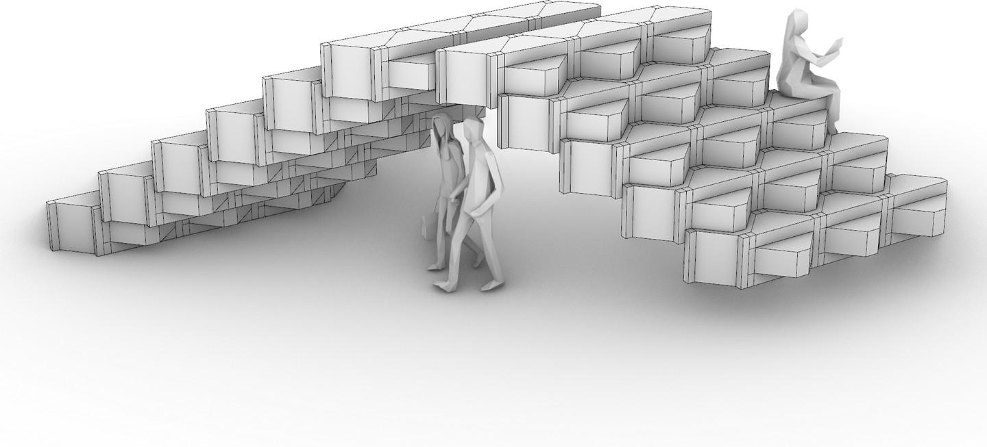
Looking at the final assemblies, I wanted to shift my focus on the potentiallity of the unit outside the microhousing and room structure. inspired by my goals to achieve a truly universal component, I looked at various aggregation methods and build-ups using the final component. Pictured above on the left is a standard build out of a conversation pit with level
coffee table using my component in conjunction with half and quarter blocks of the final component. On the right is a more unconventional structure of an interactive instilation that can be walk through or on. By looking at varying levels of scale and maintaining the ethos of the discreete, this study opened up the possibilities available for my discrete unit.
FINAL WALL STUDY
REGIONAL SCALE
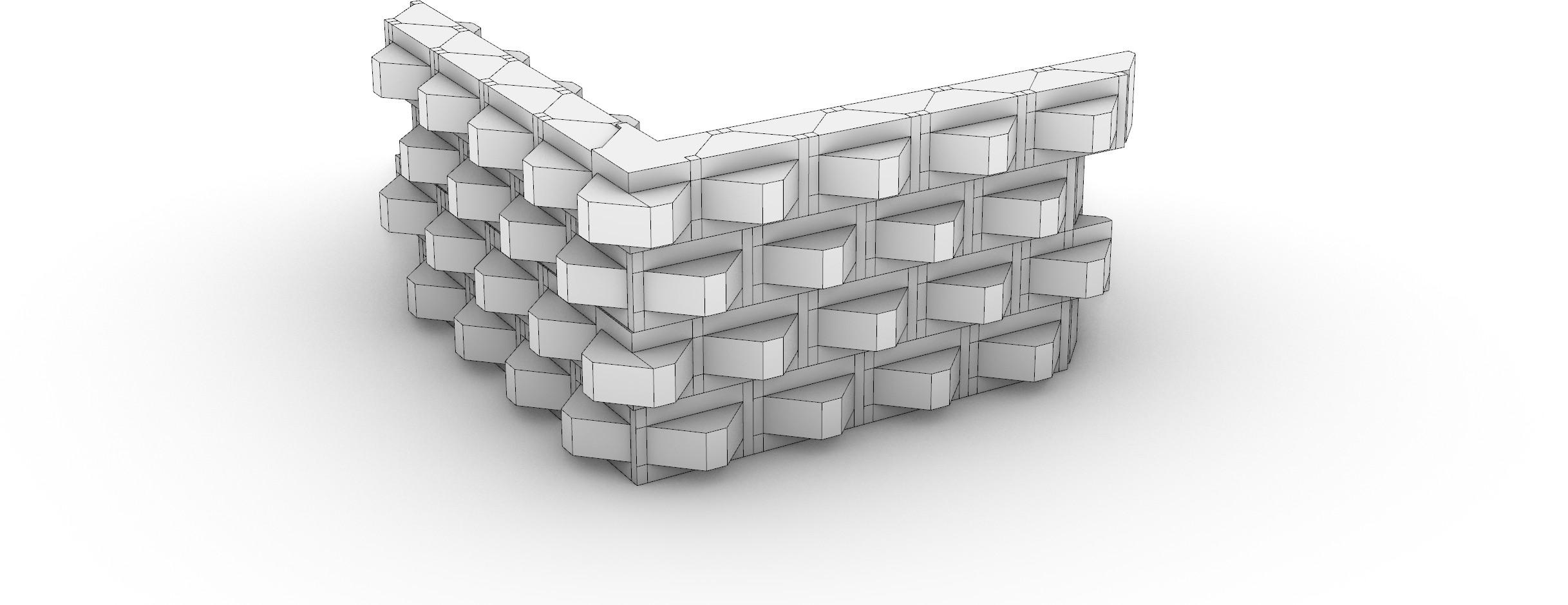
Moving forward from my original microhousing design and wall studies, I wanted to test how a running bond might come togthere in a composite wall assembly, despite requring a new component be made at the cornere to match the wall lengths on either end, the test was succsessful as allowing for a running bond to happen gave more variability in the assembly and broke
up some of the horizontality that plagued the original units facade structure. Also, by creating a new component, we can start to add to a catalog of similar components that evolve out of the final components geometry.

FINAL POROSITY COMPONENTS
LOCAL SCALE
For my final set of components utilizing porosity, not only did I aim to incorporate the same percentages and methods from the preliminary component into the final one, but I aslo wanted to reincorporate porosity on varying faces in varying planes and integrate that into the final build up of the microhousing unit. By adjusting porosity based on
daylight access from multiple faces, a language was formed that was informed by used needs, ultimately leading to the formation of a catalog of components that could be easily modified or produced with minor interventions in the fabrication process.
FINAL ROOM
STUDY
LOCAL SCALE
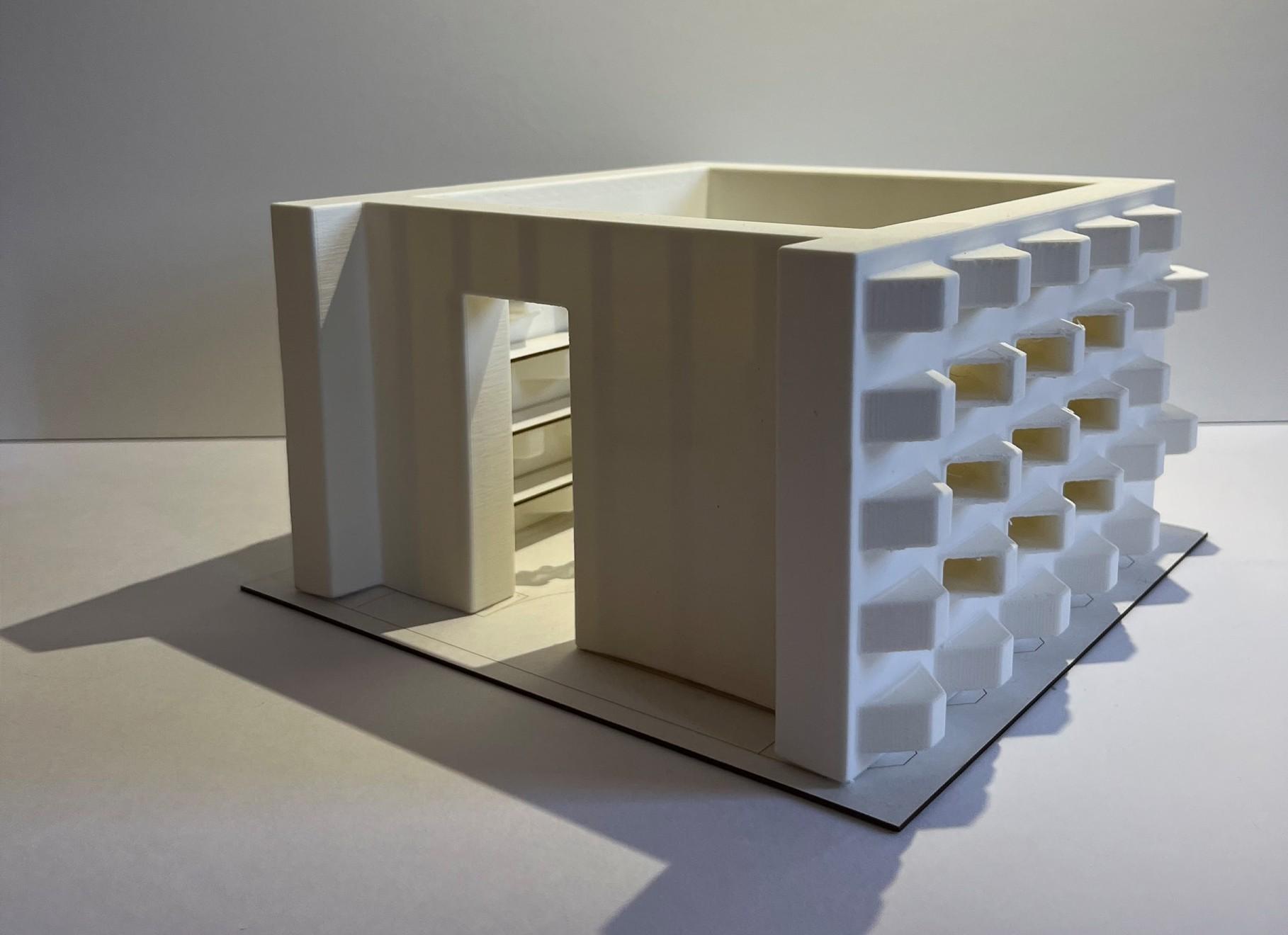
Pictured above is a physical model of a bedroom in a typical microhousing unit on my site. I varied levels and means of perosity in each wall assemblies to form the boundry of a typical 10’X12’ bedroom. the porosity of each unit is organized in horizontal bands with the primary focus being the capabilities of the directional porosity. This study is
the scale of each unit and how light passing through the poros units impact an enclosed space.
Furthermore, I investigated porosity with top lighting. This strategy is used against the back wall over where the bed would sit in the bedroom and despite not working as I had hoped, with the integration of a mirror or a reflective surface on the interior, more light would
be allowed into the space, making a better lit environment without invading the users privacy.
LIVING SYSTEM
INTEGRATION
REGIONAL SCALE
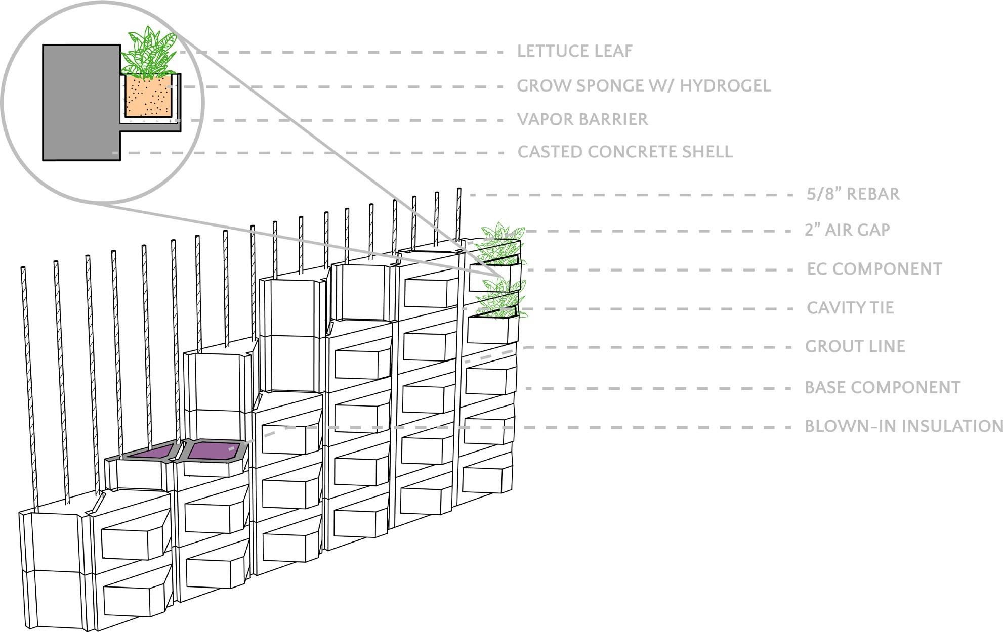
This synthesis of studio and assemblies ideas becomes evident when becomes evident when looking at the structural assembly of each component. By creating making each component its own self contained system that could be easily added or removed from a grid of structural support, it allowed for the addition of components that could house the assemblies work.
Pictured above is an exploded axonometric view of what the wall constructiona and layout of a living system might look like in a unit based off my findings and composition.
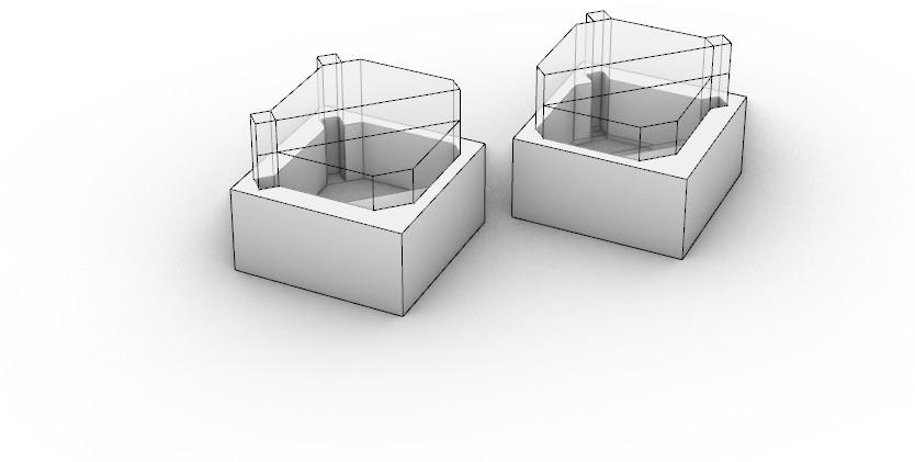
Inspired by the work of Miguel Fisac and his precasted components, I aimed to take a similar route when producing the final component presented here. This two part process would involve 3D printing a mold of the deisred component and then casting the component out of concrete. The reason for incorporating 3D printing into the fabrication equation is so that finer
tuned adjustments can be made to components dealing with porosity or living systems. Being able to coordinate openings and chamfers precisely through software and accurately printing a mold that will be within a low tolerance of error will allow for a stronger integrated and performing system of components. Additionally, I decided to cast the components
as opposed to 3D printing them to ensure the overhang on the component wouldn’t collapse atop the printbed. While it could have been potentailly possible with the construction of a shelf to support the overhang, I sought out this method for its accuracy and easy means to variability.
DISCRETE DEVELOPMENTS
HOUSING SCALE
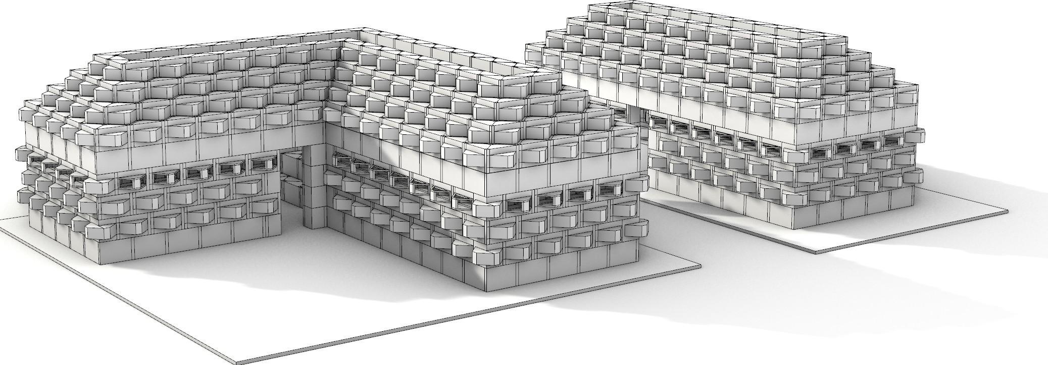
Moving into the final stages, my goals for this project in terms of housing needs was to achieve better density and create a more visually appealing unit. I took inspiration from previous discrete constructions and decided the best course of action would be to break up sections of the facade with running bonds and add another unit type to provide more opportunity
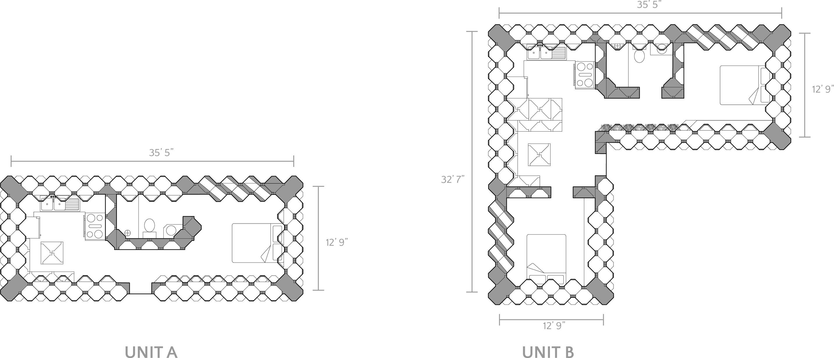
and variability on the site. Both units meet the micro housing requirement with the single person unit (Unit A) measuring shy of 400 sf. and the single family unit (Unit B) coming in at approximately 600 sf.. Both units implement built-in’s, porosity, and living systems based on the previous studies. Each units porosity is adjusted based on site conditions and both maintain utilization of
the component from the wall through to the roof level. A variety of subunits are used to ensure smooth connections. Overall, the microhouses here are representative of an emalgimation of ideas about disretization responding to human needs and programs based on my interpretation of discretization.
Floor Plans
FINAl SITE
DESIGN
SITE SCALE
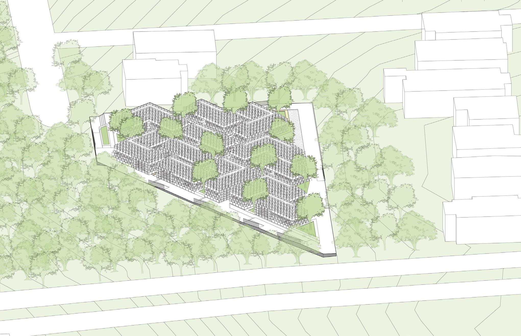
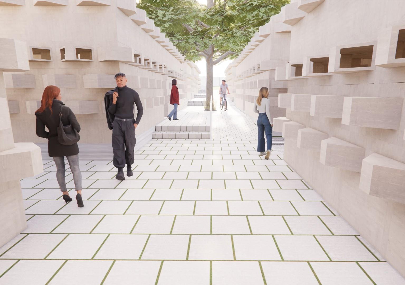
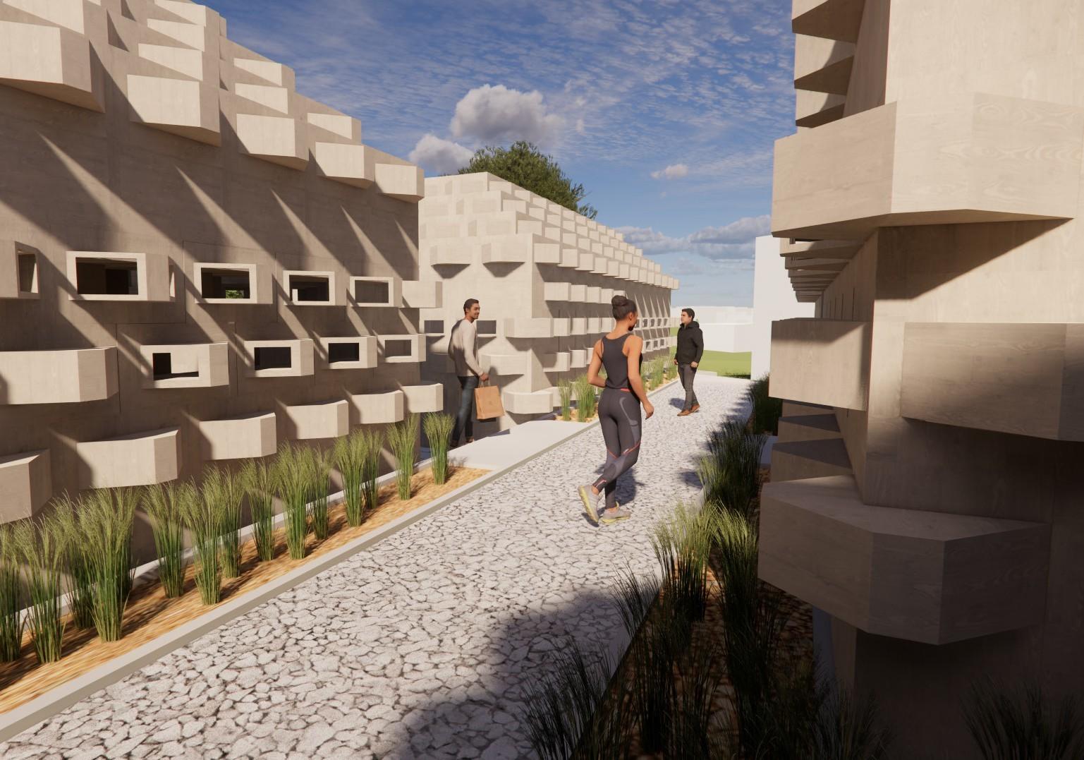
Continuing with the use of the E. Illinois site with a new focus on density, I sought to fit each unit within a diagonal grid to maximize both the units and public space on site. My main strategy for allowing there to be 12 units on this site was providing a major pathway through and around the site while connecting each unit through smaller pathways. This division
of microhouses allowed for the formation of pocket parks and a gradient of public and private spaces that provided ample space for a variety of needs. It was also important to keep the level change on site to break up the linearity of the units while maintaining strong datum lines across. Overall, this site design came about as part of a process to utilize an otherwise
negelected site while maintaining a connection to the surrounding community and allowing for the maximum achievable density

Longitudal Site Section
Exterior Render of Major
Connecting Pathway
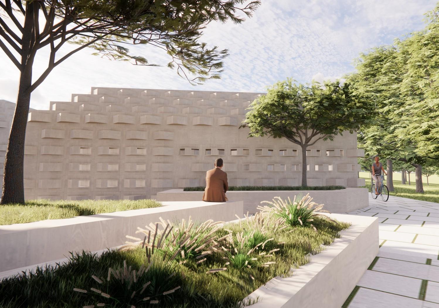
Exterior Render from Site Approach Looking at Unit
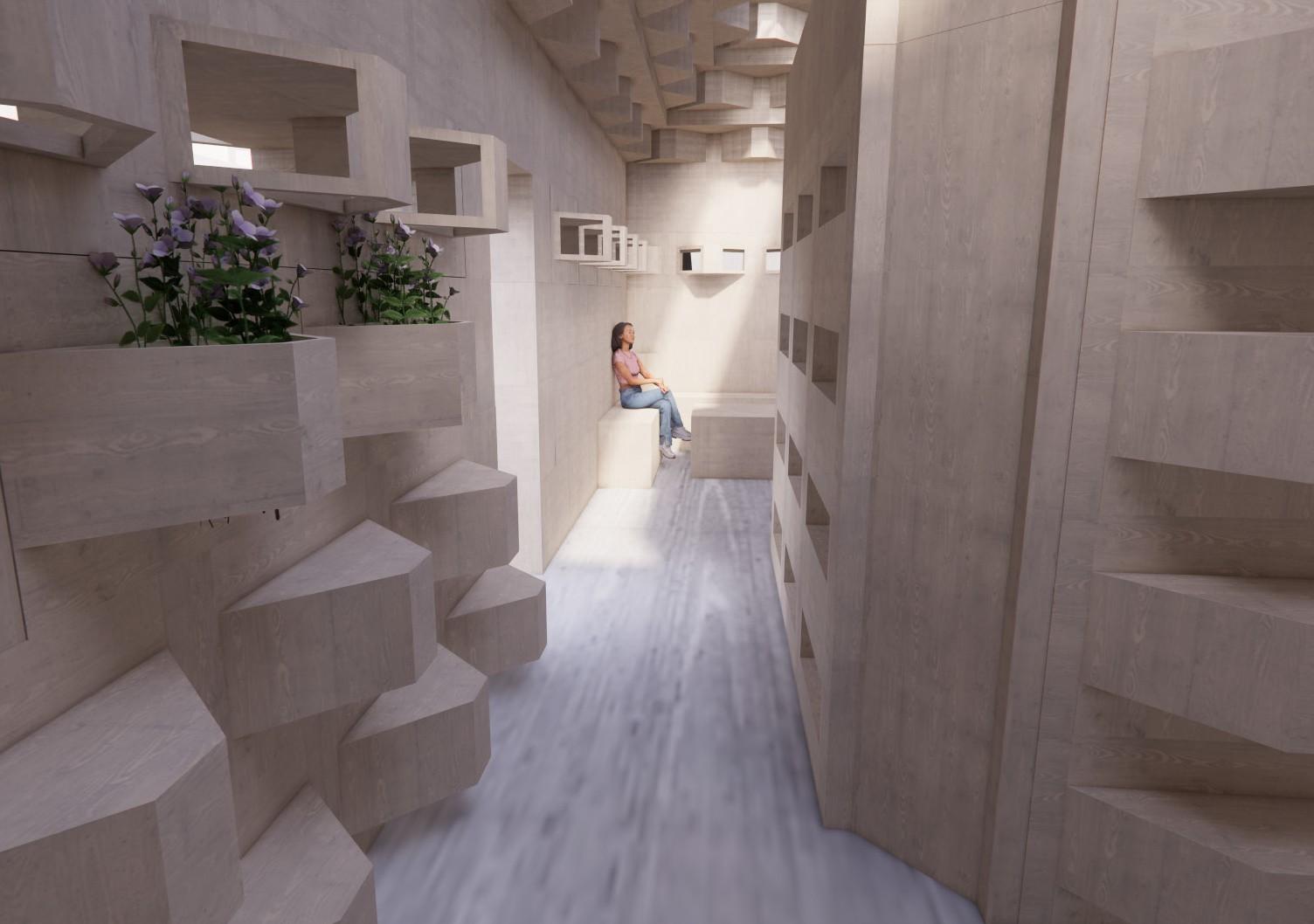
Interioir Render from Bedroom looking at Kitchen/Living (Unit A)
