DIGITAL FABRICATION TOOLS & PROCESSES

COMPONENT & ASSEMBLY
2 ASSEMBLY & SPACE
Vase Printing: Pg. 6 -7
Printing with Infill: Pg. 8 -9
Infill Exploration: Pg. 10 -11
Gradients: Pg. 6 -7
Assembly: Pg. 16 - 17
Operable Louvers: Pg. 18 -asdfasdfadsf


Vase Printing: Pg. 6 -7
Printing with Infill: Pg. 8 -9
Infill Exploration: Pg. 10 -11
Gradients: Pg. 6 -7
Assembly: Pg. 16 - 17
Operable Louvers: Pg. 18 -asdfasdfadsf


Andrew Halpin


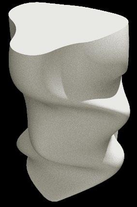
Our first 3D print was making a vase starting with arrayed circles in Rhino. After lofting the curves, and capping the surface. The file was saved as a .STL file. Taking the file into Bamboo, the spiral vase mode was turned on.
Once printed there where a few spots where delamination occurred. This occurred where the angles from horizontal where too acute.

1_ Detail of “delamination” in PrusaSlicer
2_Photo of “delamination” in final print
3_ Diagram of acute angles

The angle at the base was too acute and led to delamintation. If you look closely enough in the preview display of PrusaSlicer you can see the separation before you print.
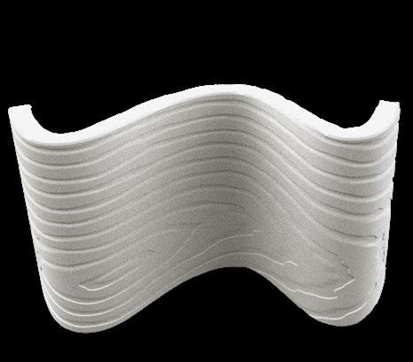


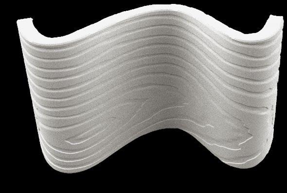
In this exercise we created curved wall shapes in Rhino for 3D printing. I applied a displacement texture to the surface of the wall looking for how it would turn out in a 3D print. I applied a wood grain texture and brought it into Prusaslicer. After inspecting the geometry in the program. I sent it to print.
The print came out accurate to what was modeled in Rhino. The displacement did take a lot of time to reload when making minor edits in the print properties of Prusaslicer.


1_ Final print
2_ Final print with “stringing” shown
3_ Diagram of stringing
If stringing is occurring while printing you can try the following.
1) You can try reducing the nozzle temperature by 5 to 10 °C increments, but never reduce the temperature below the manufacturer’s minimum specifications. PLA (180-220 °C)
2) You can reduce the speed of your print. In the case of my print. It looks like the perimeters caused “stringing” so reducing the perimeter speed could have reduced “stringing”
3) You can try cleaning the nozzle. Ask for help if you have never done this.


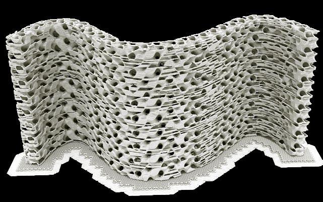
Taking the previous wall, I took off the horizontal and vertical shell of the model to reveal the infill pattern. Choosing the gyroid pattern I set it to 20% density. After testing the infill density, previewing it as low as 5%, I decided the 20% infill density looked the best for printing.
While the 20% infill looked the best before printing because the
pattern was so dense this lead to inconstancy with the final print. Adjusting the cooling and the nozzle temperature could be solutions beyond trying a lower density percentage.

1_ Detail of pattern in Prusa preview
2_ Final print with “stringing” and “melted points” shown
3_ Diagram of fill density %
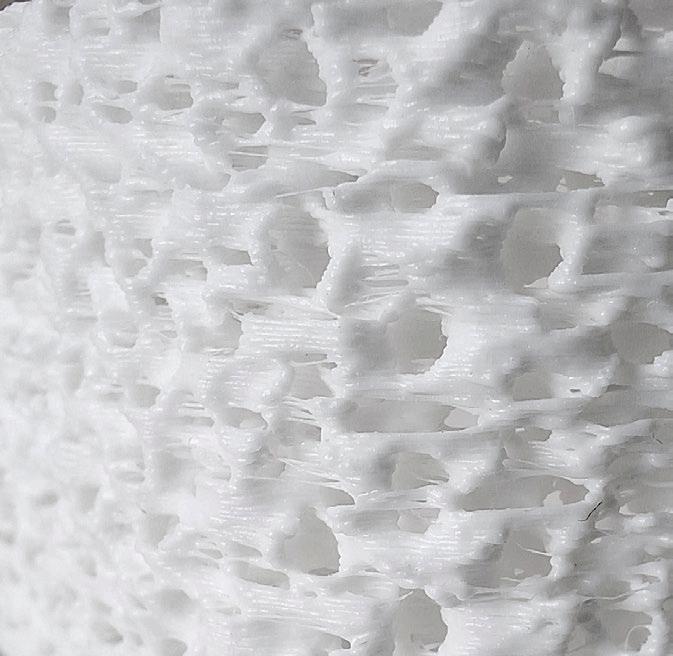
20% Density 5% Density
When printing infill patterns it is important to consider the density before printing. Print times can be shorter with a lower density percentage. With a Higher percentage you get more stability but many things like “stringing” and “melted points” may occur. Try adjusting the infill density before you print.


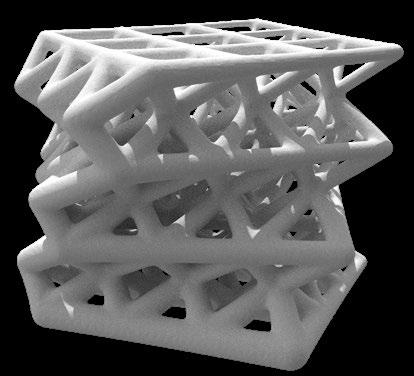
Using grasshopper we created a lattice shell that added thickness using a point attractor, thinner near the point attractor. Half way through the grasshopper script I baked the 2d geometry of the lattice and added a twist to the cube. I reloaded the twisted lattice back into the grasshopper script and added thickness with the point attractor.
I was worried that my structure would be bridging too far so I shrunk the size to 2”x2”x2” but because the cube was too small this lead to several issues due to the thickness of some of the thinnest bridging.
1_ Rhino model
2_ Prusa preview before printing
3_ Printed gradient on Prusa
4_ Alternative print


1_ Detail of pattern in Prusa preview
2_ Final print with “stringing” and “bridging” issues
3_ Diagram of “thin bridging”
Avoid thin bridging
Be careful of thin layers while bridging. In my rhino model the thinnest bridge I has was .826 mm, it contained multiple infill layers in preview, but had issues once printing. There was not enough material for the bridging to hold and caused a gap in the print. In this print it appears that 1mm thickness is the threshold for bridging.

Andrew Halpin


For this exercise we created assembly pieces that would fit together after 3d printing. In order to achieve this before the objects where extruded in Rhino a 0.3 mm offset was created to correct for the extrusion thickness tolerance once the objects are 3d printed with the Prusa.
I choose to create objects that would key into each other and another that would lock together once assembled. One important adjustment made in Prusa was that the print time was going to be over 6 hours. In order to shorten this I scaled the model by 50% in order to cut it down to 1.5 hours, (see figure 1 on page 15) for adjusted model dimensions. You can adjust the scale
of the model while keeping the ratio of the offset distances between the pieces that will key together.
1_ Rhino model
2_ Prusa preview before printing
3_ Printed assembly


1_ Detail of pattern in Prusa preview
2_ Final print with “stringing” and “bridging” issues
The final print came out clean without many hiccups. The tolerance made room for the pieces to fit together nicely. With the 0.3 mm tolerance the pieces where a little bit loose when put together and experimenting with the minimum tolerance of .15mm could create a tighter fit for the keyed pieces to lock together.


For the final assignment I chose to further explore a detail I was exploring in studio. I wanted to model an operable louver system where one would be able to operate a hand crank from the inside of the building and close a louver system. In studio we where exploring ways to have passive heating and cooling and I felt being able to add a third dimension where you could close
the louvers like you would blinds for privacy too. The louvers where angled to let light in the winter and block sun in the summer, passively heating and cooling glazed windows year round.
2_

1_Rhino model of top and bottom position
2_ Baked Grasshopper geometry for perforation
3_ Detail of shadow from perforated louvers

Once bringing the idea into Rhino I began to explore perforating the louvers, allowing for dappled light to enter the building. Using Grasshopper I used a point attractor image to create a wavy pattern comprised of circles. Extruding the curves I placed the geometry over the louvers and used boolean difference to punch holes through the louvers. While successful I was
skeptical of how the perforations would show up in a 3d print. I sent time on the hinges where the louver frame would pivot, making sure to include a 0.3mm offset between parts so it could move freely.


This print I choose to test a small segment of my louver system to see if I could print a hinge connection using the 0.3 mm offset so the pieces would fit together and still rotate. This part of the print went well and fit together well.
The perforations in the print didn’t work out as well. In grasshopper I used a point attractor with an
image sample of a black and white wave pattern in order to create perforations. Unfortunately the range between the lager perforations and smaller ones made it so half of the perforations dint show up in the print. I made an effort to adjust the grasshopper script in order to make larger perforations.
Rhino Model
2_ 3D test print
3_ Hinge connection dimensions

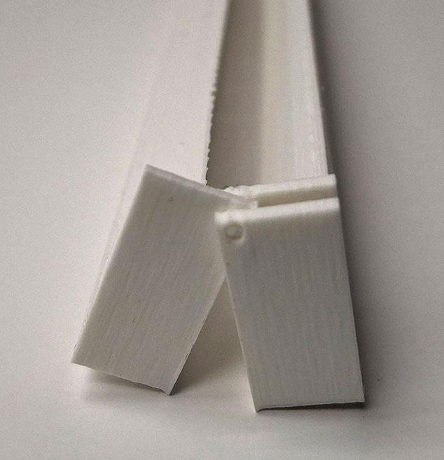

1_Hinge flattened
2_ Hinge at an angle
3_ Detail perforated louvers
If you’re looking to incorporate small perforations try to avoid gaps smaller than 0.85 mm. In this print I tied to incorporate a parametric perforation through my louvers. The print didn’t come out the way I hoped but gave a good indication of the threshold where for perforations show up in a 3D print.


Operable Louvers Test Print 2
Using what I learned from the previous print I changed the perforations in the louvers to 1mm. The smaller perforations where 1mm where the larger ones where about 2mm. After printing it appears that most of the holes where filled in.
The pivoting arm worked well but the support brackets where to long without perpendicular support.
I wasn’t satisfied with this print, specifically the perforations for the louvers so I decided to try and lasercut them for better precision. Rather than make the perforations larger and loosing the scale of what I was trying to design I decided to use a different tool.
1_ Test print
2_ Where bracing could be added
3_ Detail of perforated louvers


Even when making the perforations larger than 1mm it still filled in a lot of the holes. It appears that even using what I learned from the previous print it still didn’t work.
1_ Open angle
2_ 45 degree angle
3_ Closed angle


(1” = 2’-0”)
For the final print I added bracing to my frame in hopes it would make it a bit more sturdy and added notches into the frame so the lasercut louvers would slot into the frame.
The frame printed well without any hiccups and the laser-cut came out good but all the perforations took almost 2 hours to print. This was still
faster than 3D printing the louvers which took nearly 18 hours in my previous print.
The notches I added the .03mm offset from the dimensions of the chipboard (.05”) so the louvers could fit into the frame.
1_ In progress 3D print
2_ Finished 3D print
3_ Laser-cut perforated louvers

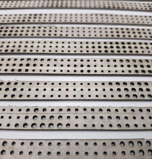

Perpendicular bracing added


Notches added for louvers
For the laser-cut louvers I added an extra 1mm to each side assuming the cut wouldn’t be accurate and was worried the louvers wouldn’t fit into place with the frame.
Unfortunately this was a major miscalculation on my part and that wasn’t enough for the louvers to slot into the frame. I managed to get a couple of the louvers to slot
in but most where completely too short. It does appear that the frame itself wasn’t exactly straight either. Where the louvers could slot in, they wouldn’t fit in anywhere else in the frame
1_ 3D print and laser-cut
2_ Detail of bracing
3_ Detail of slots for louvers


If I could do a 4th iteration I would have laser-cut the louvers with a generous amount of room on either end and hand cut the louvers individually to fit into the frame, seeing how the frame wasn’t spaced the equally at each notch.
This was a good learning experience on the difficulties of trying to 3D print at such a fine level of detail. 3D
printing has its rules, which I tried to follow but working at the 1mm scale gave a lot of room for errors in the print. In the future I will definitely avoid working to the minimum printing dimensions to avoid the inconsistencies I saw in all of my prints.


For this print I attached the louver system to the windows I designed in my studio project and set it at 3 angles to show how the system could open and close.
I ran into quite a few errors printing these as I set up supports to print these and it caused multiple failures. I managed to get one of the prints to work but with the small level of
detail between the louvers I wasn’t able to remove all of the supports without breaking the model. Overall it communicates what I had hoped to show but there is an issue with adding supports to a model this intricate of detail.
1_ Render of 3 louver positions
2_ 45 degree angle louver position
3_


