DIGITAL FABRICATION & PROCESS
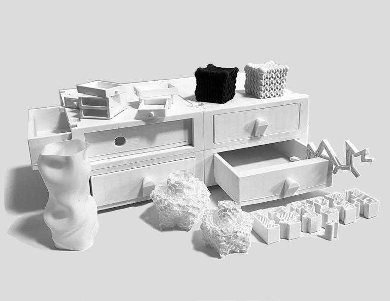

VASE, INFILL, & GRADIENT 1
MODULE 1
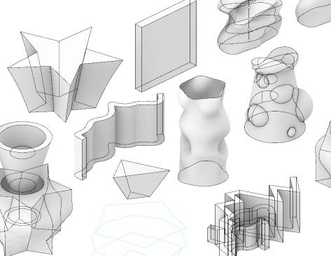
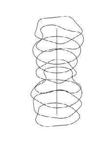
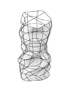
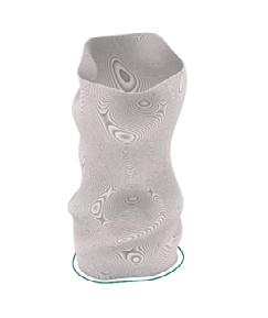
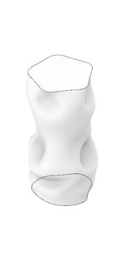
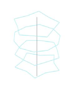
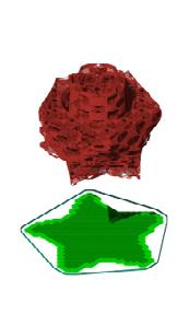
1_ Wireframe of Vase
2_Ghosted View to understand the curvature
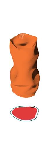
3_ Prusa Exported into Rhino
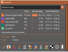
The process of Vase Design was completed through Rhino software by placing polygon tools such as circles, lines, rectangles, or any form that was desired. Once the first layer of design was made, I copied and scaled up the same polygon I made and did some changes to the form.
A helpful tip is to select the polygon tool, once it shows up yellow, type in invert and then hide. This will
make design a little bit easier. When done, type in show and the rest of what was hidden will be displayed again. Repeat this process a few times to a desirable height or scale. Then get a polygon line tool and draw it vertical to the polygon shapes you made. This can be done before and act as support for building up. Type in align and have the line be selected for the shapes to
form around the line at the concentric center. There’s a little ‘record’ button at the bottom of Rhino, click that. It should show up as a darker grey when done. With this on, you then type in loft and select your shapes from bottom up.
If done, ‘enter’ and now you can rotate or reform the vase by clicking on the shapes. ‘Control’ ‘Shift’ and then click could be helpful.
If the design feels completed, type in ‘cap’ and select the lofted structure to enclose the vase. This will help Prusa know on how to print this vase. Export selected object as .obj or .stl for creating a printable version. In Prusa, go to Layers and Perimeter and then have Spiral Vase turned on.
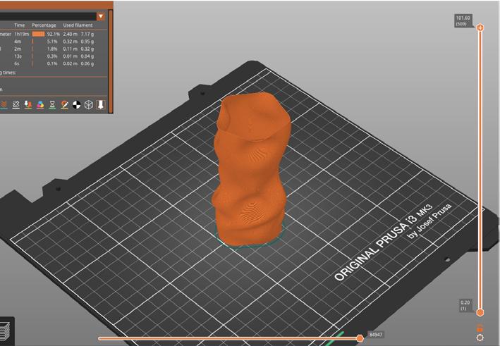
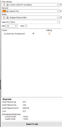
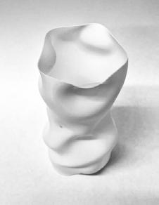
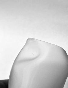
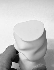
The results of experimenting with my first 3D printing was interesting. I haven’t had much of failures as I found parts that could’ve been made or designed better. One of which is the intention behind designing this vase. With me being a bit behind on classes at the time, just decided to go reasonably crazy.
I found potential issues when I launched this model in Prusa. If parts of the structures showed blue, I moved those forms for printing to make through instead of failing. The only issues I found was the structural integrity of the tip that became flexible and bent. The base of the model was also very steep and hard for cleaning or to keep free of debris.
If I wanted to start over, I would have intended the vase to be designed for holding pencils and pens as well as a structural support to handle the weight of these objects. One of those ways would be having a rounded top to clip on as well as a base that flares out more nicely. I’ve also thought of makning a trash bag version, but that’s still too challenging.

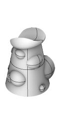
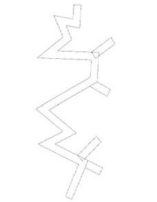
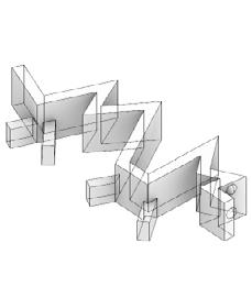
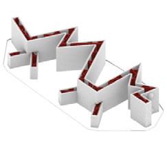
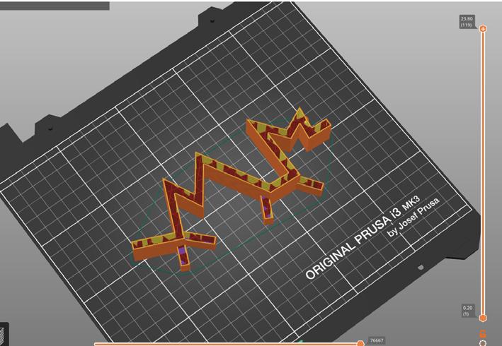
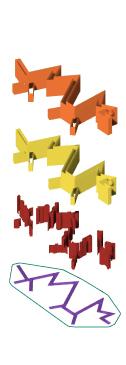
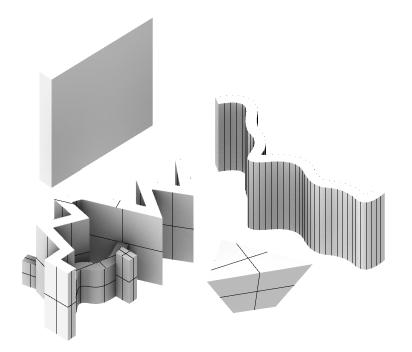
To create walls, use the polygon tool and off set the lines by a desirable number. This can be for architectural models or creating some interesting wall like the lizard creature I’ve created. Then use the line tool to finish the perimeter of the structure. type extrude to create height in the design. Lastly, type extrude to create height in the design. Now, adding boolean union to the walls for eyes,
legs, and anything else that would be cool. I went for the legs and eyes to mimic of what this creature would represent.
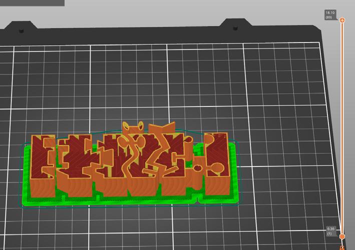
After designing the walls in rhino, export the selected object into Prusa through .stl or .obj. If wanting to see the walls in print, go to Layers and Perimeters and set the solid layers to zero. My infill was stars for this was star shaped.
1_Structure before extruded
2_Structure extruded and boolean union added for the eyes and legs
3_Final structure in Prusa exported to Rhino
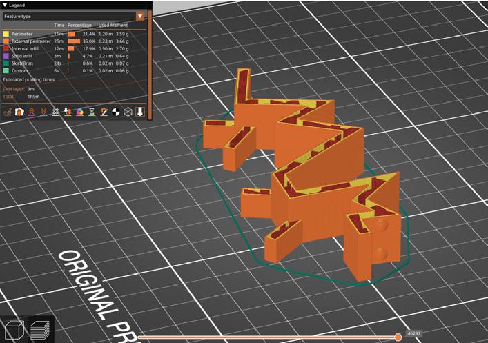
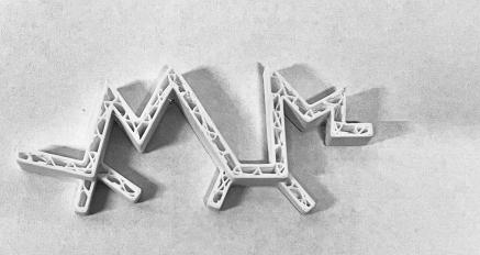
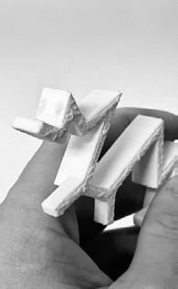
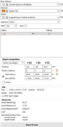
One of the main issues I’ve found with this print is using the wrong G-code file and that could’ve caused the raft layer stick on the base more aggressively. Removing the filaments has been difficult in tight spots such as the interior of acute angles and in the walls. The face has strong tension force while the bent in the larger hump tends to have a failure point. Meaning
the flexibility is weakening the structure. A different infill pattern would’ve been better utilized or increasing the infill size to have better structural integrity. The base of the acute angle’s sharpest point has some deformation due to the challenges that the machine faced.
Overall, the design of this creature has been a fun process from polygon curvature to sharp angles. This lizard could’ve formed my initials or be able to stand on its own. Next time I would definitely experiment more with density, location of the walls, and boolean difference of holes in the walls.
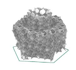
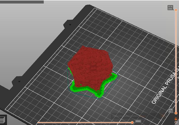
The infill design has been a repeat of the first week Vase project. After lofting and caping the design I’ve created, I decided to use ‘boolean difference’ in cutting the details ontop of the object while experimenting with ‘boolean union’ to add and subtract from the structure. A helpful tip throughout the design in rhino is ‘control’ and ‘shift’ at the same time to select
any edges or line on the structure. This will help click on parts of the structure that other wise wouldn’t have been able to be edited.
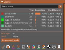
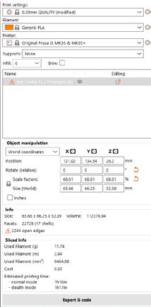
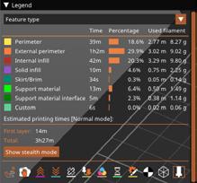
In prusa, I have squished it to meet the one hour mark while modifying the fill density to 6. The fill pattern to 3D honey comb with the length of infill to 2 mm and the max to 10 mm. I’ve also removed the support material genenerated supports and added raft layers. Both solid layers of horizontal shells are zero. along with vertical shells’ perimeter to be zreo too.
This is only for the result of the final print that I’ve created. The first prototype had a higher fill density.
1_Structure before lofted
2_Structure lofted, capped, and using boolean tools
3_Final structure in Prusa exported to Rhino
1_ Diagram, workflow process
2_ Photography, physical model
3_ Mosaic, material properties
4_ Photography sequence
5_ Masterplan strategies
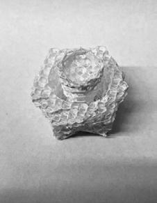
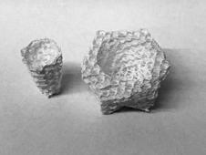
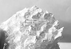
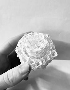
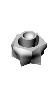
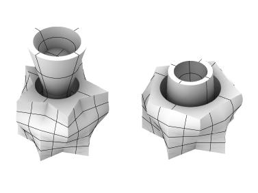
Both of the printed prototypes failed my expectations for the structural integrity of the piece. Although it has been amazing to see the prints come out without any walls, I thought the infill would be stronger than the walls themselves, but that wasn’t the case. Instead, there was more integrity with higher density of infill while the fig 3&4 had better support of the column in the center.
The main difference between two prototypes is the ‘boolean difference’ that cause the first one to be parallel from top of the column to the base with the side walls. The second prototype has the column tapered from a flare base to a skinny top.
The infill density was also too low in which at enough kneading with a nail will break the filaments that are attached together. Nex time I would increase the density of infill while using the second prototype to help with the structural support of the column.
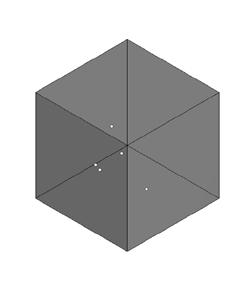
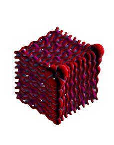
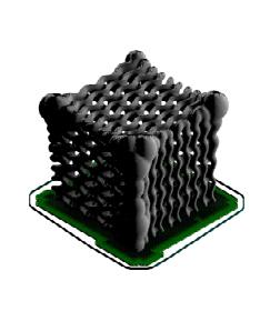
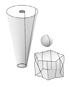
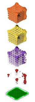
The gradient print was using a grasshopper script by utilizing a box structure in rhino. These lines were given a thickness within the script that got visualized in Rhino. This frame was then used to create a mesh version in Rhino for export as .obj file for Prusa. Page 19 has the examples of the grasshopper script I’ve used to create this gemoetric pattern.
A helpful tip is to unsee the previous visuals that grasshopper gives by right clicking on a script and click on the blindfold person to hide the visual. One of the main focus of this design was utilzing the voxel and smoothness of the surface to get a cleaner look.
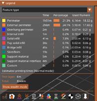
In prusa, I changed the fill density to 5% or less because the structural integrity of this print would already be so strong. I used the aligned rectilinear pattern with the max length of infill anchor set to zero. As usual, there was 3 layers of raft to this print for better results.
1_Cube
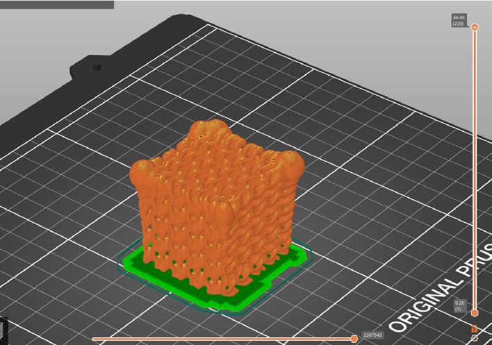
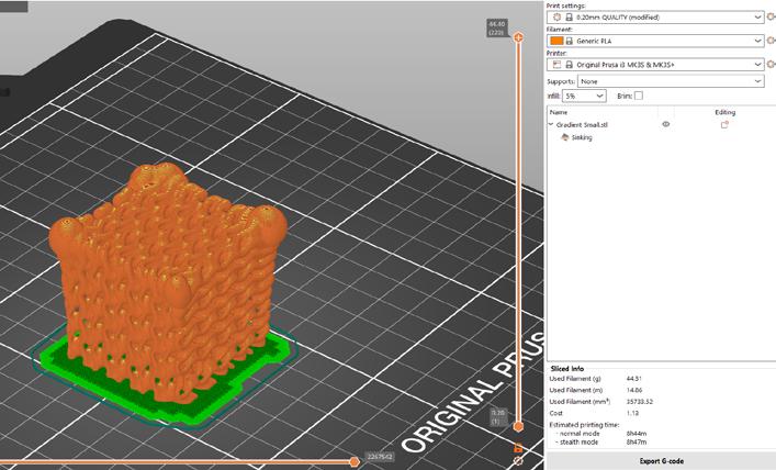
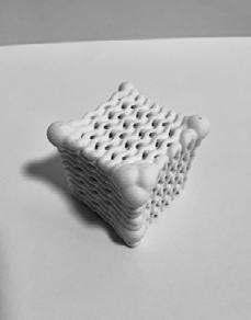
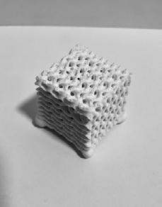
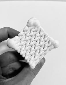
The main issue I had with this piece is time. No matter what I’ve done internally to the structure, time won’t go below 8 1/2 hours for printing a 2”x 2”x 2” structure. It could’ve been the smoothness of the voxels, the thickness of the gyroid pattern or the density. I didn’t do much exploration as I was having issues visualizing in grasshopper.
One of the challenges faced was the ability of printing this structure on the flat surface. A quick way of mitigating that issue is forcibly move the structure below the mat in Prusa for the cube to remain flat during print. Otherwise, the gradient print survive its 8 hours of overnight print and it looks beautiful. Next time I would change the voxel thickness, smoothness and the density of the pattern.


MODULE 2 INTERLOCKING 2
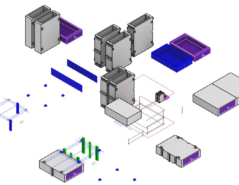
To start off, create a rectangle with thirds or however many divisions through points and ‘divide’. Then with ‘PointsOn’ command, ‘ctrl’ ‘shift’ and then left click over the points that are desirable. Now we can shift and move things around. went and explored polygons, curve, and circles on how they could interlock. Plus ‘BooleanUnion’ or ‘join’ the polygons into their final
shape. On each line in the center of the rectangle, offset each by 0.15 mm or 0.3 mm, depending on how tight they can be printed. Then ‘CurveBoolean’ with the combined regions set to ‘no’. Extrude what resulted of the curve boolean with extrusion being solid. Then seperate each and print!
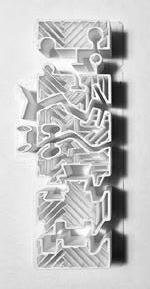
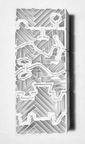

There has definitely been some interesting results from the prints.
I’ve done both 0.15 mm and 0.3 mm and that 0.15 mm works wonderfully. With the 5 iterations, the first is my favorite with the most tightly locked piece while 2 and 5 don’t lock. If i wanted to lock 2 with angled lines, I would double up on opposite ends and inwardly to each other. The pin lock on 3 worked,
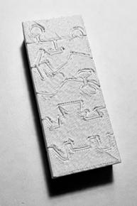
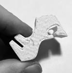


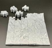


however, another pin on the other end would be great. The issue is the pieces getting lost in both 2 and 3. As for 4, the interlocking shape is fun to work with, yet it takes up space in the piece. Trapeoids are not going to work in my design. Lastly, 5 seems promising for interlocking, yet how can pieces be interlocked in 3D?




WITH INTERLOCKING
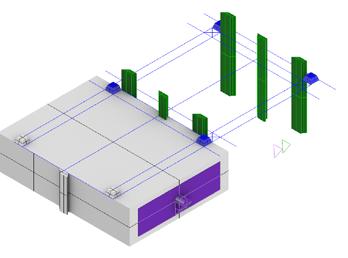
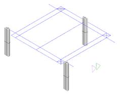
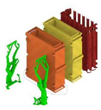
To start off, I started thinking about the intention behind this piece and the parameters of 3D Printer Prusa. I landed on the idea of supporting full length of prisma color pencils and other things that can be stored. One of the things to consider is using less filament and not having to sand down when otherwise can be smooth.
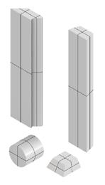
With that said, the container itself had to be printed vertically without raft and that the mechanisms should have the ability to print without supports. Thus, trapezoid came in as the solution for interlocking. I would be nice to lock it more securely, but haven’t found a method yet. Then the drawer had to be printed horizontally due to the base and walls. That means the handle will
need to work with gravity. I’ve started off with a solid box and then experiemented with trim, boolean union and difference as well as offsetting the drawer by 0.5 or even 1 mm for the ability to open and close the drawers with ease.
The footers and trapezoids were offsetted by 0.3 mm to connect more tightly.
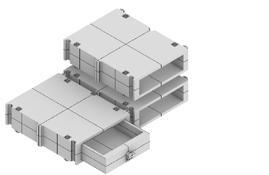
1_ Prototypes for Interlocking
2&3_ Container Prototype with interlocking on side with green for subtraction and addition visualzation
4_ Finalized Idea of how model can be used for vertical printing
5_ Final outcome of printing
6_ Containers being stacked vertically
7_ Final Outcome of print at larger view
8_ Exploration into opening from either side
9_ Exploration into Reaction Diffusion for printing.
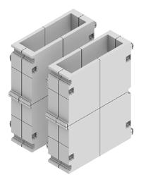
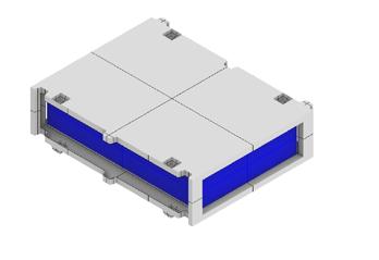
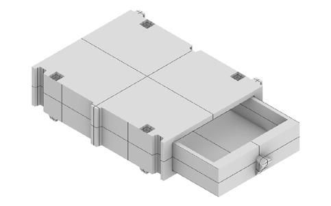
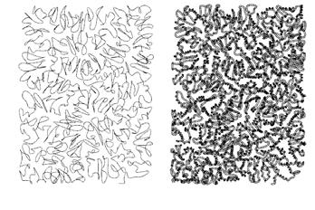
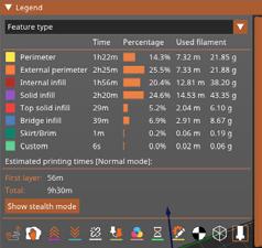
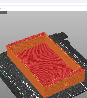
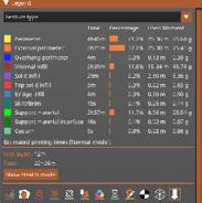
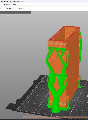
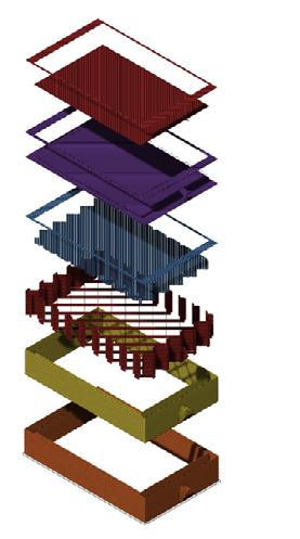
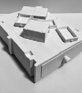
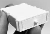
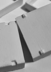
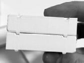
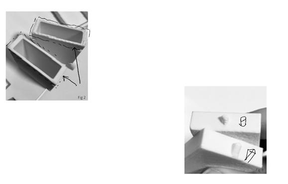
Most of what I’ve said in the design phase has been worked through some iterations of prints and brain thinking of why some can fail or succeed. At 1/4”=1’-0” scale, there was some issues that were bound to happen from small scale to full size. One of the things I didn’t take into full consideration is the difference in gravity of the size when I did my full prints. However, I was able to figure
out on how much smaller the drawers needed to be, the handle, and mechanism of the interlocking design. I’ve also tested on rafting as it can be seen in Fig 2 & 6 of the results.
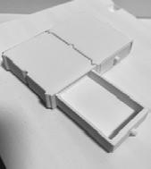
1_ Process Printing compared to Final
2_ Rafted vs on plate
3_ Flat Pyramid interlocking prototypes
4_ Stacking of said Flat Pyramid
5_ Final process prototype with drawers able to fit
6_ sanding down raft layer from initial print
7_ interlocking mechanism as well as drawers
unable to fit to drawers able to fit
8_ Gravity print fixed
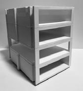
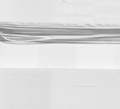


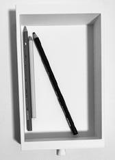
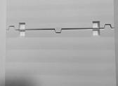

In the final prints, there was new ideas that came about with the design such as Fig 6 side container, however, seeing the containers as objects to hold and adapt to my needs has been fun. In Fig 2, the top shows the filaments being stringy due to the angle not steep enough while the bottom shows the texture from the support used. If sanded, it doesn’t do much for visuals.
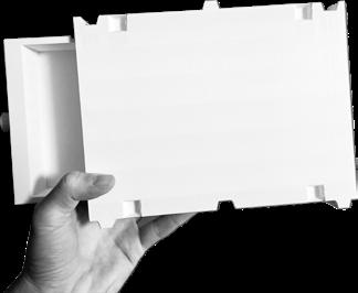
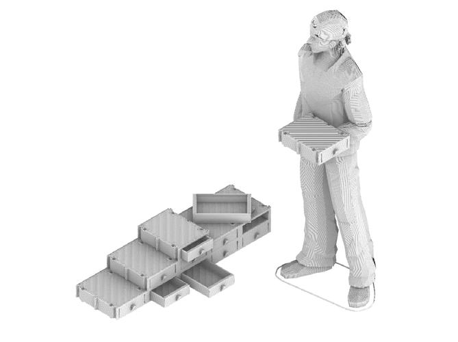
Overall, this project has been a fun experiment in product design and application to my personal life. Currently it supports my monitor with ease as the container is 8”x6”x2” in size. However, the print time was absurdly long ranging from 9 hours for drawers to around 22 hours for containers depending on some modifcations.
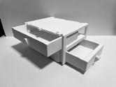
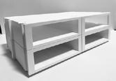
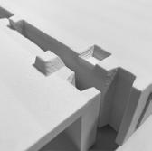
1_ Models stacked vertically
2_ Non-supported vs Supported during vertical print
3_ Color pencils being able to fit in drawer
4_ Interlocking Visual, easy to seperate.
5_ Vertical interlocking
6_ Exploration in side drawer that can work with the typical drawer design.
7_ Another idea of interaction
8_ Close-up of interlocking mechanisms.
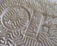
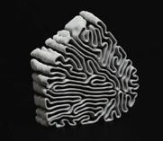
Optional experimentation with adding a parametric design ontop of the containers or the side such as Reaction Diffusion on the right. The challenges are on how to add them to the current interlocking design.
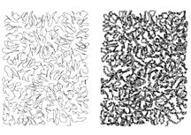
The main issue of this design is that the container doesn’t slide neatly between the columns at either end. A solution to this approach is recessing the inserts into a predetermined direction. The problem associated with this idea is that the inserts essentially works with only one drawer, not the other.
After finishing up the prints, there was some ideas in design that I would love to modify, add, or change completely.
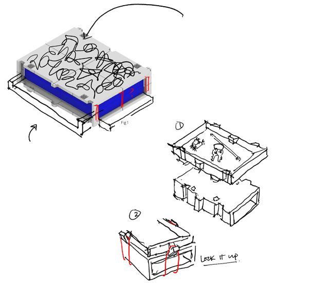
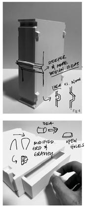
1_ Modifcation for potential further interlocking
2_ Reaction Diffusion Ideas
3_ Drawing of idea to add ontop of design or incorporated for all.
4_ Horiztonal Print of Container
5_ Drawer handle design and other potential considerations
