

Vase Printing
Pg. 6
Infill Printing
Pg. 8
Exposed Infill
Pg. 10
Gradient Infill
Pg. 12
Tolerance Testing
Final Project Pg. 18 Pg. 18

Weeks 1-4 MODULE 1


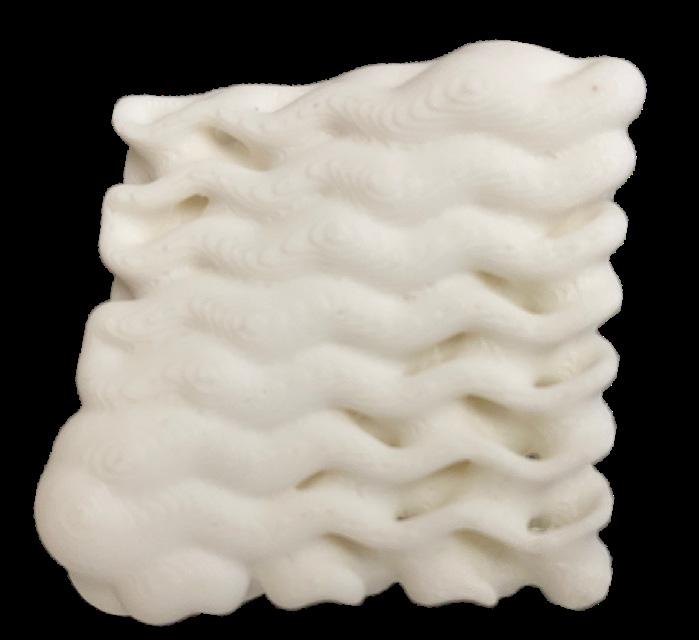
This vase is built with a slightly wrinkled surface to test the abilities of the Bambu printer. The workflow was to first create a curved line to create the outer edge of the vase. Next, the “Revolve” command was used to revolve the curve around a vertical axis to create an open surface in the shape of the vase. Next, the “Waveline Shaper” definition created by Sim Pern
Chong on Grasshopper. This was used to create and edit a ridged surface that was applied to the vase using the “FlowAlongSrf” command. Finally, the “Cap” command was used to turn the vase into a closed polysurface for 3d printing. The print itself took less than an hour and 7.9 grams of filament.

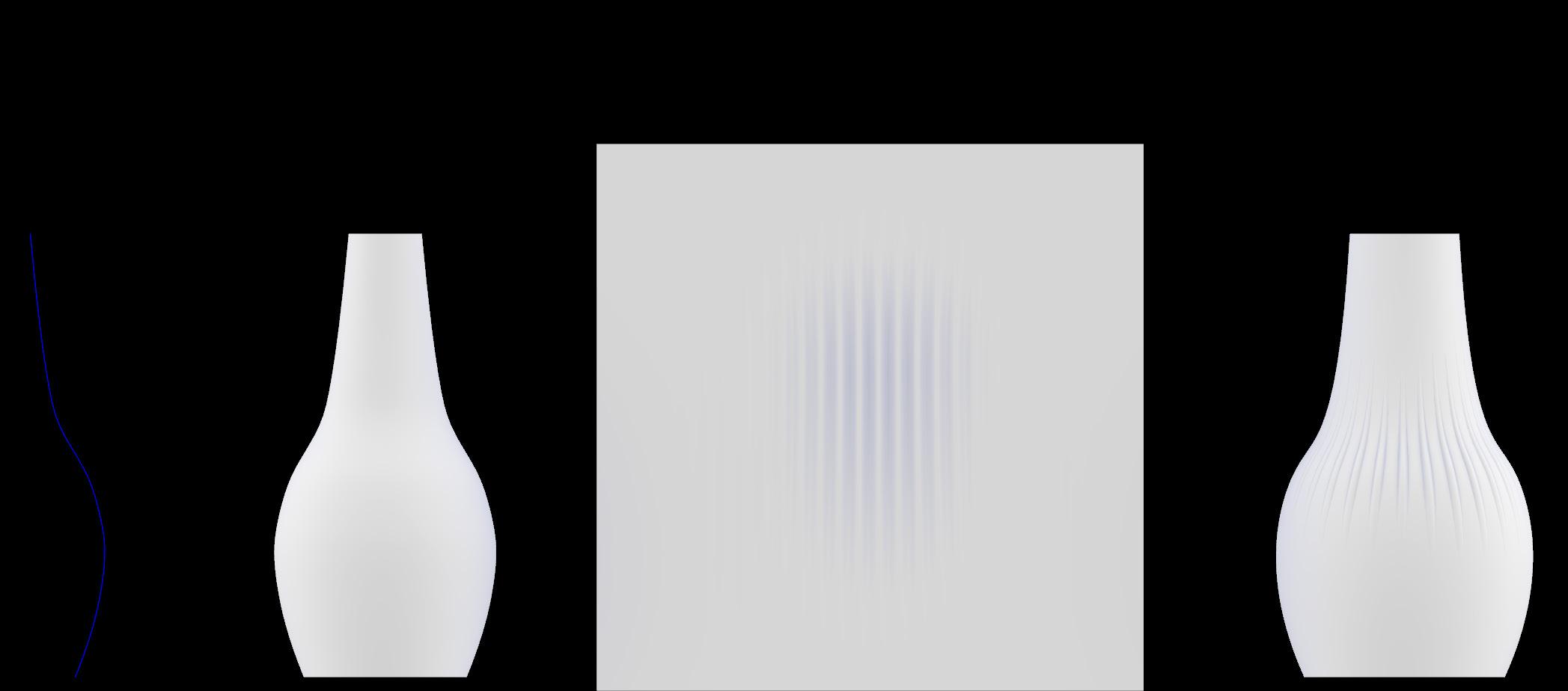
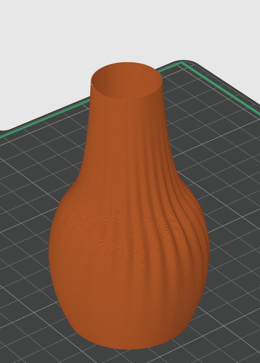

The vase was sliced in the Prusa Software. It was imported as a solid object, but selecting the vase mode in the settings made the vase one single layer. Selecting vase mode changed all other necessary settings such as geting rid of infill and the top face of the vase. The Bambu printer did a great job printing the vase. There were a few tiny dark smudges on the exterior of the vase.

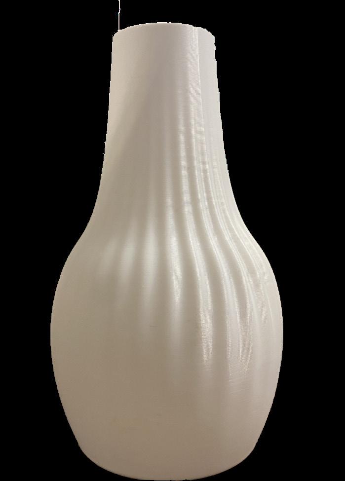
These were likely caused by the PLA temperature getting slightly too high. The vase came out very fragile to squeezing with it being made in a spiral that was only one layer thick. It is important to be careful about the size and geometry of an object when printing in vase mode because the resulting print will be very weak as it has only a one layer thick perimeter.

This project was focused around creating a unique geometry to text infill patterns within. This geometry was created by extruding elipses upward and using “BooleanUnion” to combine them. The geometry was then brought into Prusa Software to slice. The estimated print time was too high because of the scale of the print. To fix this, the print was brought below the build plate.
When sliced this created a new shape that was quicker to print and ignored what was beneath the print bed. Next the top layer of the print was cut off so that the infill was visible. The infill settings were made to be 15% with a gyroid infill pattern. Finally, a raft was added to the geometry shown in green. This helped with first layer adhesion on the older Prusa printer.


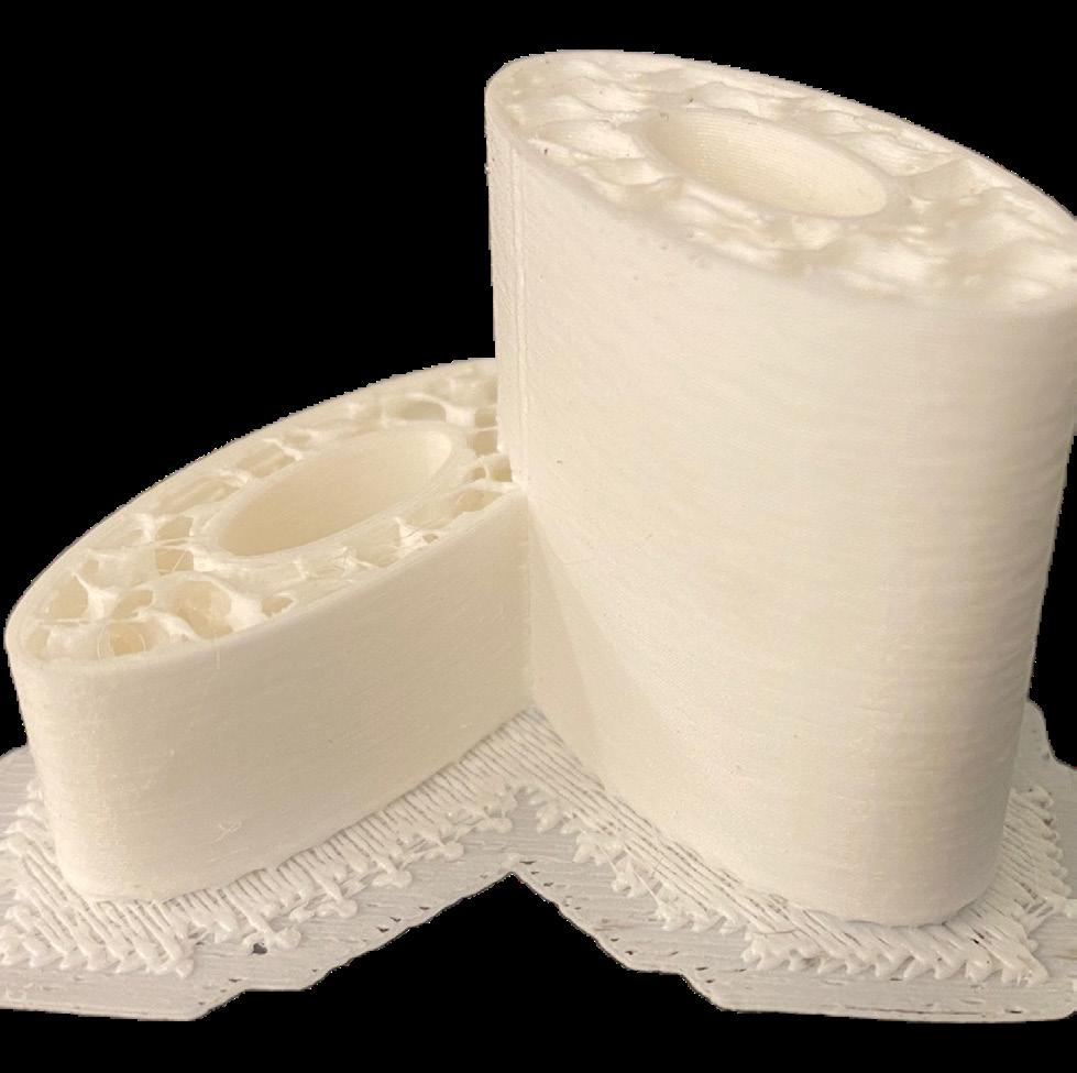

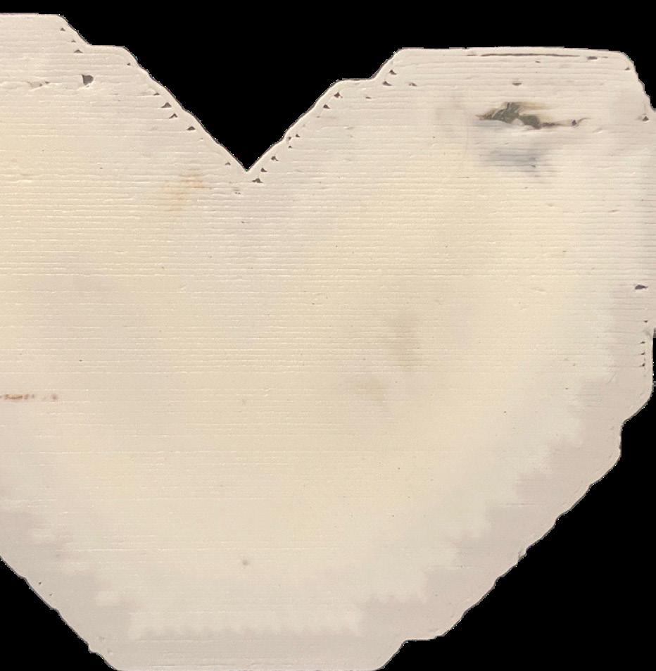
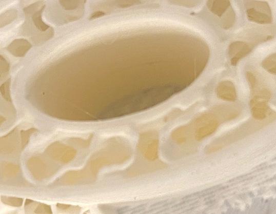
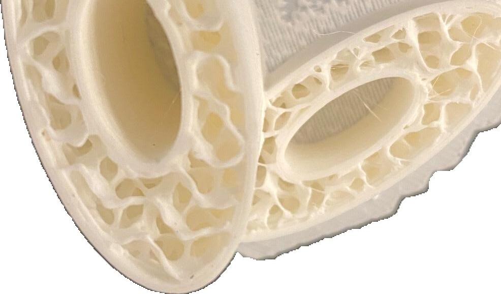
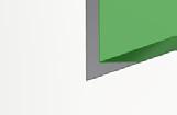
There were a lot of small printing errors with this print. On the left image there is a visible seam along the inner edge of the taller mass. This seam is likely the area where the print began and ended at each layer. The seam could indicate that the print speed slightly too high or the temperature was slightly too high and too much PLA was extruded at each layer.
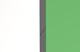
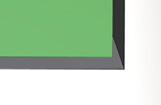
The center image shows strings caused at the end of the print. These were likely caused when the nozzle bridged gaps between infill. The rightmost picture shows problems caused at the first layer. There were issues with layer adhesion espeically in the corner where the PLA pealed off and was printed over. The heat from this process likely caused the discoloration

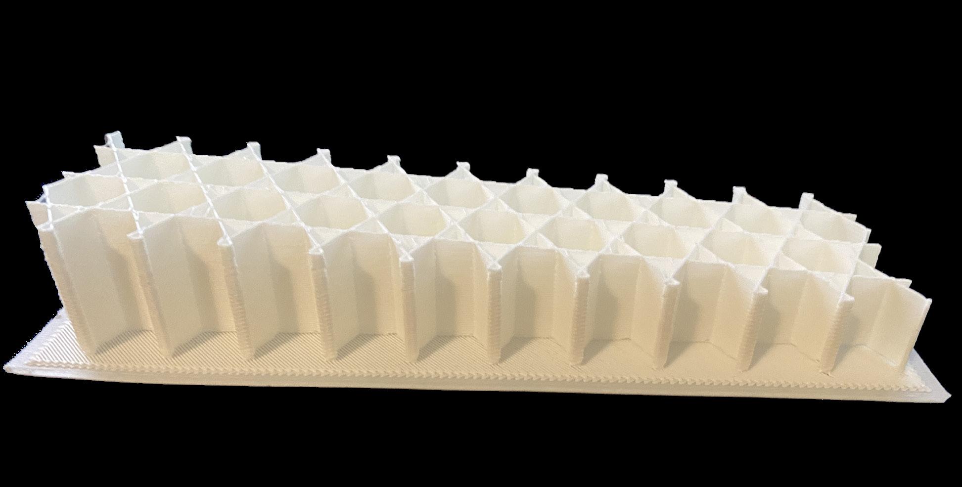
This portion of the module was focused on creating a simple mass and slicing it to only consist of the infill. To do this the vertical and horizontal shells were turned off. The infill settings were turned on to star shapes with 10% fill. This made the star pattern visible but not very dense. The print is strong and stable without walls.


There were a few minor problems with the print. First, the harsh angles from the infill pattern didn’t translate well to the printer. The outer edges weren’t even and caused from the very tight angles of the star and a too high print speed. There were also wobbly lines on the top of the print. These lines were present in slicer, but the bridging was too far and became very stringy.


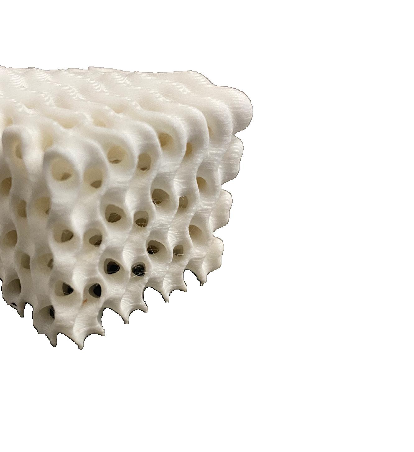
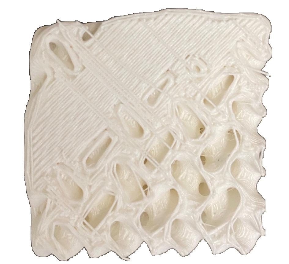
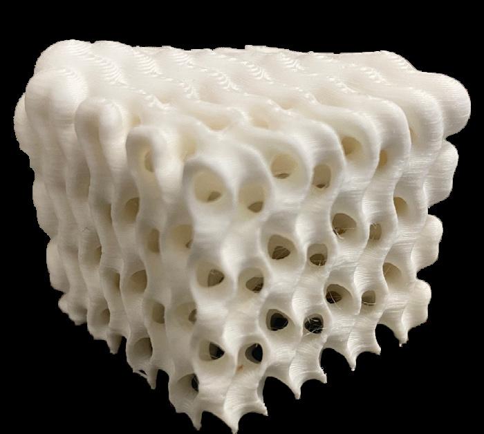
This design was created using a Grasshopper definition. It used the plugins, “Crystallon,” “Pufferfish,” and “Dendro.” Grasshopper was used to create a series of voxels that varied in size based off of a gradient between two points. This resulted in the corners of the geometry being puffier and thicker than the other corners. It was a complex geometry that took four hours to print.

The main problem that was present in the printing of this volume was stringing. This predominately occured in the corners where the nozzle had to stop extruding to bridge gaps in the geometry. This could have been fixed by slowing down the print speed of the print. There were also difficulties removing the raft because of the minimal touch points.





















































MODULE 2 WEEKS 4-9
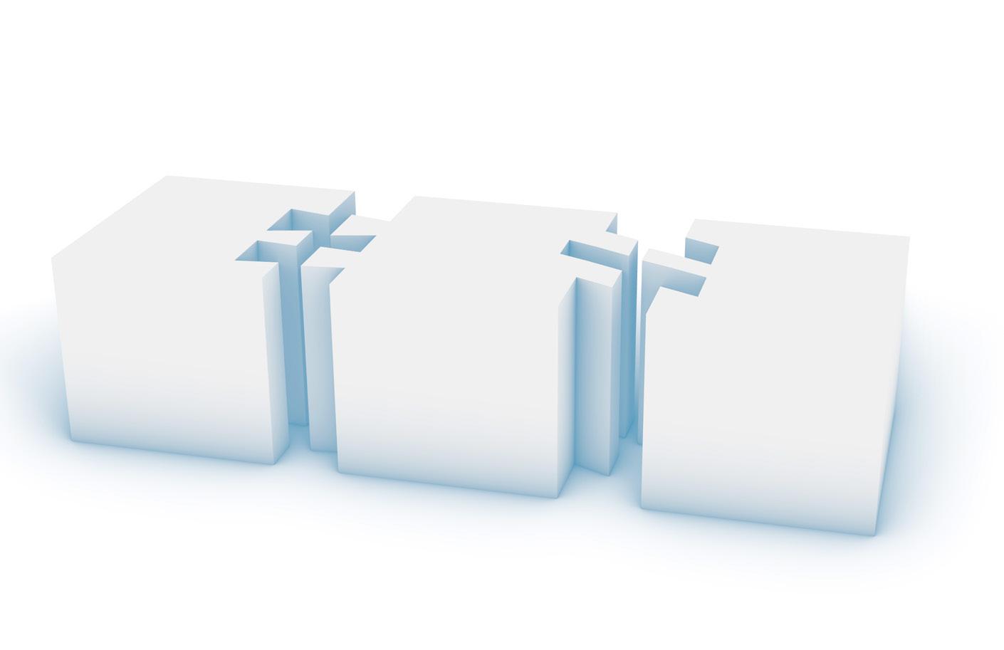
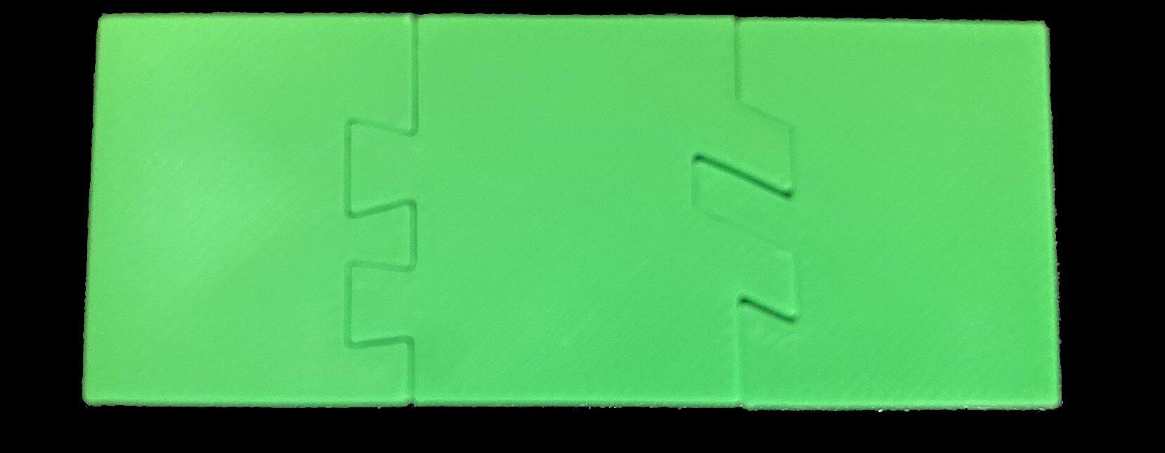
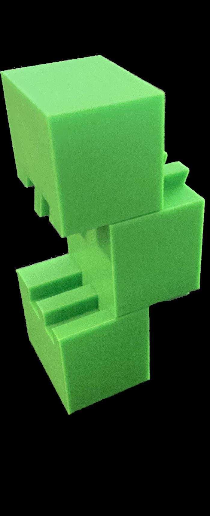
For this project, we explored simple connections between 3D printed volumes. The geometry was created by subdividing a rectangle into three sections. The dividing lines were then rebuilt to create saw tooth and angled connections. The tolerance for Prusa printers is around 0.3mm, so lines were offset by 0.15mm each.

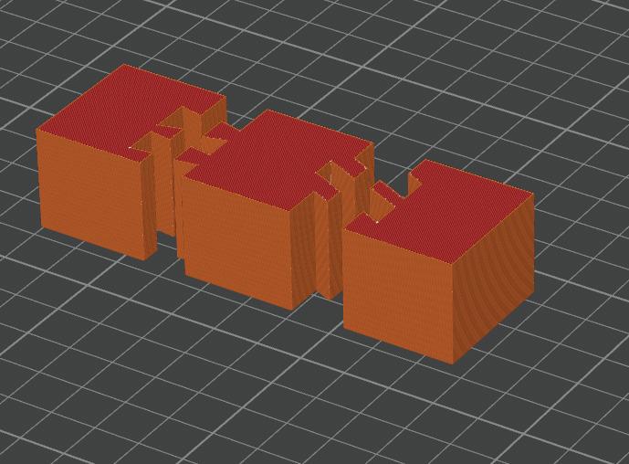

The volumes were printed on a Bambu P1S rather than the intended Prusa printer. Because of this the sides were brought in too far and the connection was looser than it should’ve been. The print came out well with no real problems and did not require a raft to adhere to the bed. The print took an hour and 8 minutes with a rectilinear infill.
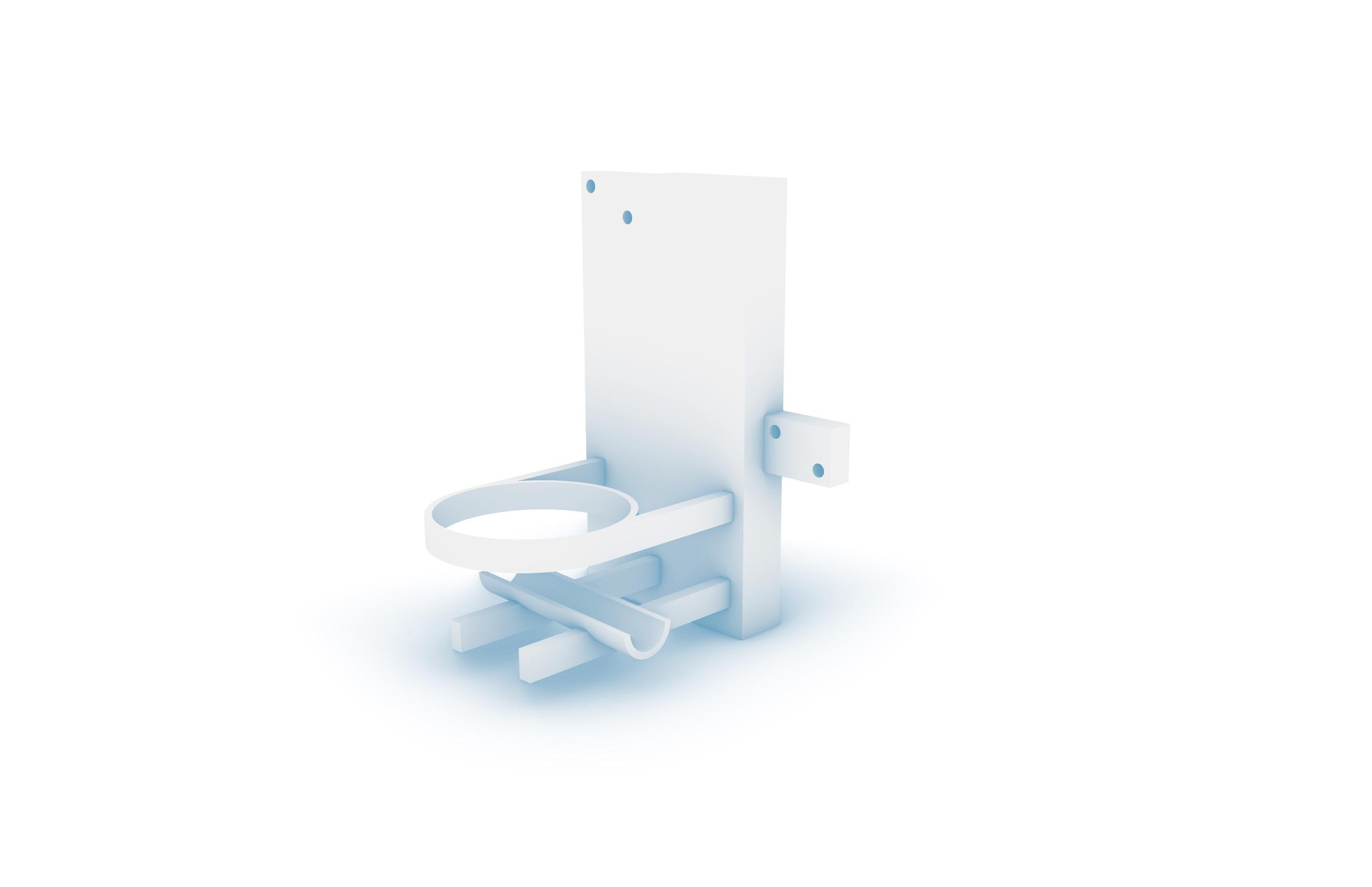
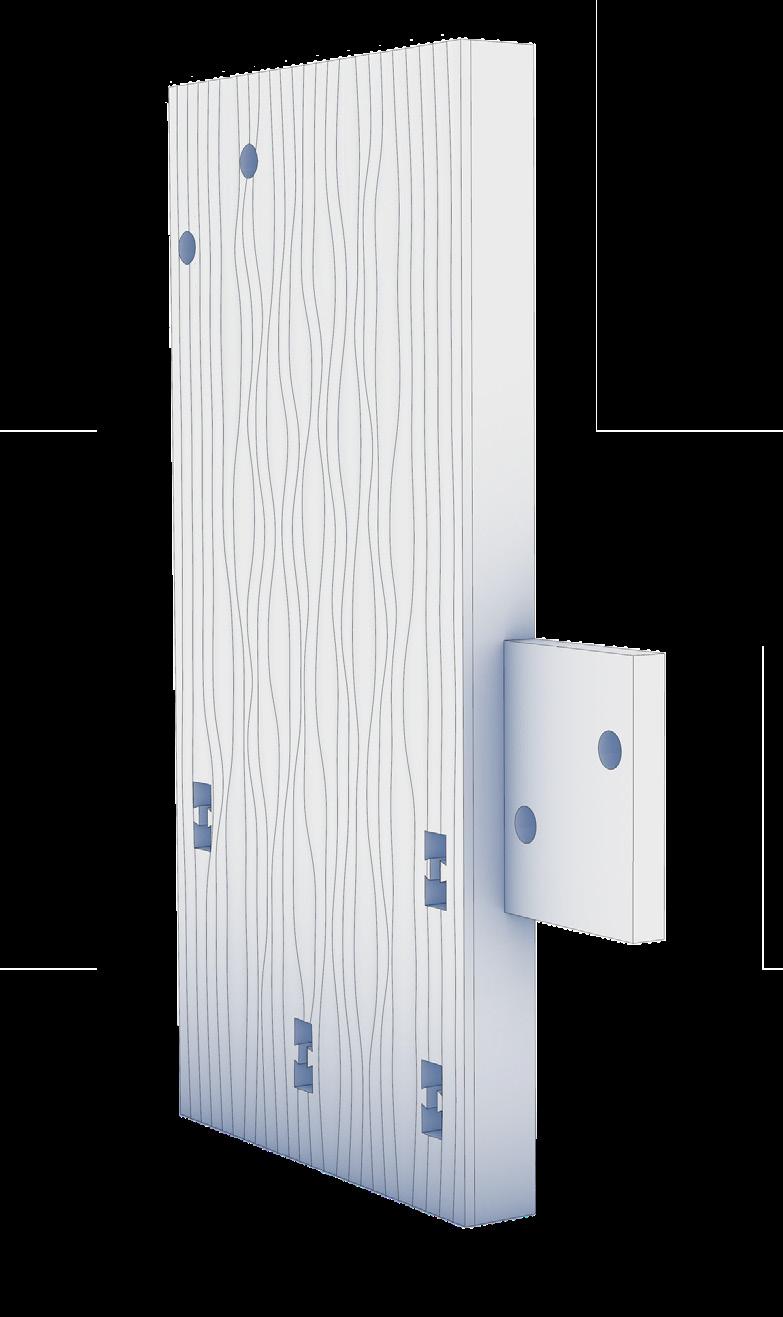
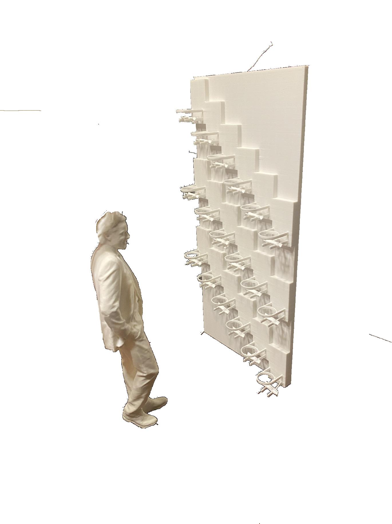
The design is for a wall mounted planter that can be repeated and attached to scale the of the planters. The planter is designed to have three parts. The base piece can be attached to a wall or backing board and has saw tooth openings to attach the other pieces. It is 4 inches wide by 8 inches tall with a depth of 1 inch. The arm is designed to hold 4 inch diameter pots. It aligns the
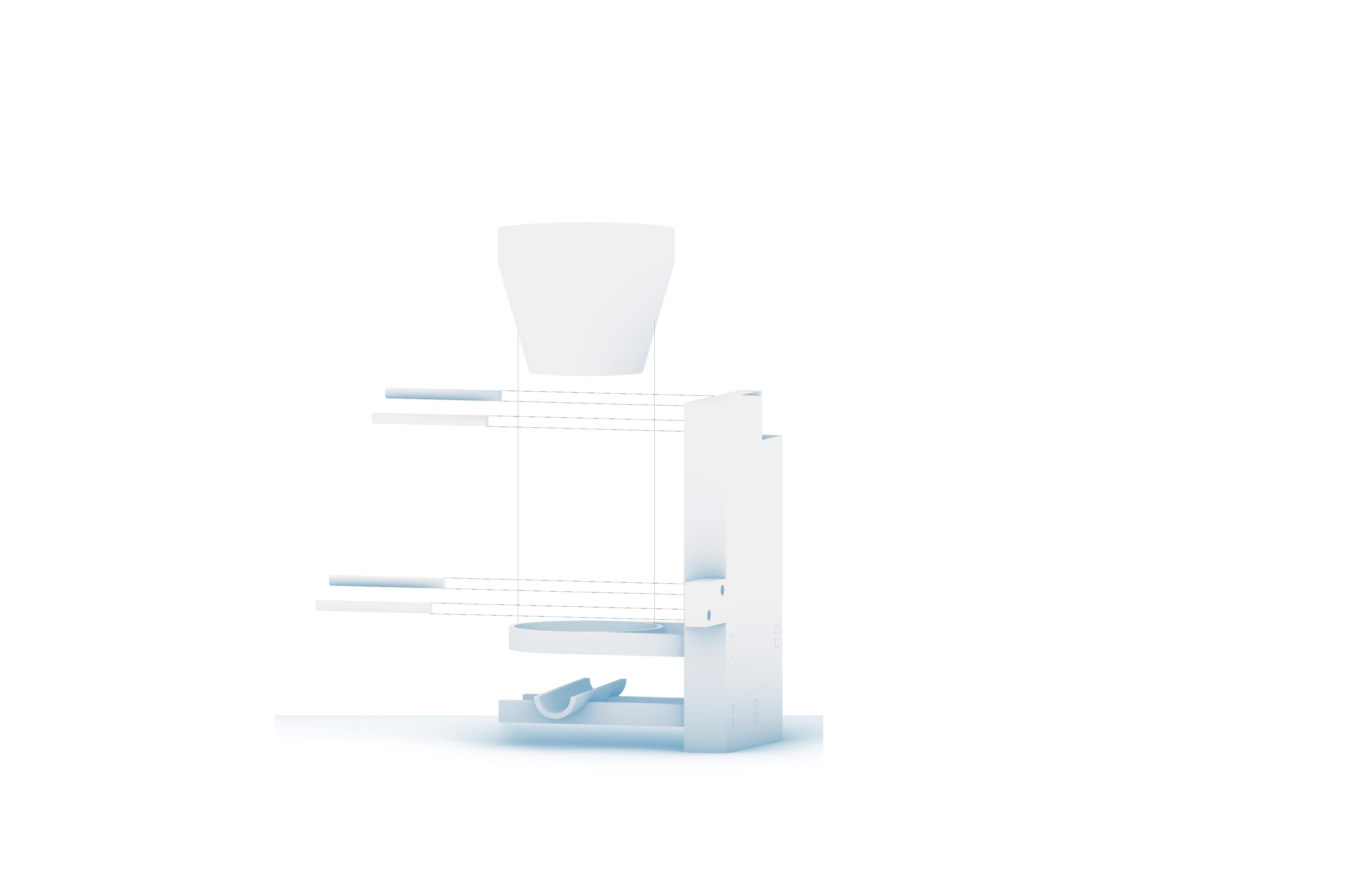
There will be a final base to print for the end of a sequence. It will act as the water collector for any excess water that makes it to the end of the line. The first iteration of the design tested the strength of pin connections. The iteration was done with no offset between female and male connections. This led to the pins being too difficult to attach without using a hammer.

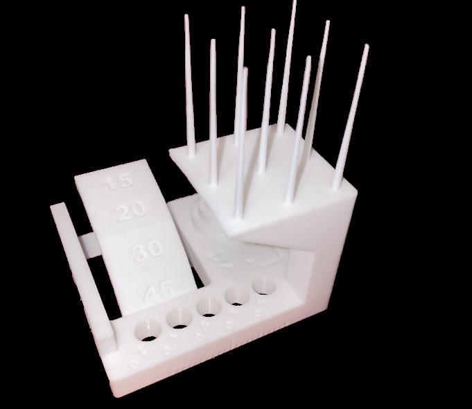
There were issues with the first test iteration of the design. There were channels inside of the volume in an attempt to transport water through the sequence. These were to small to funnel water properly, and were difficult to align through modules. Also, the tolerances of the dowels were not correctly set, so I printed a calibration test from MakerWorld to determine an offset of 0.1mm
There were a lot of lessons learned from this first iteration. First, it proved that dowels were a useful method for connecting the modules as long as they were at a 0.15mm offset. Also, when inserting the modules together through the middle, there was an empty space when printing that resulted in a rough surface due to supports.






















































CONNECTIONS CONTINUED


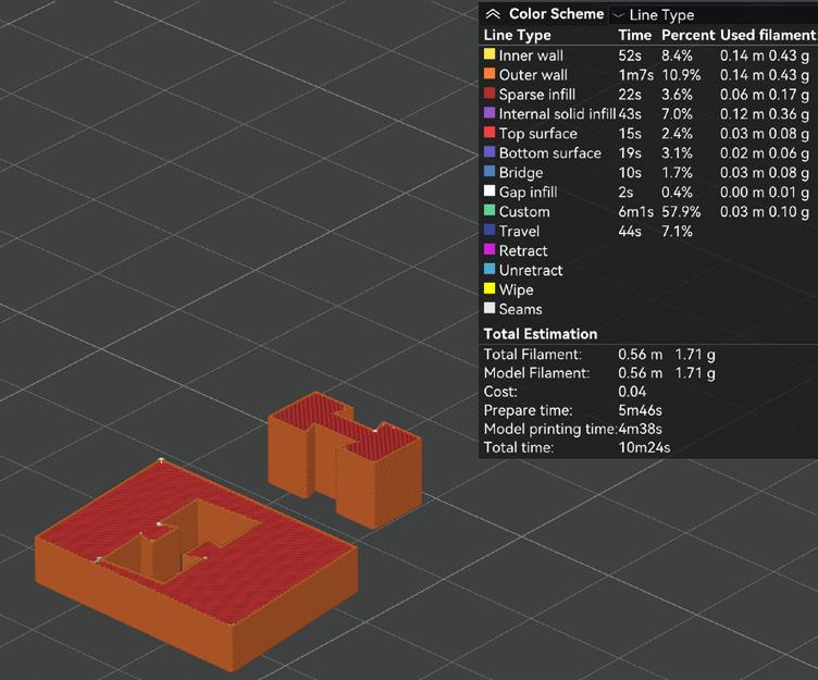
This iteration was meant to test joint connections between the three main parts of the design. There are four identical sliders that were boolean joined to the plant holder and the water funnel at their ends. Next the cut outs in the base were made by copying the same linework used to create the sliders. The linework was offset by 0.15mm to allow for a snug connection. It was



important to test this connection at a small scale before printing the entire piece, especially because the design was not fully finished at this point. To test the connection, the entire geometetry was brought into Bambu studio and sliced using the cut command to isolate just the male and female connectors. This reduced printing time from 4 hours to 10 minutes.
ADDING TEXTURE

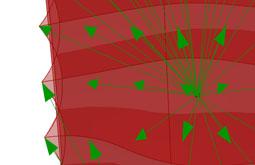

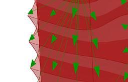

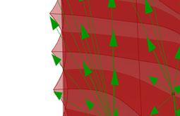


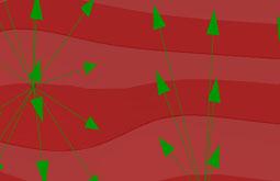
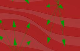
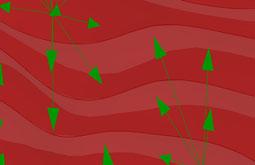


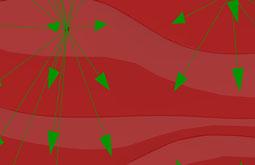


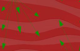
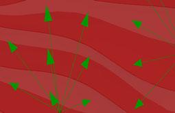
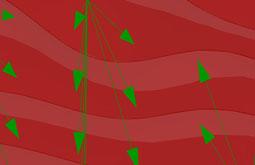

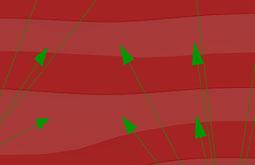

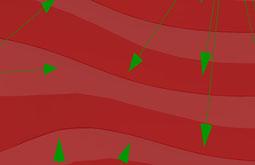

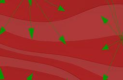


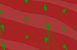

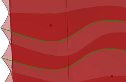


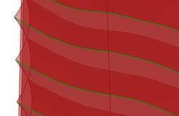

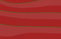
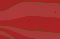

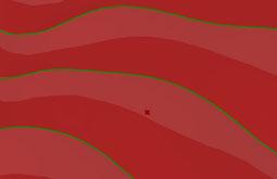
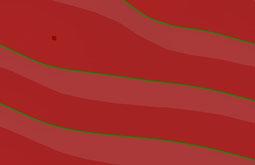

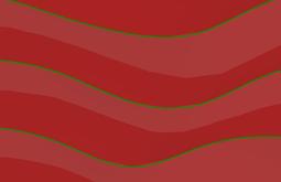


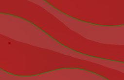

The textured surface of the design was created using a guide by “How to Rhino” on creating a wavey wall. This textured wall was then scaled to the proper size of the planter base. The offsets of the curves had to be adjusted to be scaled. Finally the previously designed cut outs were added as well as the connecting inset and offsets to attach multiple base modules.


The final design of the planter incorporated all of the previous tests. It had slider connections with 0.15mm offsets and dowel connections with 0.1mm offsets for the base connectors. The thickness of the base was decreased to lower wasted material. The wavey pattern was applied to the base to create a textured surface.
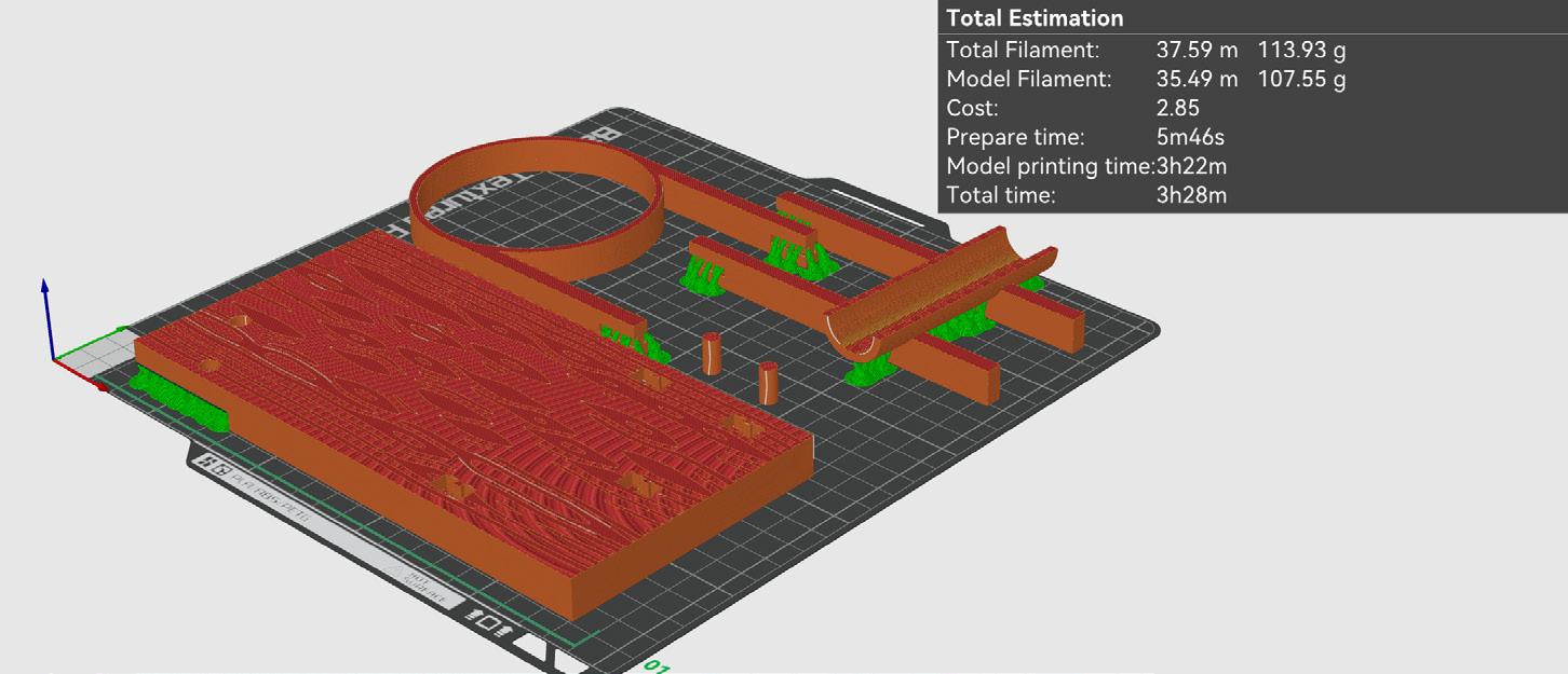
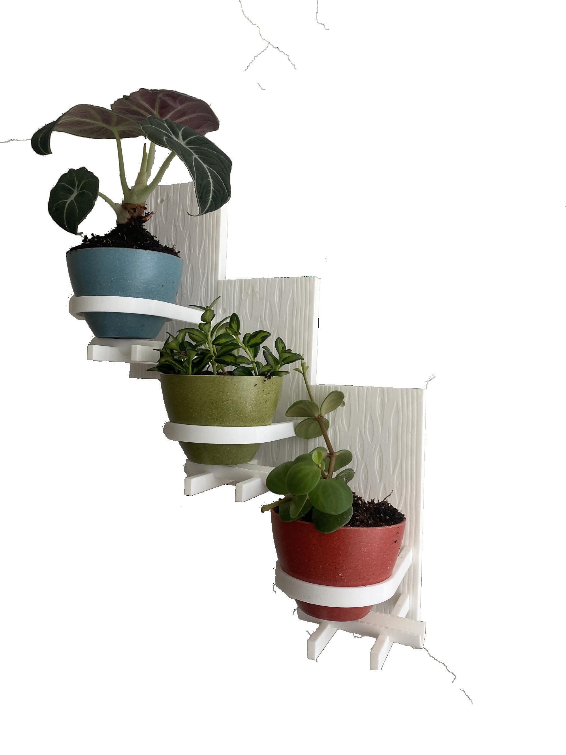
The final print of the planter came out very cleanly with only a small amount of post processing nessasary. The connectors in the top left of the base needed to be sanded down for a smoother connection. They came out rough because they were overhanging during the print and were supported by auto generated tree supports. There were also some dark spots on the Fig 34.

textured suface of the base. These seemed to appear in areas where the texture was inset right on top of an infill for the base. This could be fixed in future iterations by having a denser infill or having multiple solid layers between the base and the textured surface. Besides those problems, the end product was good quality and stayed identical through multiple prints.