
1
MODULE 1 2 MODULE 2
VASE: Pg 6-9
INFILL WALL: Pg 10-13
INFILL PATTERN: Pg 14-17
GRADIENT INFILL: Pg 18-21
TOLERANCE TEST: Pg 24-31
MODULAR ASSEMBLIES: Pg 32-37


VASE: Pg 6-9
INFILL WALL: Pg 10-13
INFILL PATTERN: Pg 14-17
GRADIENT INFILL: Pg 18-21
TOLERANCE TEST: Pg 24-31
MODULAR ASSEMBLIES: Pg 32-37

INTRO TO 3D PRINTING

VASE PRINT
VASE DESIGN, METHODS & PROCESSES
The design concept of this vase stems from an array of 5 or more circles spaced across a vertical line (see Fig. 1 ). The diameters of each circle were then manipulated and then lofted to create an organic form as seen in Fig. 2. following this, the process to 3D print this was simple. Export the file as an STL out of Rhino and bring that into the software Prusa or Bambu, to be sliced.

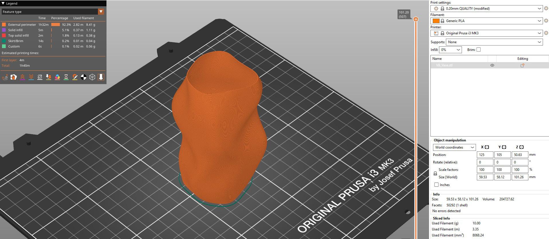
In the slicer itself, we adjutsed the print settings to have it print via “Spiral Vase” only. This ensures that the tool path of the printer only runs around the perimeter of the object, thus printing with no infill (Fig. 3).
The slicer then runs a G-code slicing simulation that may show any failures in printing and follows up with warnings and suggestions to improve. The G-code is then

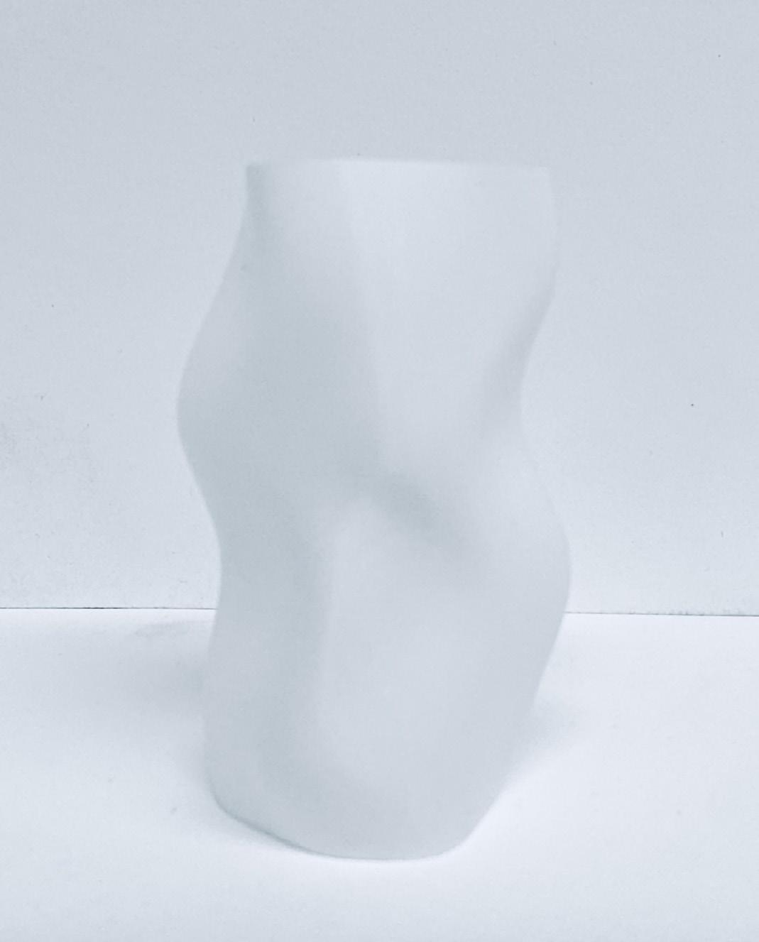
exported and plugged into the machine. In this case, the vase was printed with the Bambu X1 Carbon printer was completed in around 30 minutes as compared to an hour or more for the Prusa Slicer runtime.
1_ Rhino, line work (curves)
2_ 3D model creation in
3_ Prusa tool path in Rhino
4_Model in Prusa Slicer (preview)


5_ Photography, physical model
6_ Photography, physical model
7_ Photography, physical model
8_ Prusa tool path simulation preview

5_ Photography, physical model
6_ Photography, physical model
7_ Photography, physical model
8_ Prusa tool path simulation preview

WALL PRINT
INFILL PRINTING DESIGN & PROCESSES
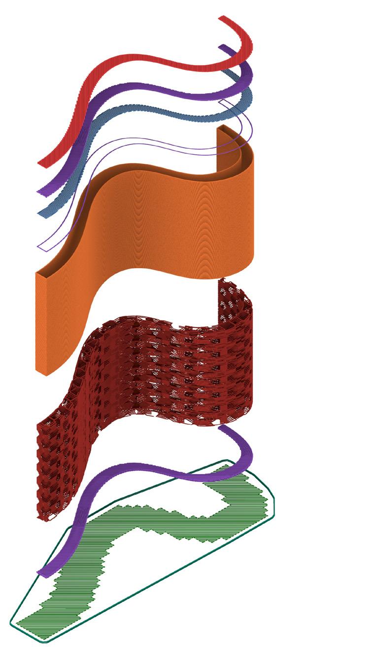
The design idea of this wall began as a series of points along a curve (polyline) in Rhino, which were then extruded to create a wall with some thickness (fig. 9). The wall was then exported as an STL, similar to the Vase, and then imported into the Prusa Slicer software. In Prusa, the model was scaled and further manipulated, with higher degree of wall curvature added along with

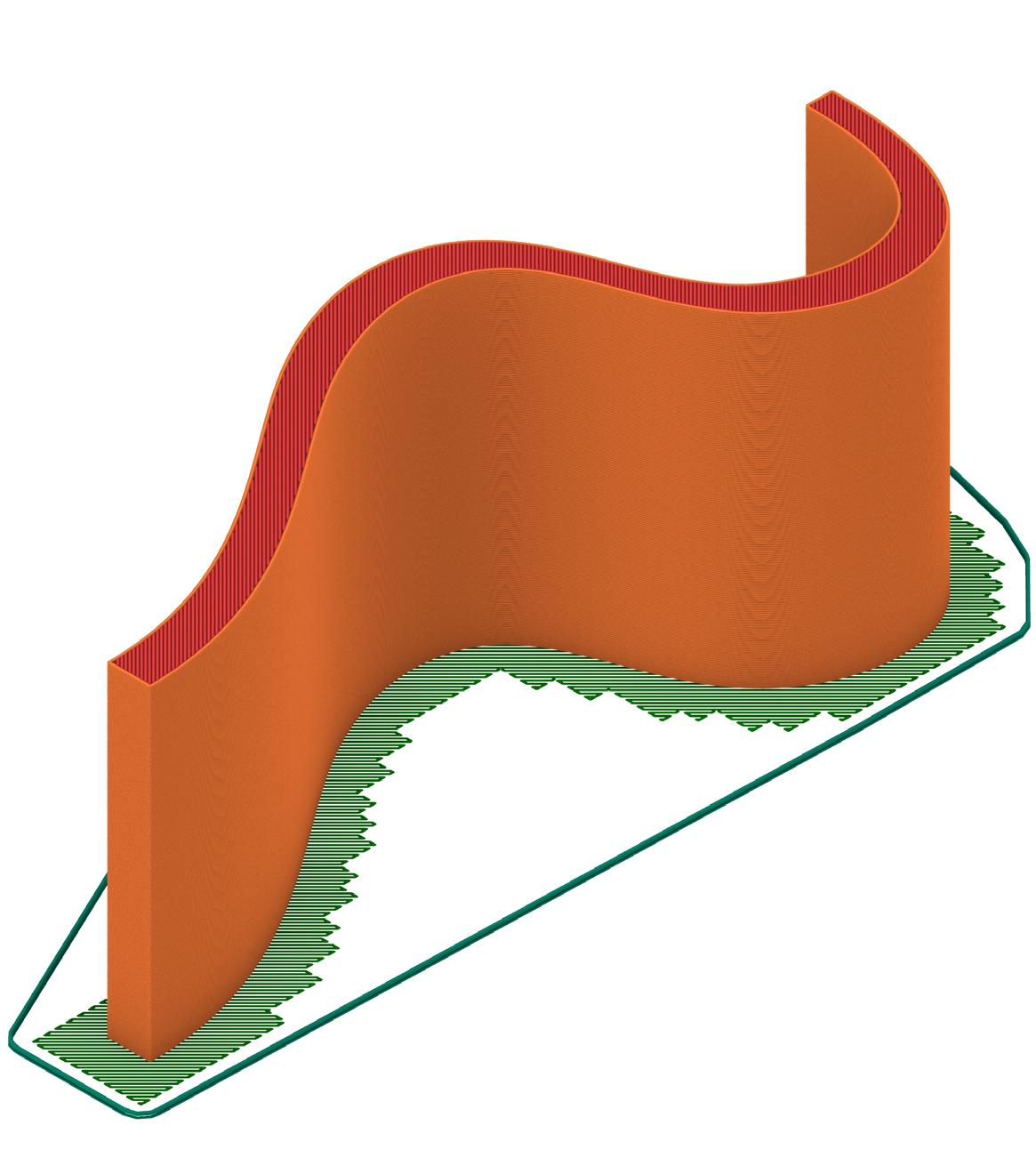
a layer of varying thickness throughout the wall. For this print, the wall had an infill of roughly 15%, which is standard. The pattern used was a 3D honeycomb infill pattern which is highlighted in the next segment.
9_
10_
11_
12_
13_ Photography, physical model


10_


14_ Photography, physical model
15_ Photography, physical model
16_ Prusa tool path simulation preview
17_ Rhino, exploded axonometric highlighting print layers

14_ Photography, physical model
15_ Photography, physical model
16_ Prusa tool path simulation preview
17_ Rhino, exploded axonometric highlighting print layers

INFILL WITHOUT WALLS
INFILL PATTERN PRINT METHODS & PROCESSES
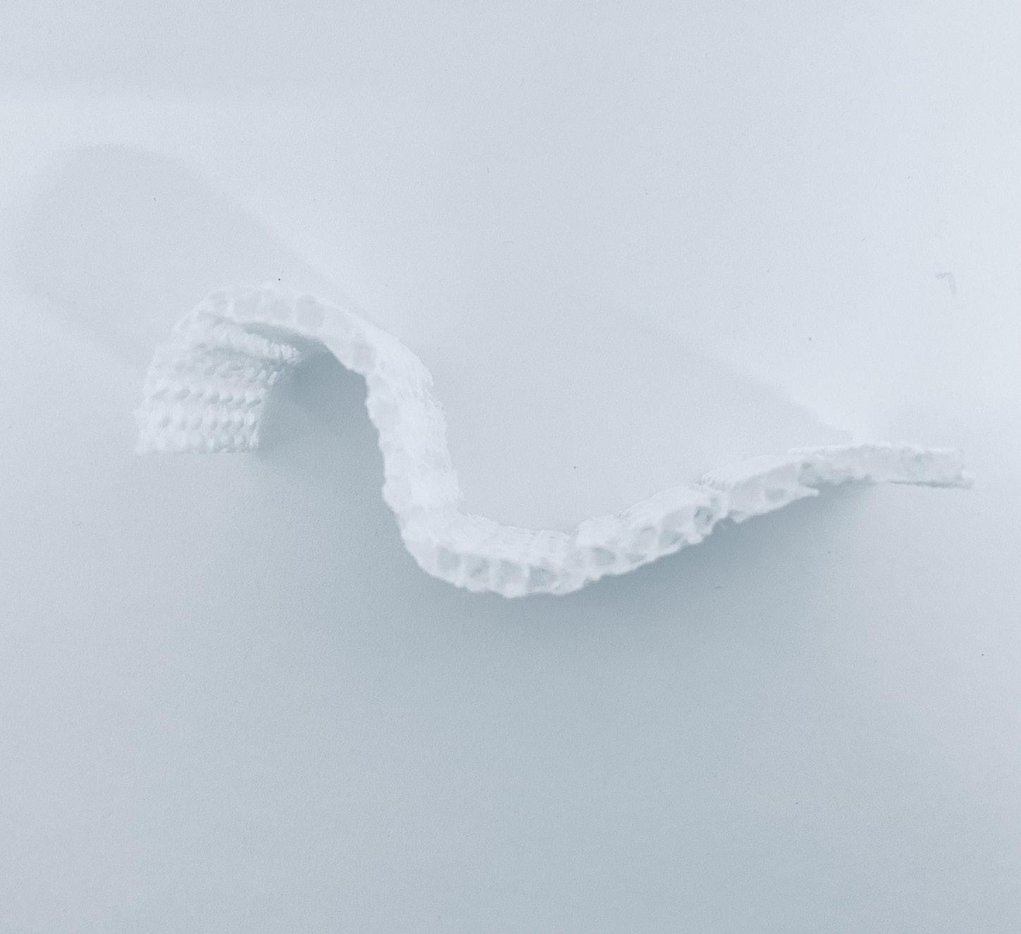
Printing an infill-only structure with a 3D honeycomb pattern involves a series of adjustments from design through slicing. Starting in Rhino, the model is kept minimal, focusing on generating a robust 3D honeycomb In Prusa a 3D honeycomb pattern was selected followed by an adjustment to the infill percentage to optimize the pattern’s stability and aesthetic appeal.
Once the structure is complete, it’s exported as an STL file. In PrusaSlicer, specific settings ensure that only the infill prints, without external perimeters. Setting the perimeter count to zero and disabling both top and bottom layers creates an infill-only model. the 3D Honeycomb pattern as the infill style further enhances the structural complexity, adding depth
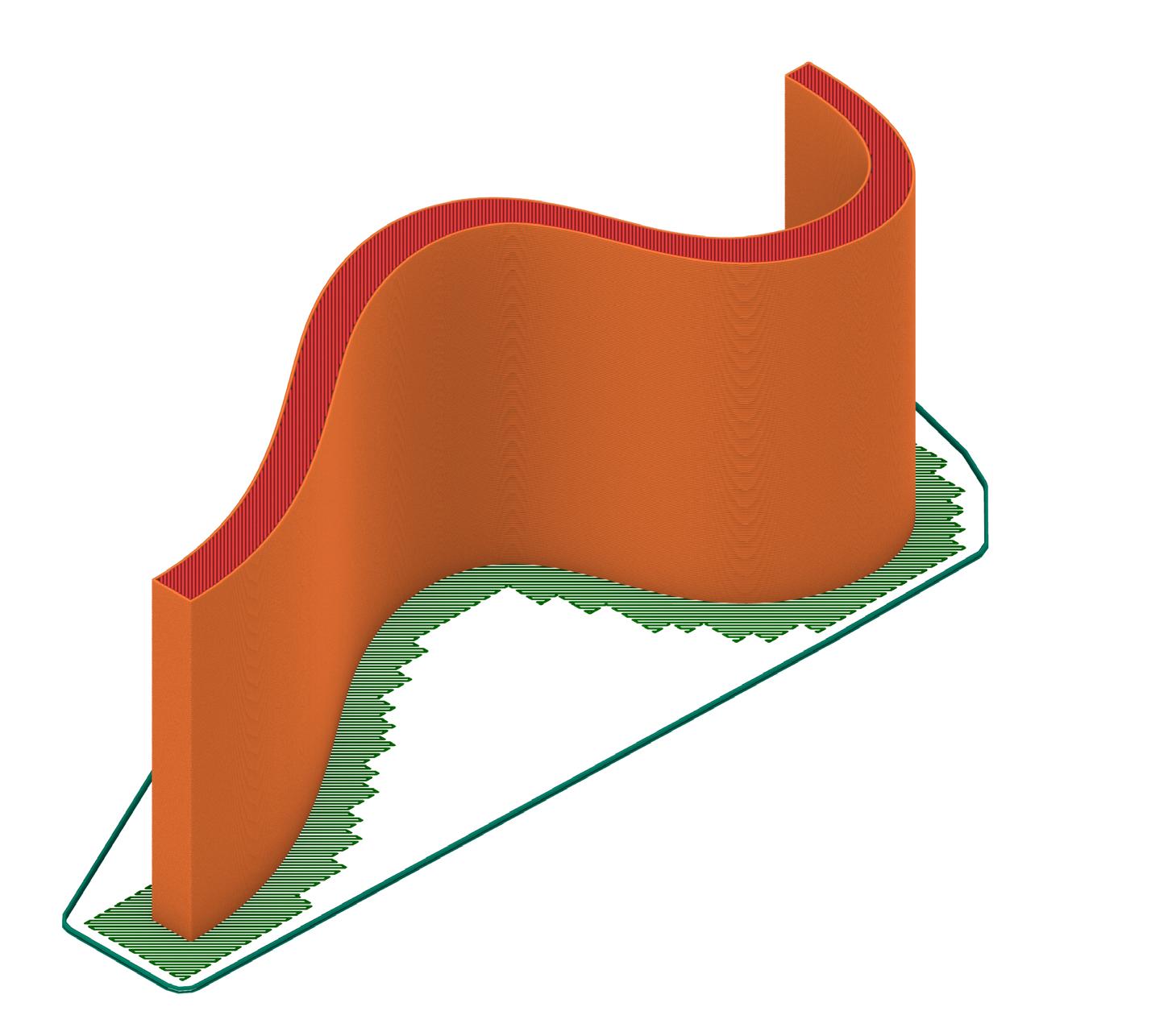
and dimension. The infill density was chosen at 10% to balance between strength and filament usage, ensuring a visually striking honeycomb pattern without the need for outer walls. The sliced file generates G-code that, when sent to the printer, results in a freestanding 3D honeycomb structure, layer by layer, showcasing the intricate infill pattern.
18_ Rhino, infill toolpath
19_ Rhino, infill wall toolpath form
20_ Photography, physical model
21_ Photography, physical model


22_ Photography, physical model
23_ Photography, physical model
24_ Photography, physical model
25_ Prusa, toolpath simulation


22_ Photography, physical model
23_ Photography, physical model
24_ Photography, physical model
25_ Prusa, toolpath simulation


GRADIENT INFILL PATTERNS
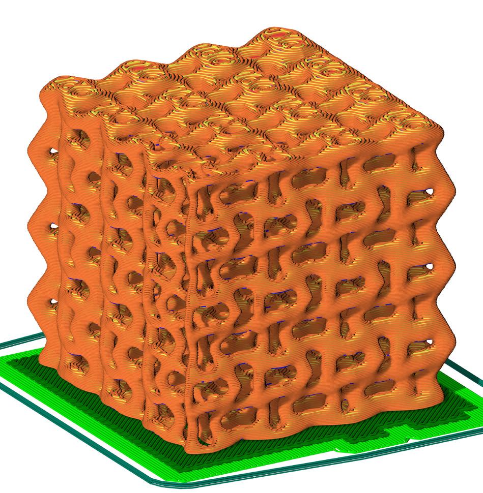
GRADIENT INFILL DESIGN, METHODS & PROCESSES
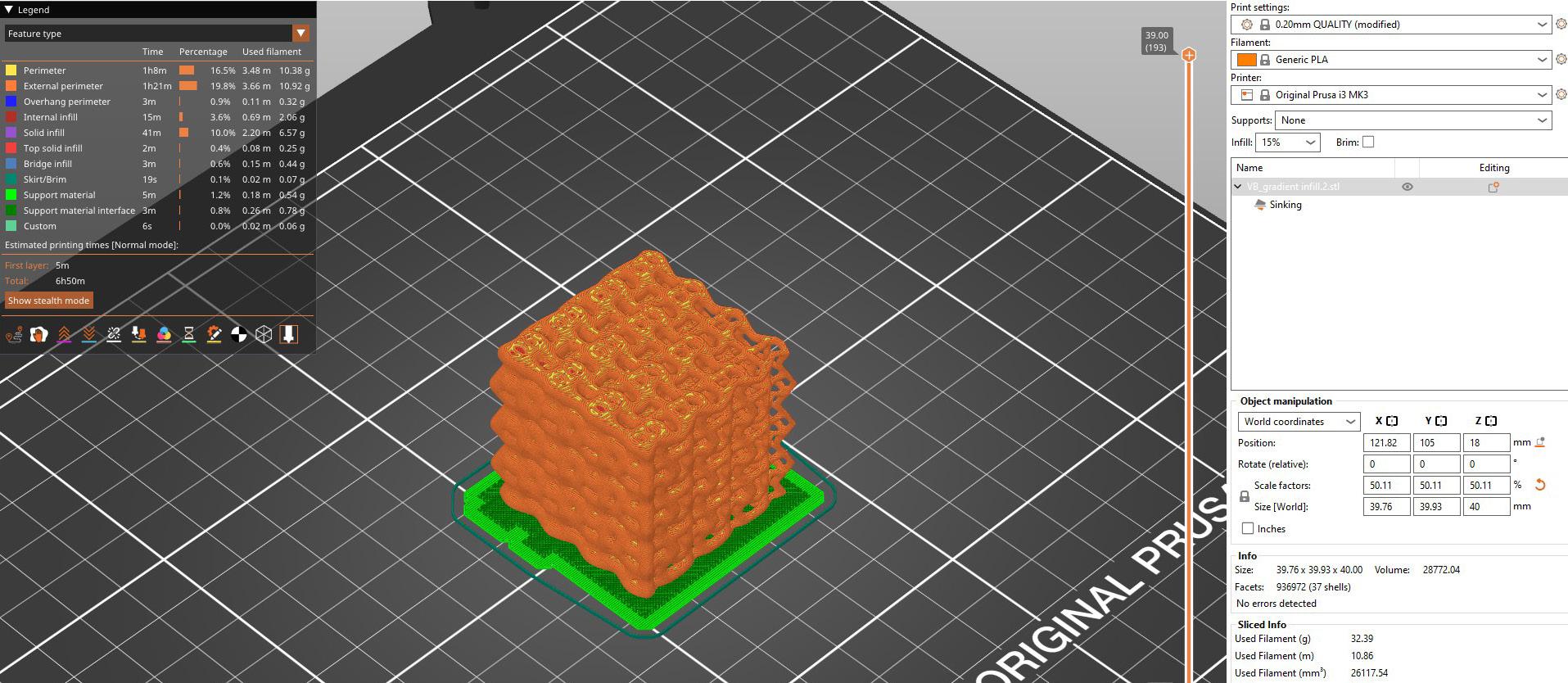
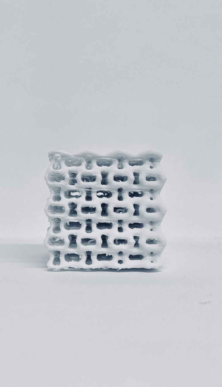
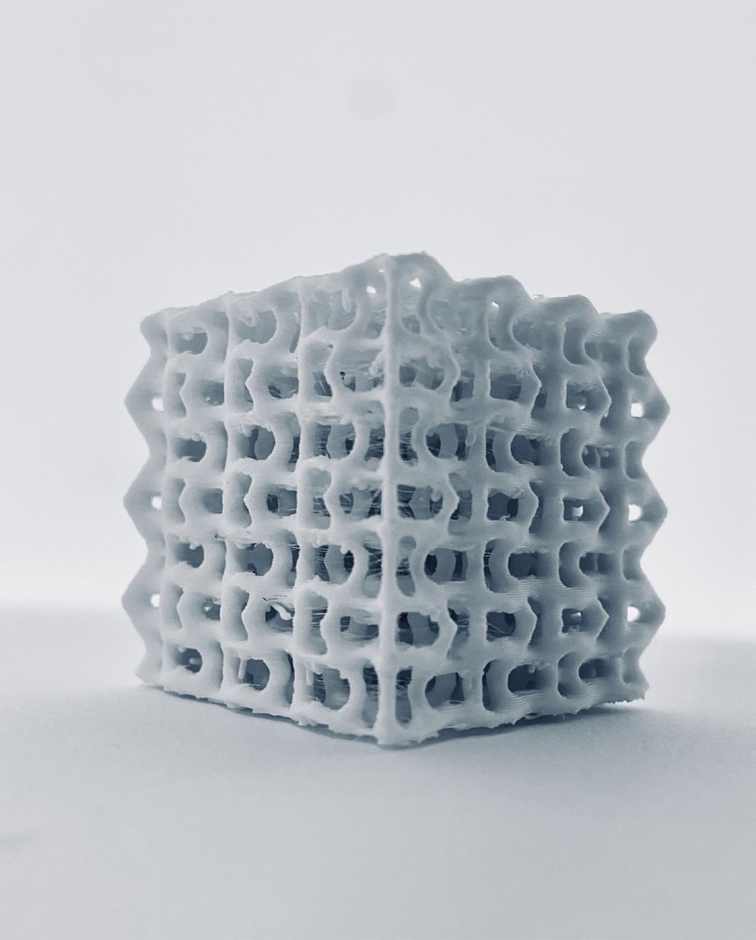
Creating a 3D-printed gradient infill involves several steps, starting with Rhino and Grasshopper for design and ending with PrusaSlicer for printing. In Rhino, the model is designed, then Grasshopper is used to create a gradient infill pattern, often with the help of plugins like Pufferfish or Weaverbird to generate complex geometric variations within the infill.
This gradient can be controlled by parameters like density, scale, or orientation, creating a smooth transition from dense to sparse fill. Once the pattern is finalized, it’s baked into Rhino to create a mesh, which can be exported as an STL file. In PrusaSlicer, the STL is imported, and settings are adjusted to match the model’s specific requirements, including any
additional layer or infill adjustments that the slicer offers. The file is then sliced, generating G-code ready for printing. Finally, the G-code is transferred to the 3D printer, which produces a physical model with the custom gradient infill pattern as designed.
27_
28_
29_Model

30_ Photography, physical model
31_ Photography, physical model
32_ Photography, physical model
33_ Prusa tool path simulation preview
30_ Photography, physical model 31_ Photography, physical model


TOLERANCE TESTING
MODULAR TOLERANCE TEST METHODS & PROCESSES
This design was created using Rhino and Grasshopper to develop interlocking modular assemblies featuring hexagonal faces with nonplanar, topological contact surfaces.
The hexagonal geometry was selected for its structural stability and tessellation advantages, allowing seamless connections and efficient load distribution.

The overall form was intentionally designed to lean at an angle of 20 degrees, introducing a dynamic visual element while maintaining the structural capacity to hold and support the interlocking pieces securely.
The non-planar surfaces enhance friction and ensure the modules lock
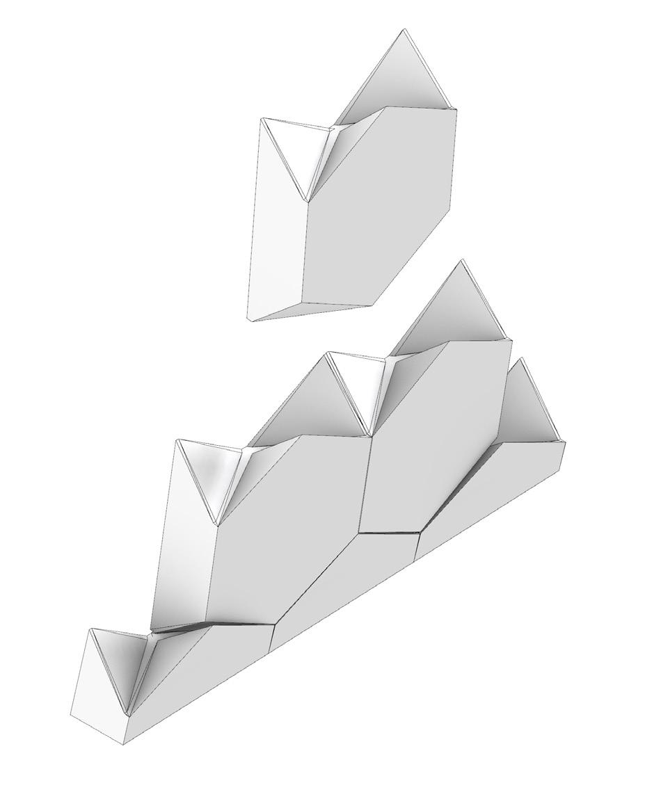
firmly. Tolerances of 0.3mm were rigorously tested during prototyping to balance precision with ease of assembly. Designed parametrically, the geometry was iteratively refined for optimal fit and functionality before being prepared for 3D printing.
34_
35_
36_
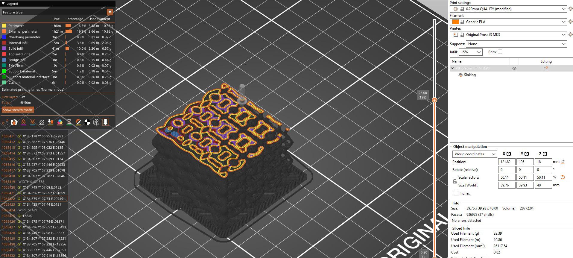
37_Model in Prusa Slicer (preview)
38_ 3D printed model in Prusa Bed
39_ 3D printed model in Prusa Bed


40_ Photography, physical model
41_ Photography, physical model
42_ Photography, physical model
43_ Prusa tool path simulation preview
44_ Photography, physical model


40_ Photography, physical model
41_ Photography, physical model
42_ Photography, physical model
43_ Prusa tool path simulation preview
44_ Photography, physical model

MODULAR INTERLOCKING SYSTEM
CONNECTION DESIGN, TESTING & PROCESSES
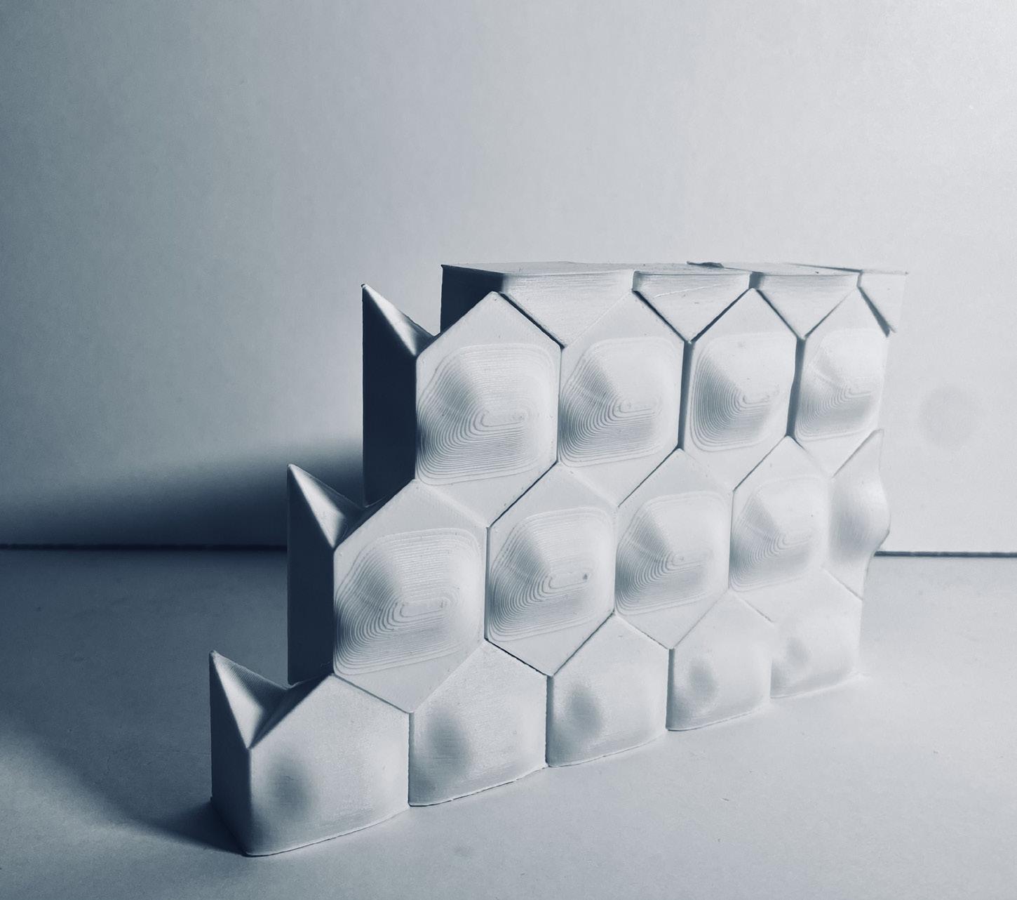
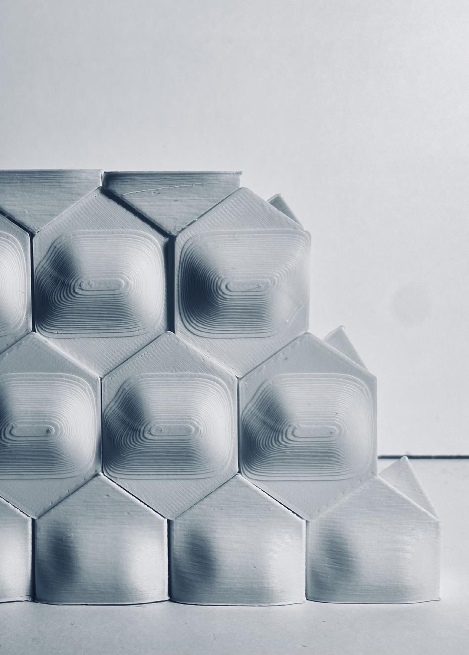
The modular assembly design evolved to enhance its structural capacity by increasing the depth of the modules, allowing them to support greater loads. This was achieved by creating more surface area contact between the interlocking pieces, improving their overall stability and durability. connection but also added a sense of dimension and complexity to
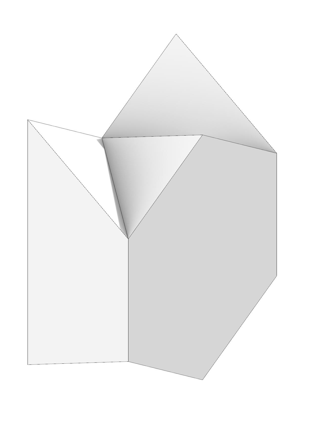

the structure. The increased depth not only strengthened the physical connection but also added a sense of dimension and complexity to the structure. Additionally, the flat hexagonal face was transformed into a subtly curved surface, introducing a dynamic, wavy effect that propagates throughout the assembly when the modules are connected.
This curvature adds visual interest and breaks the monotony of flat geometries, creating a more organic and fluid aesthetic. The wavy pattern also contributes to the structure’s ability to distribute loads evenly across its surface, enhancing its performance as an angled assembly while maintaining its interlocking functionality.
45_ 3D model creation in
46_ 3D model creation in
47_ 3D model creation in
48_Model in Prusa Slicer (preview)
49_Photography, physical model



50_Photography, physical model
51_Photography, physical model
52_Photography, physical model
53_Photography, physical model
54_Photography, physical model


50_Photography, physical model
51_Photography, physical model
52_Photography, physical model
53_Photography, physical model
54_Photography, physical model
MODULAR INTERLOCKING SYSTEM
MODULAR ARRANGMENT - 1/4” SCALE
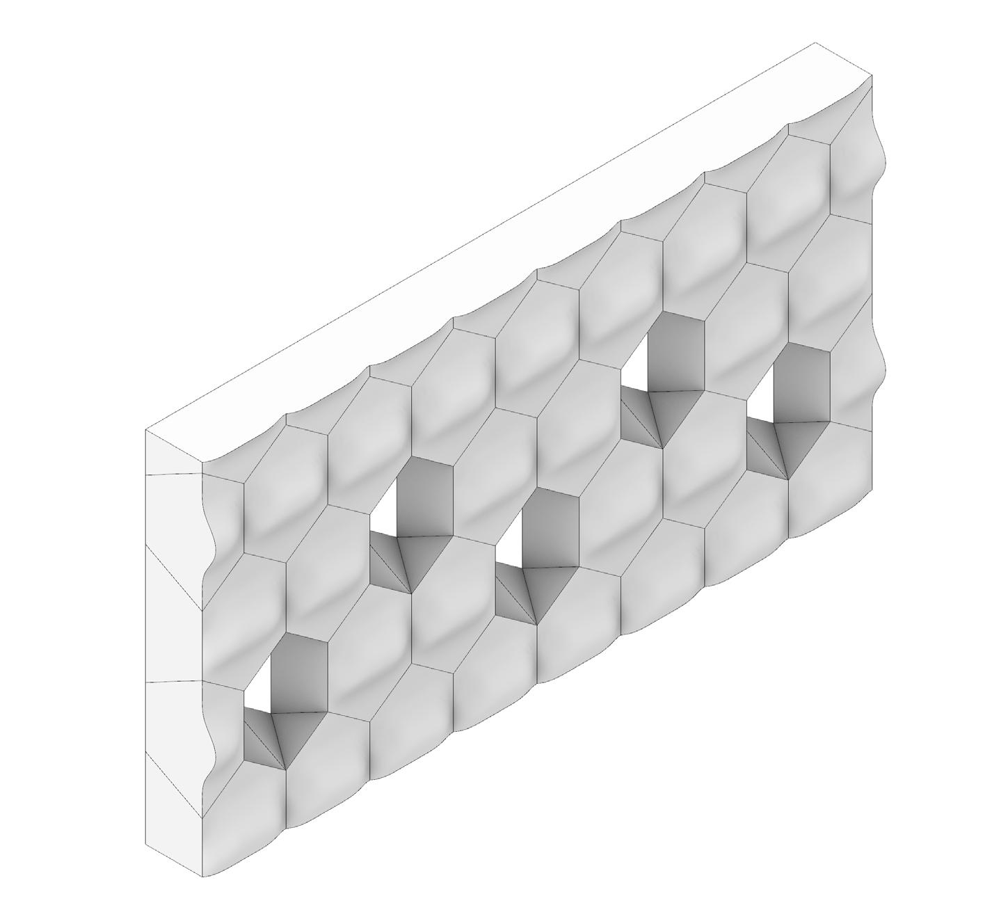
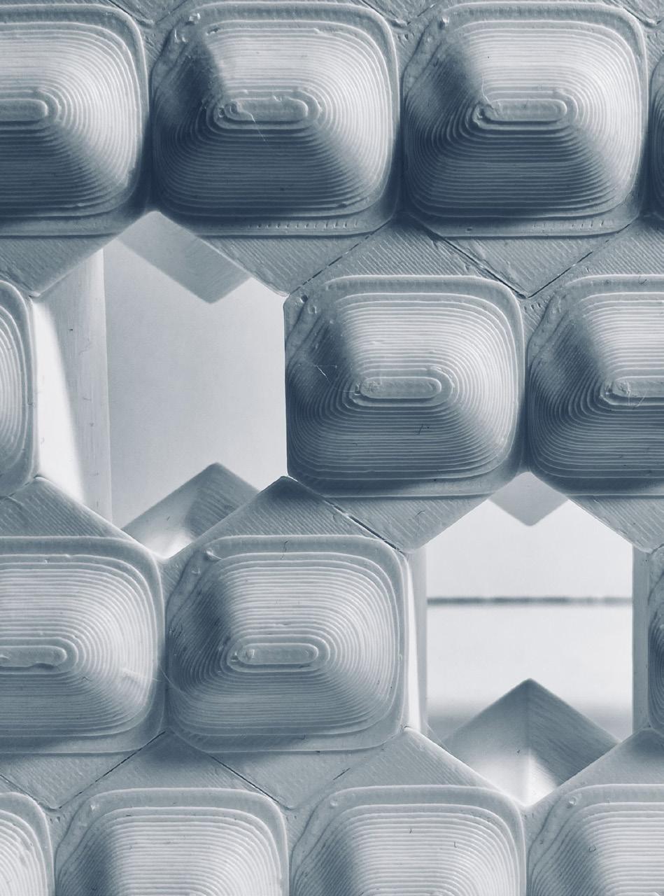
This aggregation of the modules at an architectural scale is an example of the wall assembly of the modular design and its application. The modular design not only allows for ease of fabrication and assembly but also theoretically can be applied to other materials as well.
This is illustrated through the base and top modules, which are offcuts of each other, minimizing manufacturing costs and fabrication intensity in areas such as Timber or Metal.

This assembly can be used as an acoustical wall mock up or a display piece and possibly can be load bearing.
55_ 3D model creation in Rhino
56_ 3D model creation in Rhino
57_Model in Prusa Slicer (preview)
58_Photography, physical model

55_ 3D model creation in
56_ 3D model creation in
57_Model in Prusa Slicer (preview)
58_Photography, physical model


59_Photography, physical model
60_ Prusa tool path in Rhino
61_Photography, physical model
62_Photography, physical model

59_Photography, physical model
60_ Prusa tool path in Rhino
61_Photography, physical model
62_Photography, physical model

MODULAR INTERLOCKING SYSTEM
TESTING LARGE ITERATIONS
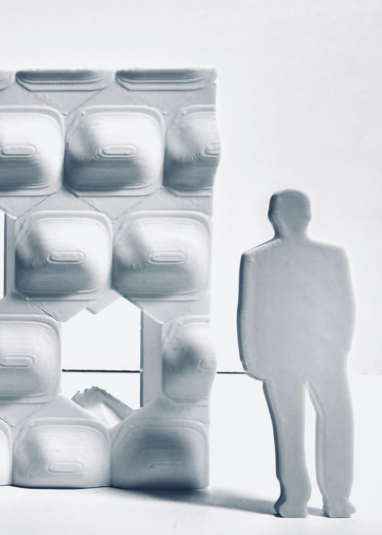
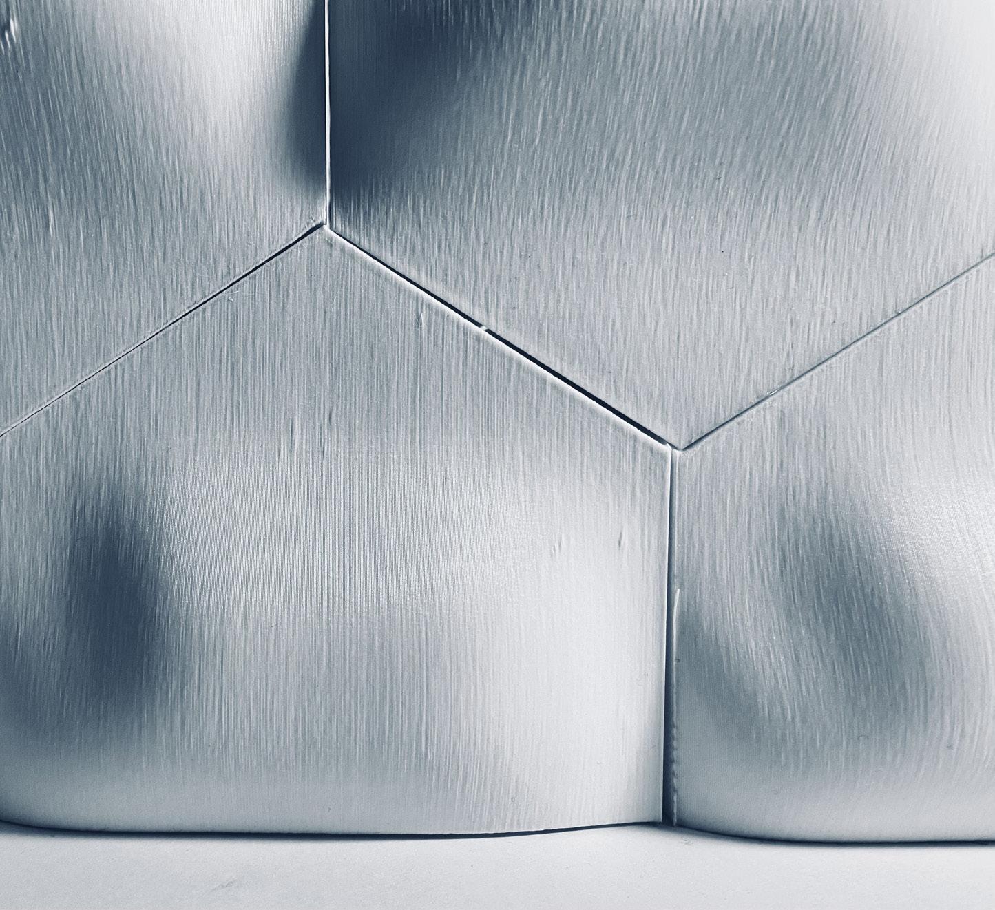
At a larger scale, these modules are designed to interlock seamlessly, enabling the creation of alternative modular arrangements that are more rectilinear in form. This flexibility allows for the adaptation of the design into practical configurations, such as vertically or horizontally aligned systems, making them versatile for different uses. Additionally, the offcuts from the
modules are purposefully designed to interlock as well, forming separate modules of entirely different forms. This efficient use of material not only minimizes waste but also introduces new design possibilities by creating complementary pieces. These secondary modules can be assembled into unique configurations, adding to the
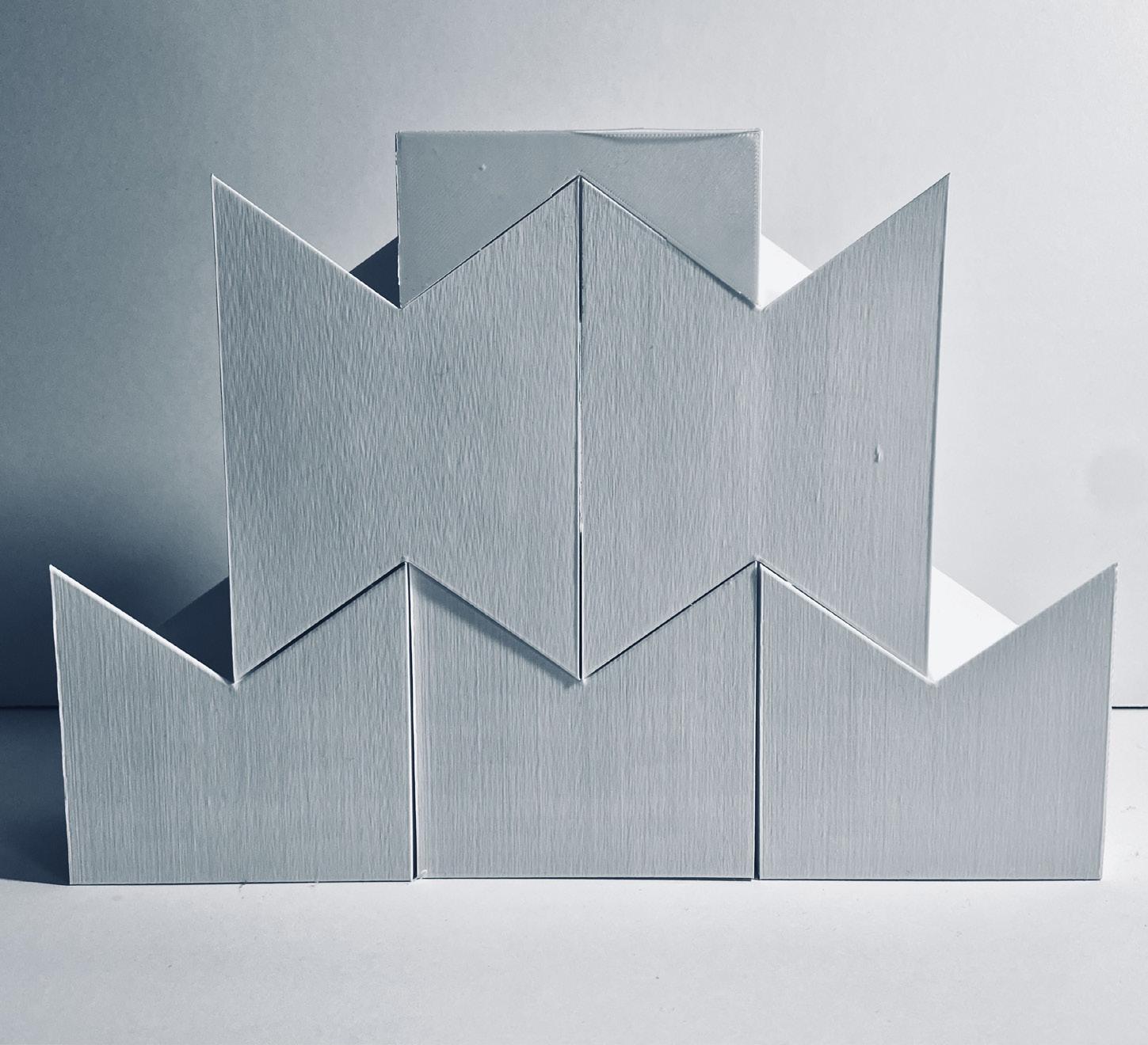
system’s adaptability. The rectilinear arrangements and their offcut-derived counterparts can serve functional purposes, such as modular storage units. The interlocking approach enables easy assembly, disassembly, and reconfiguration, catering to various spatial and organizational needs while maintaining a cohesive aesthetic.
63_ Photography, physical model
64_ Photography, physical model
65_ Photography, physical model
66_ Photography, physical model

63_ Photography, physical model
64_ Photography, physical model
65_ Photography, physical model
66_ Photography, physical model
