DESIGN & FABRICATION OF INDOOR INFRASTRUCTURE FOR LIVING SYSTEMS
WINTER 2023 ARCHITECTURE STUDIO


WINTER 2023 ARCHITECTURE STUDIO



Charlotte Kamman is an undergraduate student and Stamps Scholar at the University of Oregon. She is in her third year of the Bachelor of Architecture Program in the University of Oregon’s School of Architecture and Environment. Charlotte’s interests include sustainability, environmental stewardship, land management, building science, and urban design. She hopes to use her professional career to address climate change and systemic inequities in ways that balance human and environmental needs. Charlotte is also a member of the UO’s Clark Honors College and is pursuing additional studies in Spanish and classical music.

This project was completed as part of a University of Oregon Architectural Design (ARCH 484) studio course entitled “Pompidou 2” led by Professor Mary Polites during winter term, 2023. This project explores different scales at which living plant systems can be incorporated into the indoor built environment. This project strives to design systems to support plant life based on natural patterns of plant growth.
As suggested by the title “Pompidou 2,” mechanical systems play a large role in this project. Growing plants indoors is an intensive process that requires high inputs of water, fertilizer, and light, and electricity. Mechanical systems are therefore a necessity to support indoor plant life.
Taking inspiration from the Centre Pompidou in France, this project explores the aesthetic potential of mechanical systems. In contrast to common practice, the mechanical systems required to support indoor plant life in this project are prominently highlighted in the space.
This project explores novel ways to support indoor plant life at a variety of scales. Phase I explores the design of scaffolds to support plant life at the scale of individual cells and root structures. Phase II considers how a system supporting plant life can be beautifully integrated into an existing wall assembly. Phase III explores the potential to implement strategies developed in the second phase in a variety of contexts.
The global issues of climate change and poor public health create a need to redesign the built environment to be more sustainable. The integration of plant life into the indoor environment has the potential to bring positive impacts for both human and environmental health.
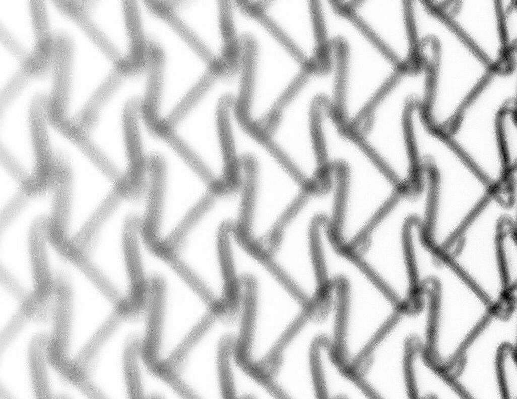
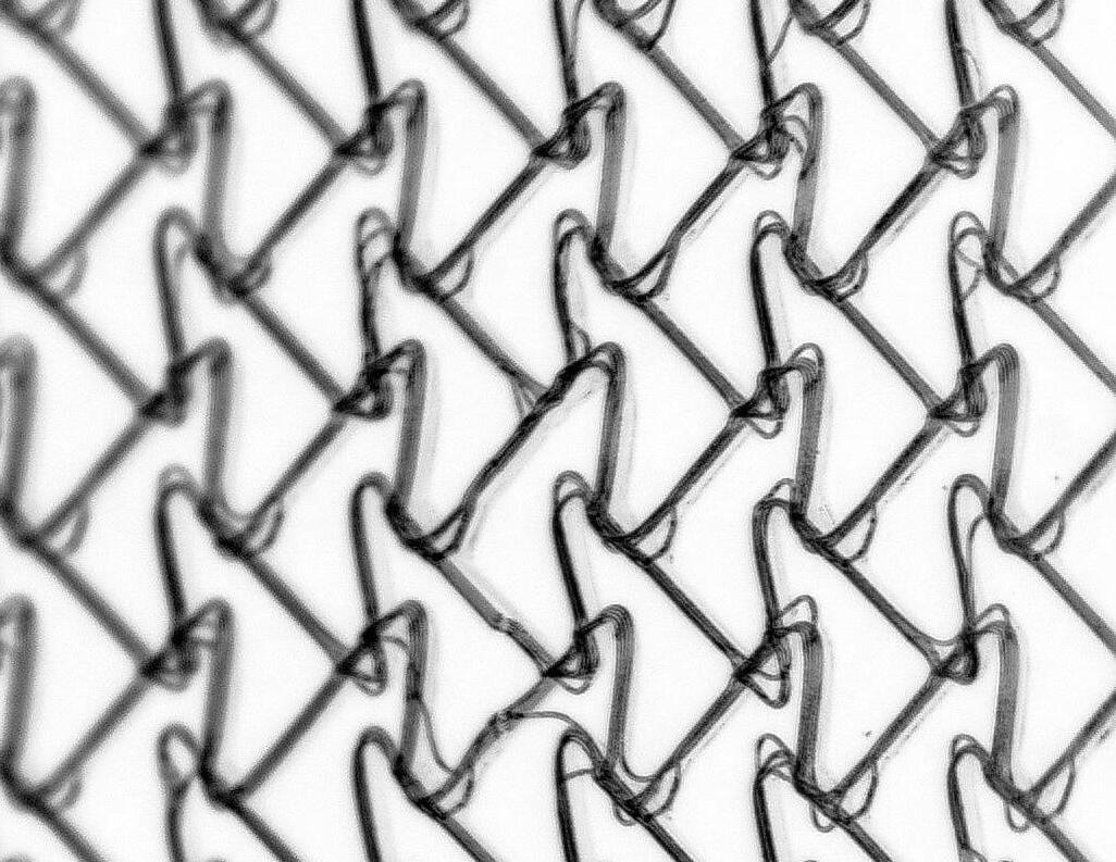
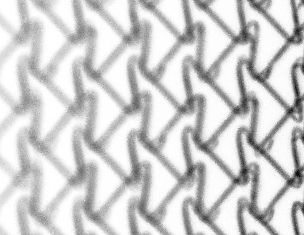
3D PRINTING
the design and fabrication of structures to support plant life at a microscopic level.
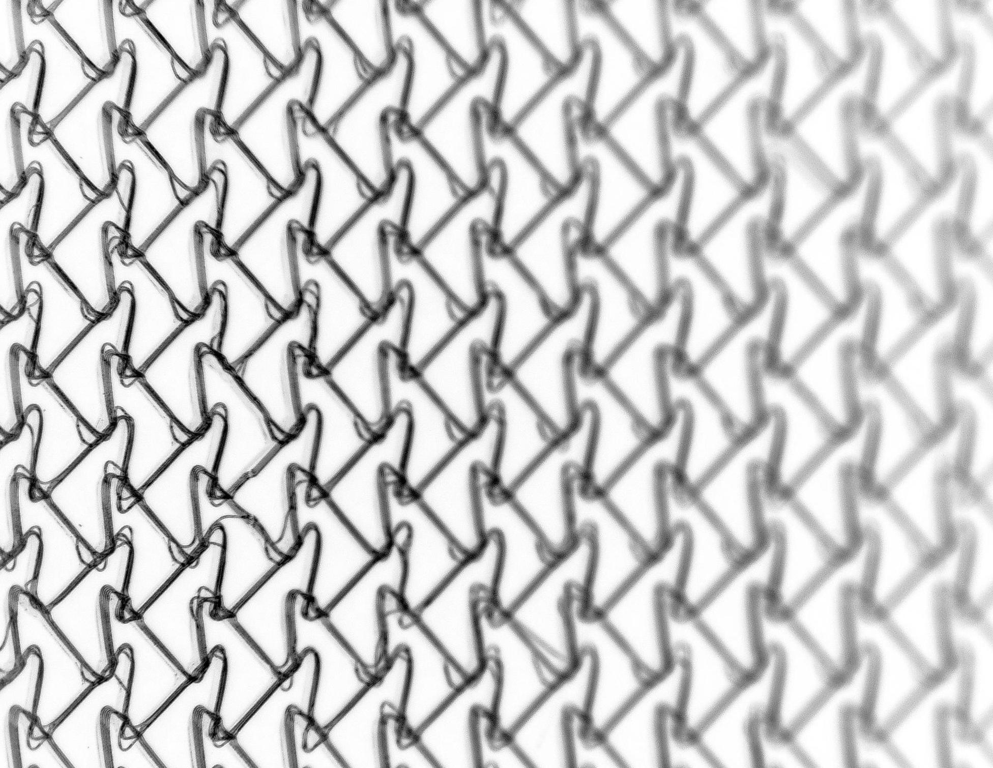
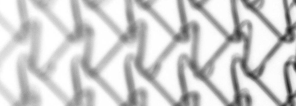
These microscopic scaffolds were designed digitally and fabricated in collaboration with the Dalton Lab at the University of Oregon. Fabrication was completed using melt electrowriting (MEW) 3D printing technology, an innovative technology developed within the last ten years. MEW technology is currently being used by the Dalton Lab to print scaffolds for human cell growth and surgical application. This project explores expanding the application of these scaffolds to plant cells and systems.
This project explores the fabrication limitations and nuances of MEW 3D printing technology. By adjusting the density of lines and speed at which scaffolds are printed, large variations in the results can be created.

IMAGE:
Melt Electrowriting 3D Printer
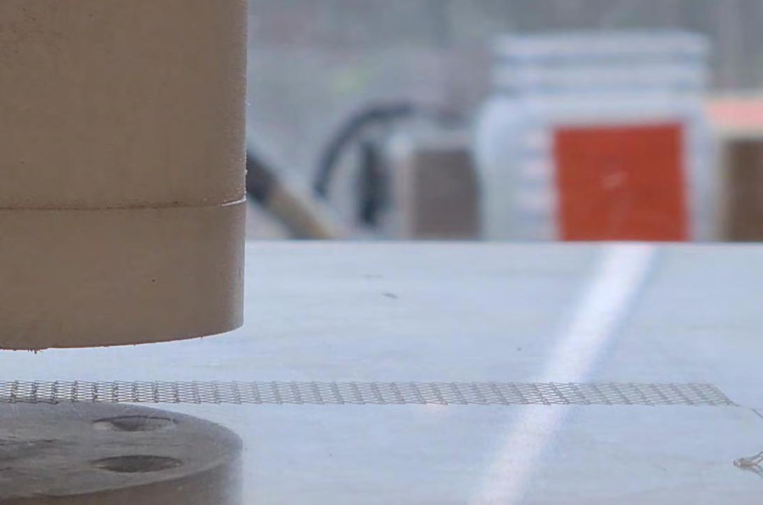
The design and development of scaffolds heavily on digital technology. Patterns were initially designed using Rhino, a 3D modeling software, and Grasshopper, a parametric design plug-in for Rhino. Scaffolds were initially designed as 2D line drawings, and then extruded to mimic the depth of real 3D-printed scaffolds.
The scaffolds for this project were
Many variables were rapidly changed to pursue diverse results.
Chosen scaffolds, presented in the following pages, were selected based on their aesthetic appearance. Growth patterns found in nature served as the inspiration for the scaffold designs.
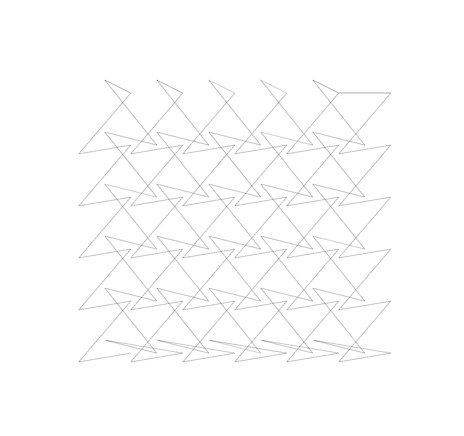
IMAGES:
Scaffold Design Line Drawing (left)
Extruded Drawing (right)
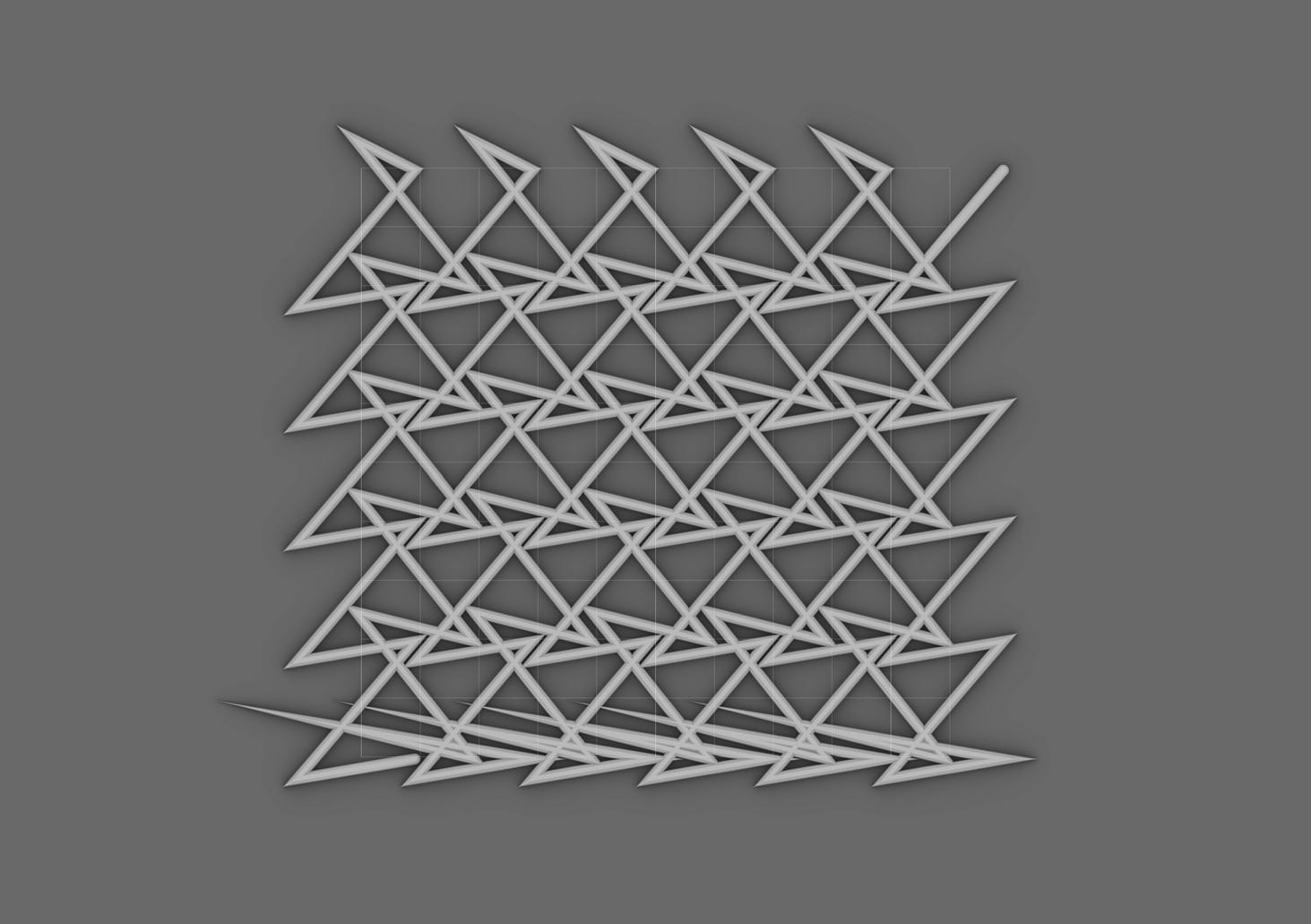
DIGITAL PATTERN STUDY 01
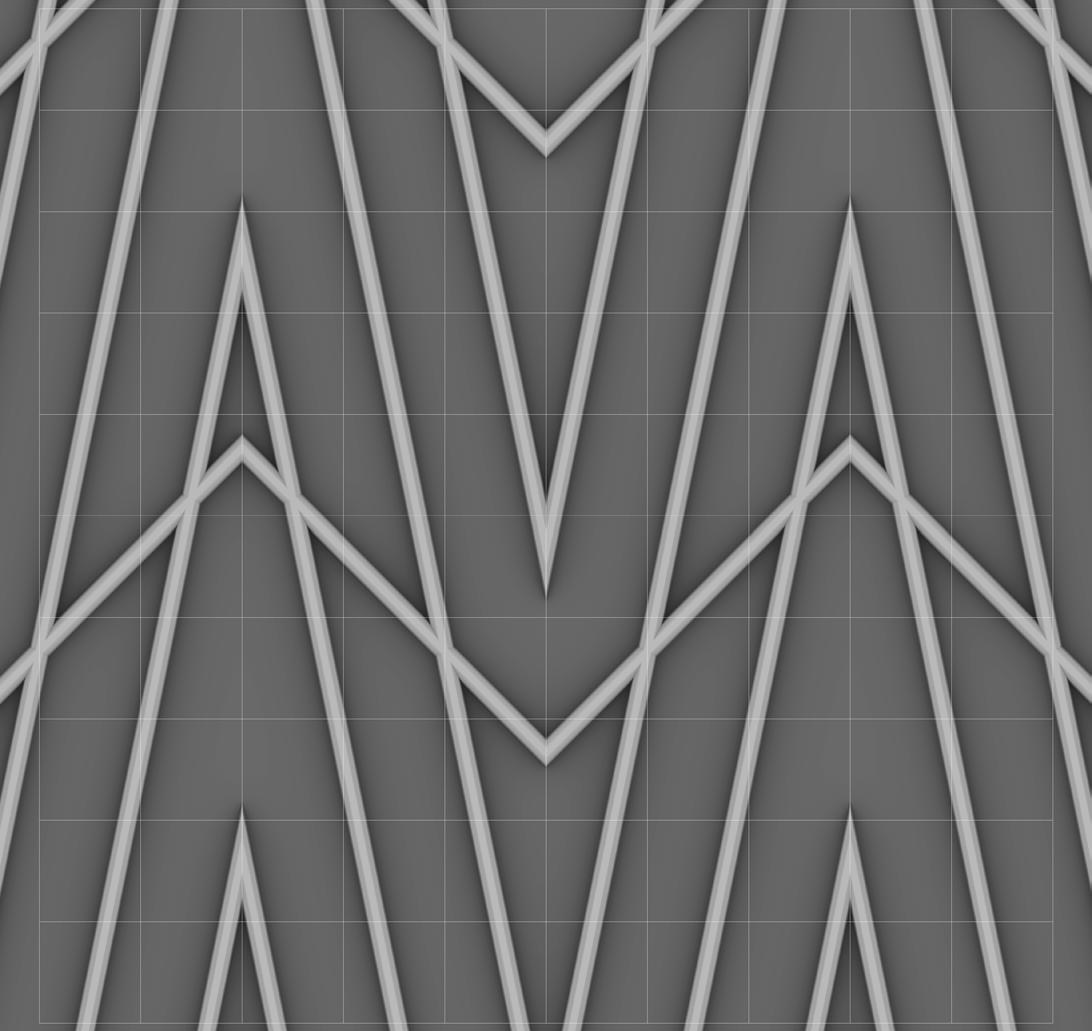
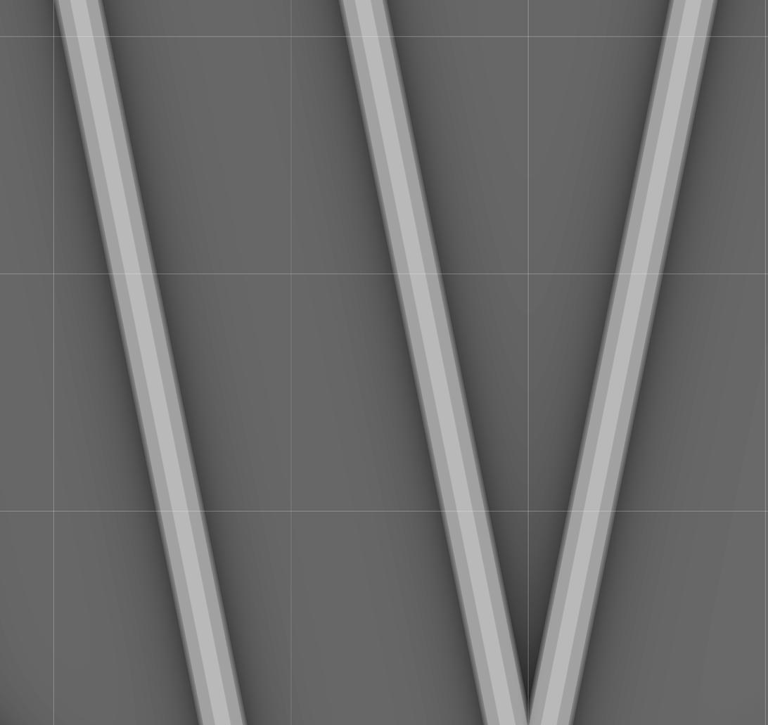
This pattern was an experiment in the scale of voids and density of lines. This pattern is made up of aligned, overlapping rows of points of varying heights. The of sand dunes.
The cell size used in the design of this pattern was 3mm.
The intended speed for this print is F600.
1 mm
IMAGES:
Sand Dune Detail
Field of Sand Dunes


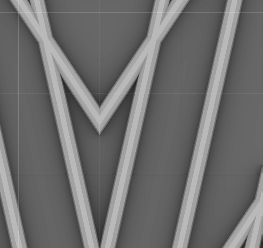
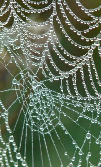
DIGITAL PATTERN STUDY 02
also an experiment in scale of voids and density of lines. This pattern contains rows of points that align at the top, emulating the geometry and construction of a spiderweb. The overlapping lower points in this pattern simulate the appearance of droplets of water.
The cell size used in the design of this pattern was 2mm.
The intended speed for this print is F600.

1 mm
IMAGES:
Water Drops Detail
Water Drops on Spiderweb

DIGITAL PATTERN STUDY 03
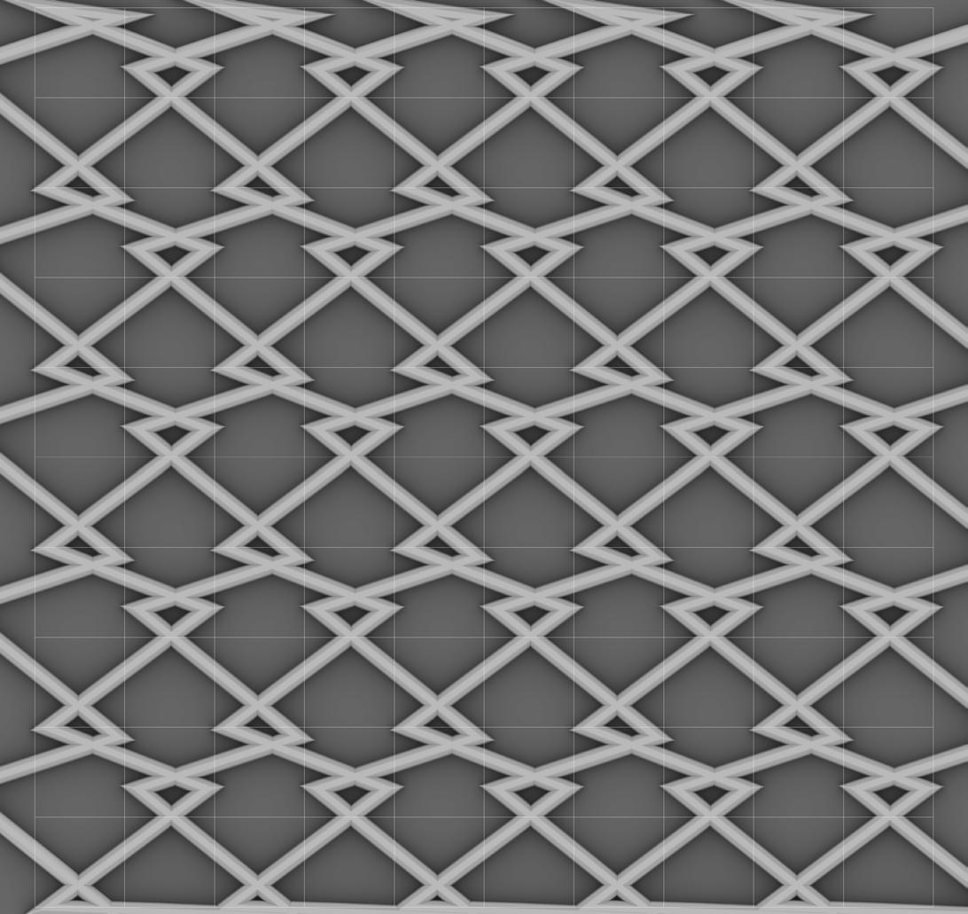
The goal for this pattern was to emulate natural bubble formations that consist of large and small bubbles nestled next to each other. This pattern mimics these bubble formations by creating enclosed voids of varying sizes.
The cell size used in the design of this pattern was 1mm.
The intended speed for this print is F600.
IMAGES:
Bubble Detail
Bubble Cluster 1 mm
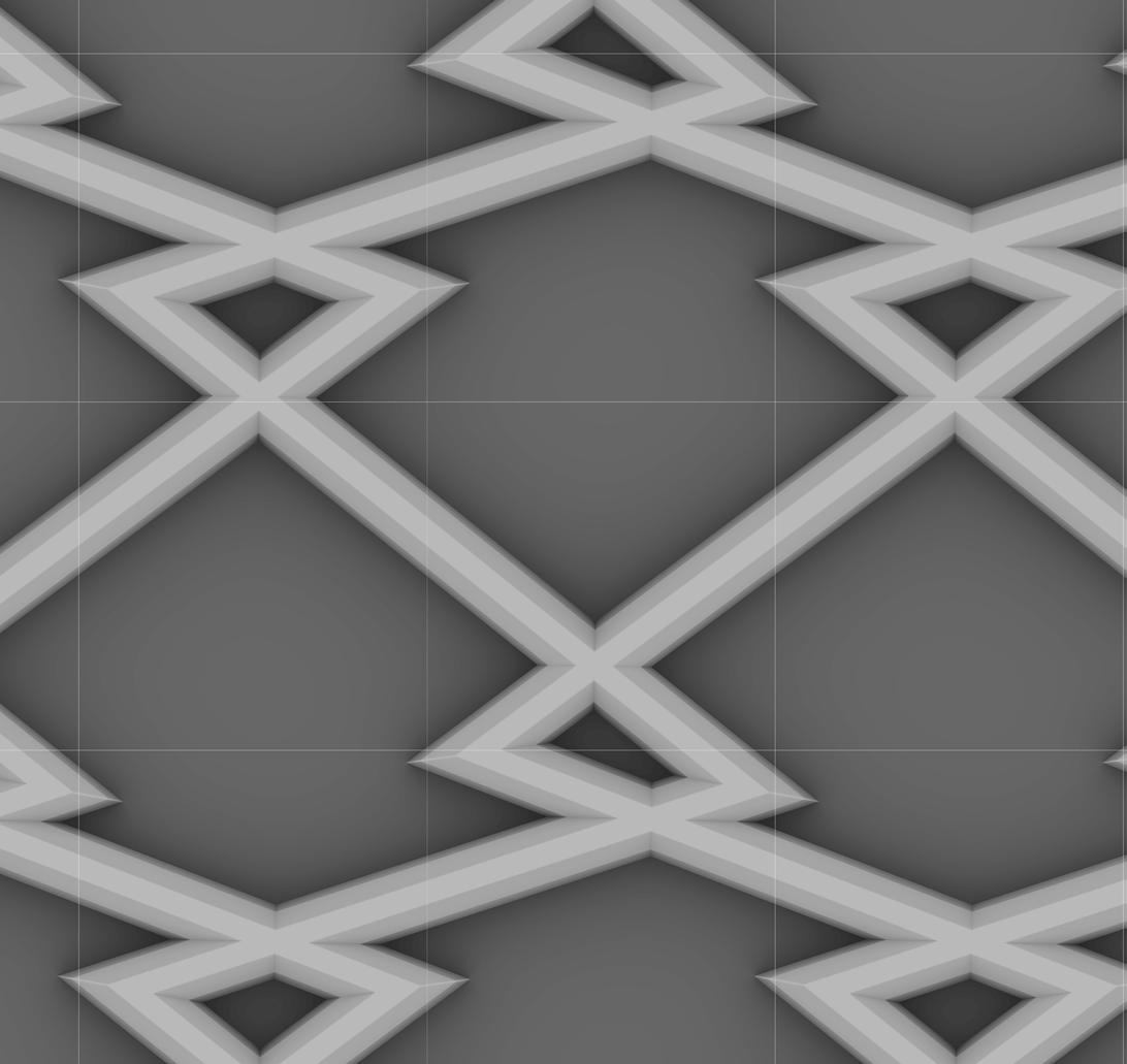


DIGITAL PATTERN STUDY 04
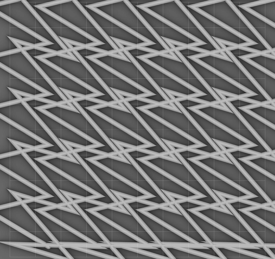
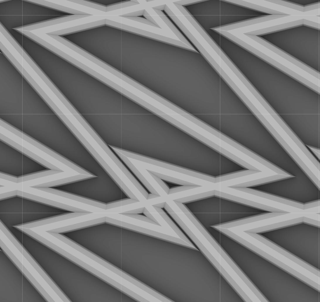
The angular curves of this pattern mimic the sharp geometry found in lightning. The lines in this pattern are concentrated in rows. The tendrils which branch out from each of these central rows mimic the branching tendrils found in lightning.
The cell size used in the design of this pattern was 1mm.
The intended speed for this print is F600.
1 mm
IMAGES:
Branching Lightning Detail Lightning Strike


DIGITAL PATTERN STUDY 05
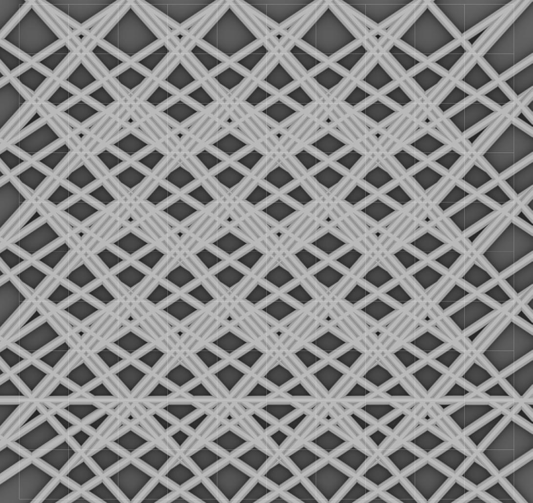
In this pattern, unbroken, regulating lines and voids of similar scales and shapes approximate the natural symmetry found
geometry by emulating its complexity.
The cell size used in the design of this pattern was 1mm.
The intended speed for this print is F600.



DIGITAL PATTERN STUDY 06
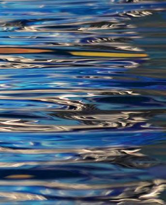
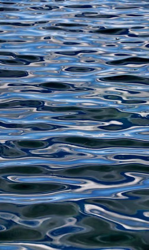
In this pattern, horizontal bands of repeating points emulate ripple patterns found in water. A system of diagonal lines overlaid across these horizontal bands adds a layer of complexity, simulating the irregularities found in natural patterns of ripples.
The cell size used in the design of this pattern was 1mm.
The intended speed for this print is F600.

1 mm

IMAGES: Ripple Details Ripples in Water
DIGITAL PATTERN STUDY 07
This pattern mimics the pattern of leaf growth found in a fern. The angles of the lines in this pattern match the angles at which leaves grow out of the stem of a fern. The rows of repeating lines emulate a fern’s many rows of leaves.
The cell size used in the design of this pattern was 1mm.
The intended speed for this print is F600.
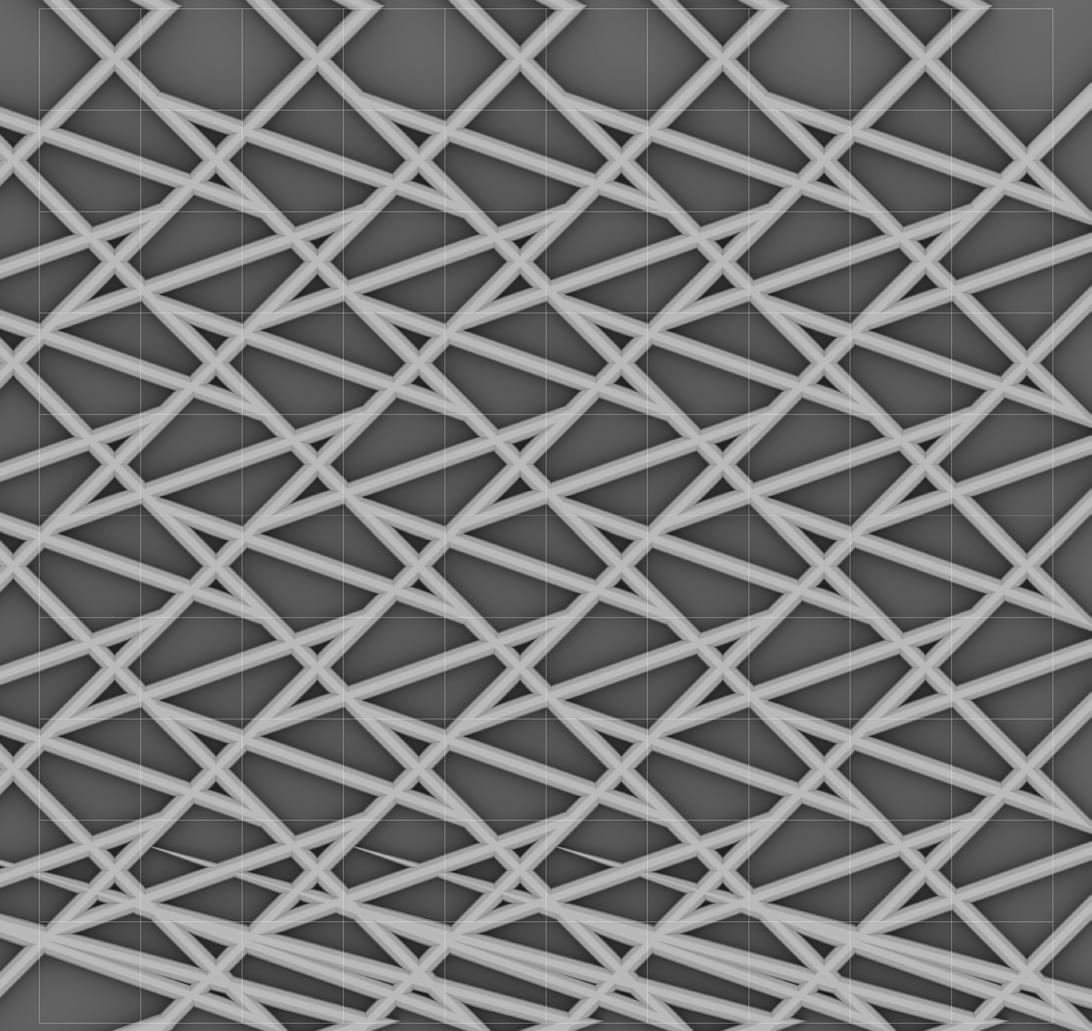
IMAGES: Fern Leaf Detail


DIGITAL PATTERN STUDY 08
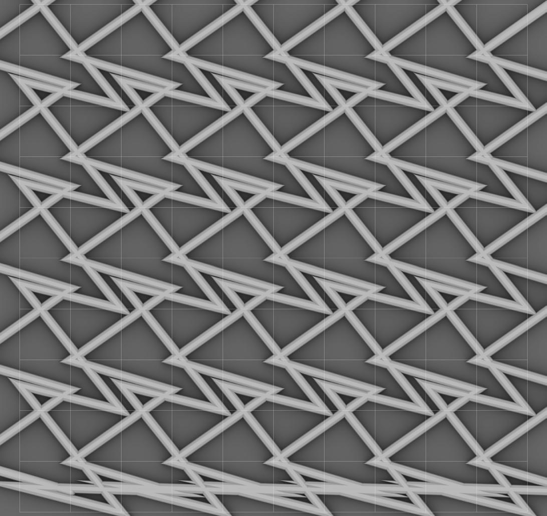
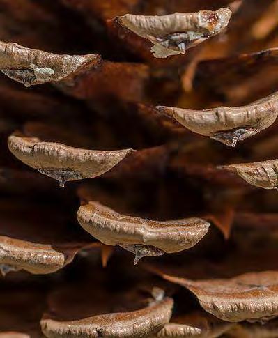
This pattern contains rows of large voids and small voids, emulating the rows of scales that make up a pinecone. The triangular shapes of the pattern’s voids mimic the triangular shapes of the pinecone’s scales and the spaces in between them.
The cell size used in the design of this pattern was 1mm.
The intended speed for this print is F600.
1 mm


DIGITAL PATTERN STUDY 09
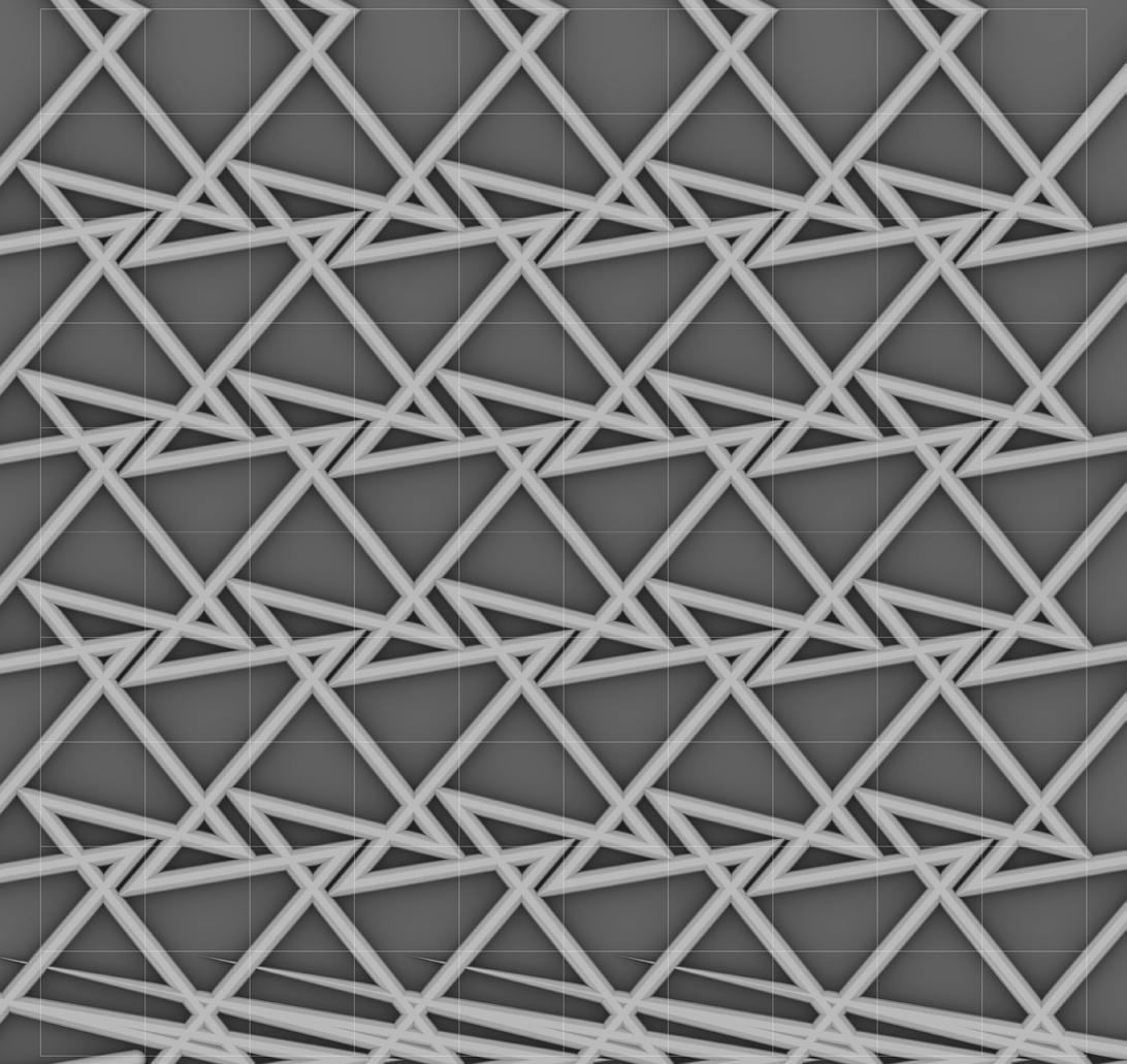
The aim of this pattern was to imitate the shapes created by the Voronoi pattern, a mathematical pattern that occurs throughout nature and can be seen on the skin of a giraffe. This pattern mimics the varied polygons of the Voronoi pattern by incorporating voids of four different shapes and sizes.
The cell size used in the design of this pattern was 1mm.
The intended speed for this print is F600.
1 mm

IMAGES:
Giraffe Pattern Detail Pair of Giraffes


DIGITAL VS. FABRICATED
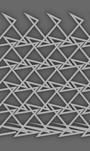
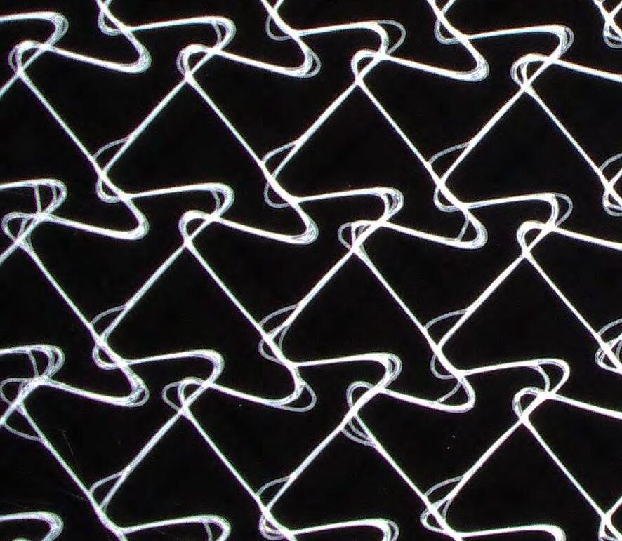
Of all the patterns developed in the digital pattern studies, Pattern 09: Giraffe was selected for fabrication and continued development.
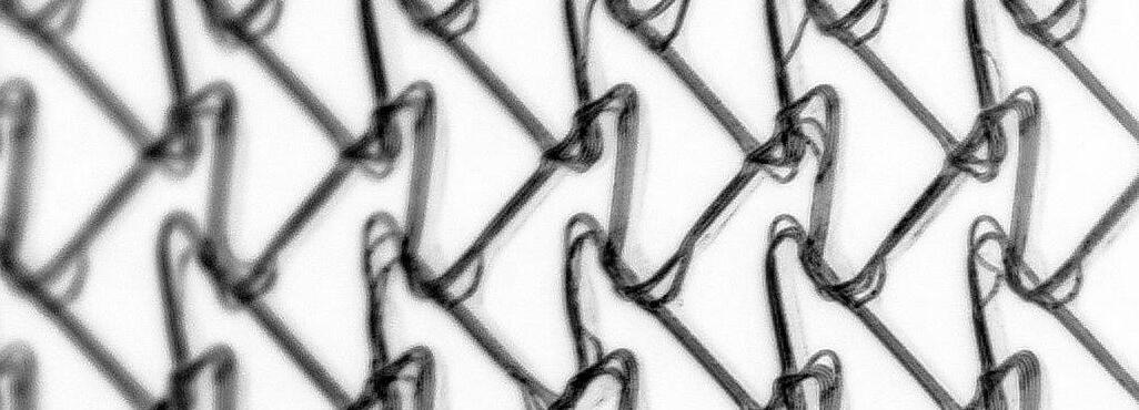
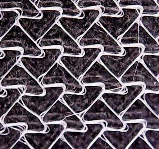
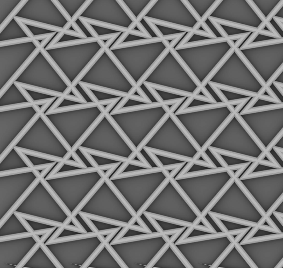
A test print of this pattern generated a design that lacks the angular overlapping points of the original design but has a consistent symmetry. Printing this pattern created an offset layering of strands at points where the printer changed directions, adding a beautiful detail to the pattern.
The speed for this print was F600.
Because of the pleasing aesthetic result of this test print, this same design was used fabrication.
Body Copy
1 mm
IMAGES:
Test Printing Result (left)
Digital Pattern Design with Test Print Overlay (right)
PATTERN 09: GIRAFFE
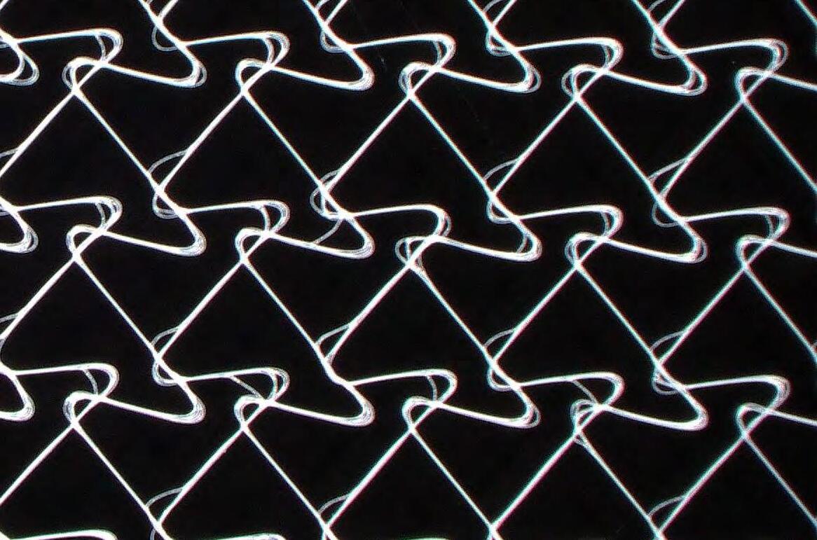
scaffold. This scaffold was printed with more modules than previous test prints.
DIGITAL FABRICATION VARIATION
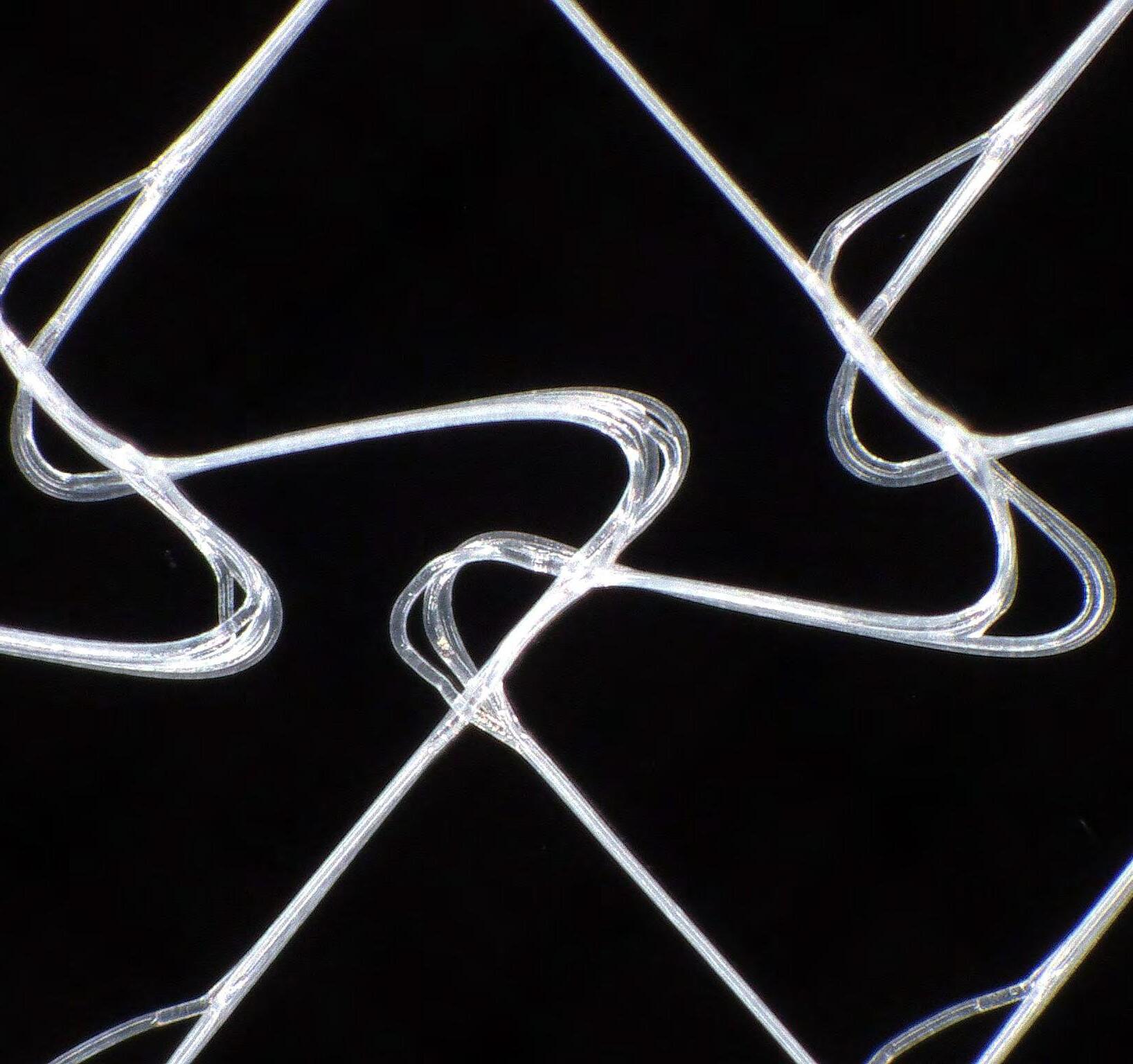
print revealed a natural variation in the overlap. These variations are a result of the fabrication process and are not included in the original computerdesigned linework, which is noticeably regular. These subtle variations add mimicking the variation found in nature.

Variation in 3D Printed Scaffold Details
IMAGE:
NATURAL SYSTEM INTEGRATION
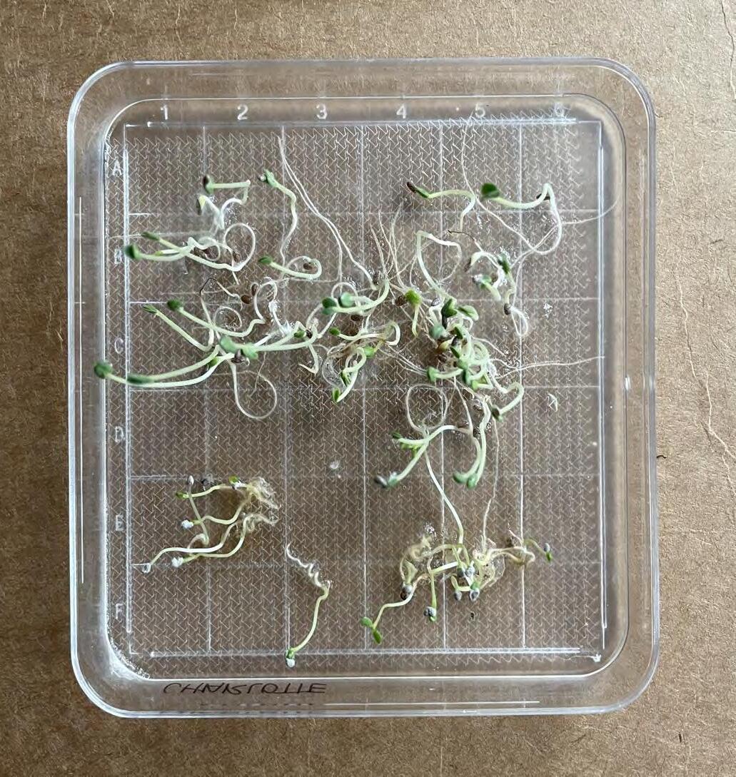
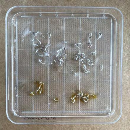
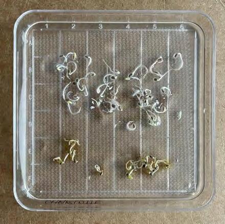
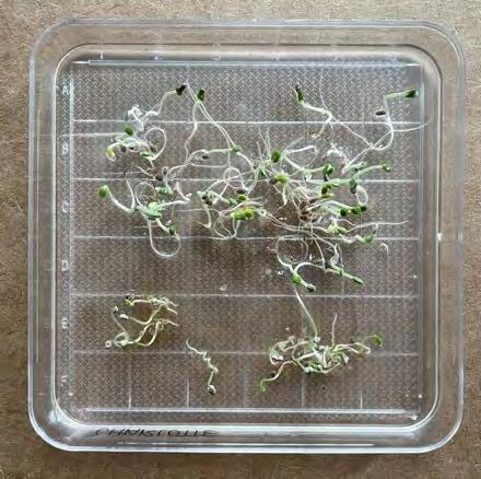
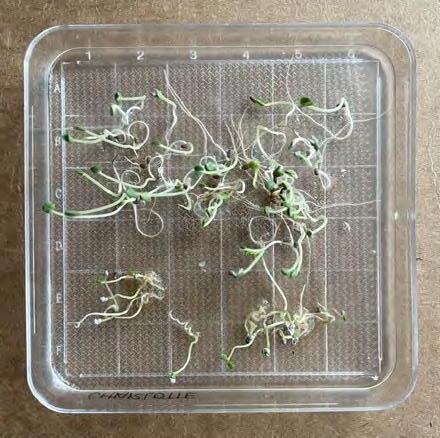
To examine how plants interact with the scaffold design, a test print of the scaffold was submerged in a transparent nutrient gel. Chia (top) and Clover (bottom) seeds were then planted and watered daily.
their growth progress was tracked over a series of multiple days. (See images on facing page.)
The plants’ root structures grew on top of the scaffold in relatively straight lines. The minimal interaction between the plant root systems and the scaffold suggests that a scaffold of a different cell size or thickness would likely be more appropriate for facilitating plant interactions. It is hypothesized that a thicker scaffold with a larger opening size would be able to better intercept and impact root growth formations.
IMAGES:
Chia and Clover Growth Over Time




Phase II of this project explores the design of an installation to support plant life at the scale of a wall or ceiling assembly.
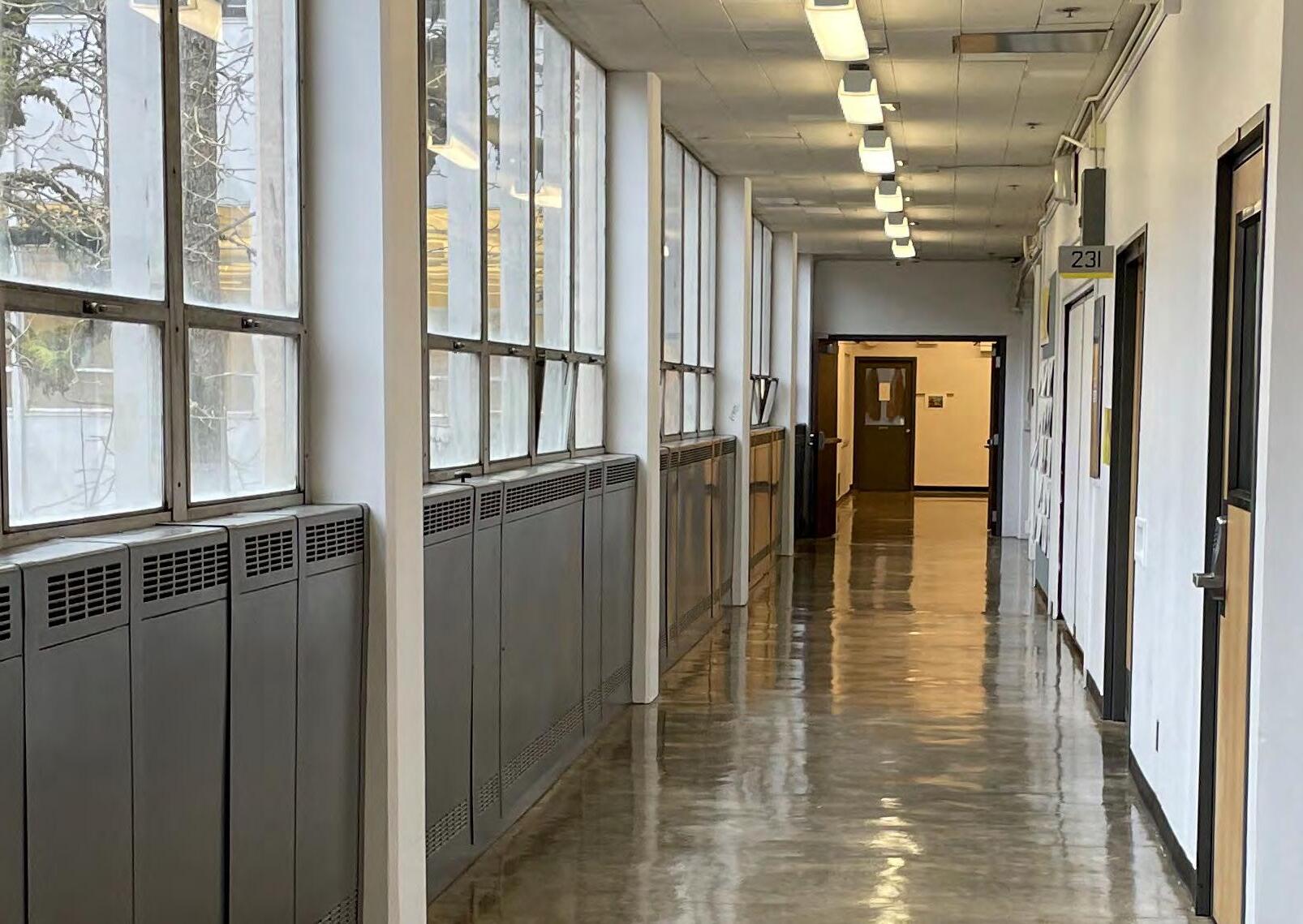
To complete this phase, a case study location was chosen in Lawrence Hall, the home of the School of Architecture and Environment at the University of Oregon. An existing location was chosen to facilitate the study of how to integrate the systems needed to support plant life into an exiting network of mechanical systems.
side of Lawrence Hall’s central courtyard was chosen as the theoretical location for an installation of plant life. This hallway was chosen because of its large window array, which provides plenty of indirect natural light to the interior space. This hallway was also chosen for the large array of radiant heaters located beneath the windows. These heaters maintain the hallway temperature, but detract from the aesthetics of the hallway and indicate poor insulation of the window assembly. Removal of these heaters would provide room for a planted installation with the potential to improve environmental conditions and aesthetics without changing the amount of usable space in the hallway.
LAWRENCE HALL, UNIVERSITY OF OREGON
SECOND FLOOR N
DIGITAL MODEL OF EXISTING CONDITION, LAWRENCE HALLWAY
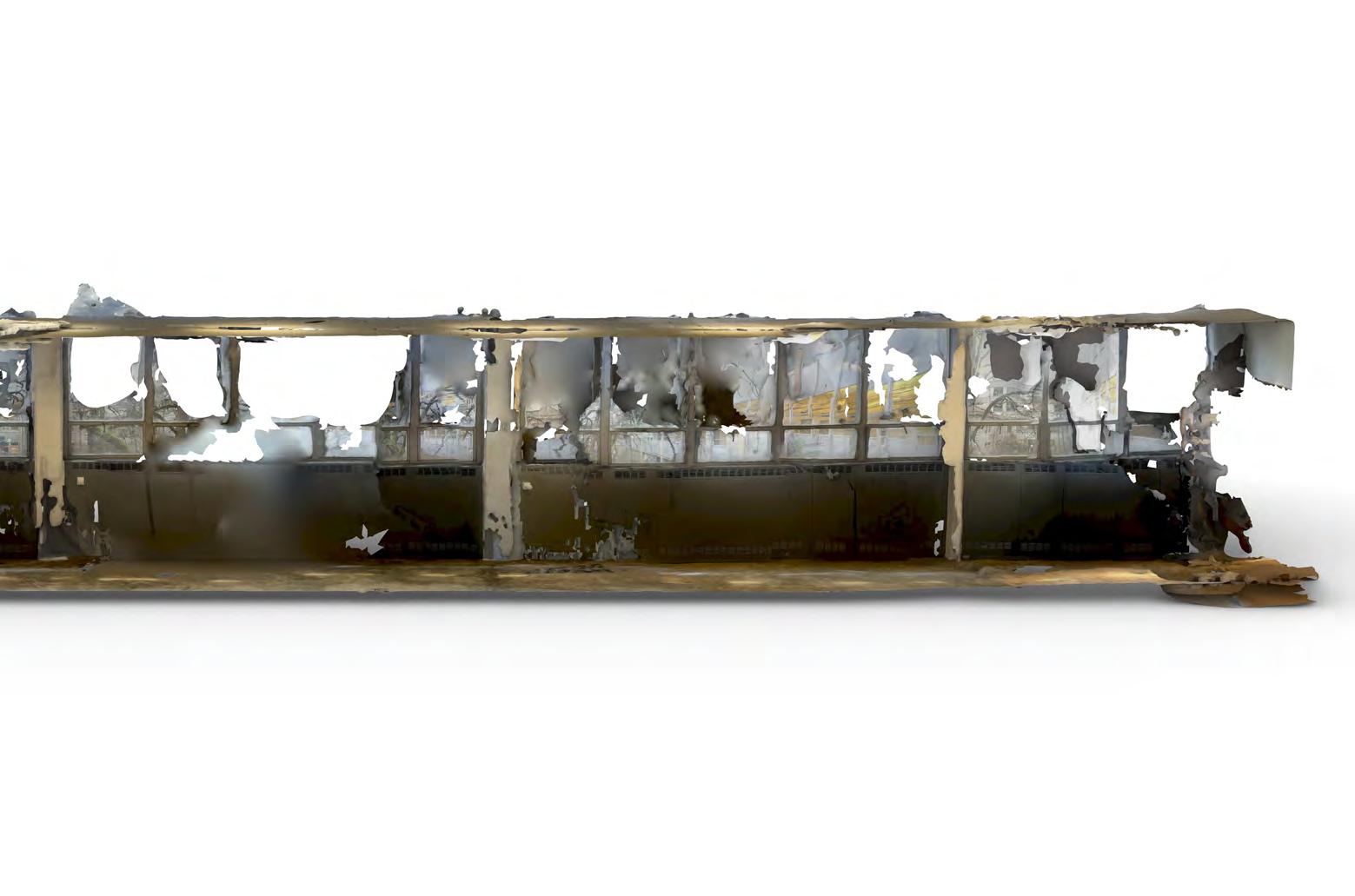
Early attempts to build a model of the existing hallway space employed photogrammetry. Photogrammetry is a process that builds a digital model from photographs. A sequence of photos are taken of a space or object and then input into a computer program, which uses the graphic and geographic location stored in the photographs to build a model.
Attempts to use photogrammetry to build an accurate model of the west hallway on largely a failure. The camera and software seen through the hallway’s windows from the foreground. This resulted in a model that is warped and choppy. This model is pictured here and on the next pages.
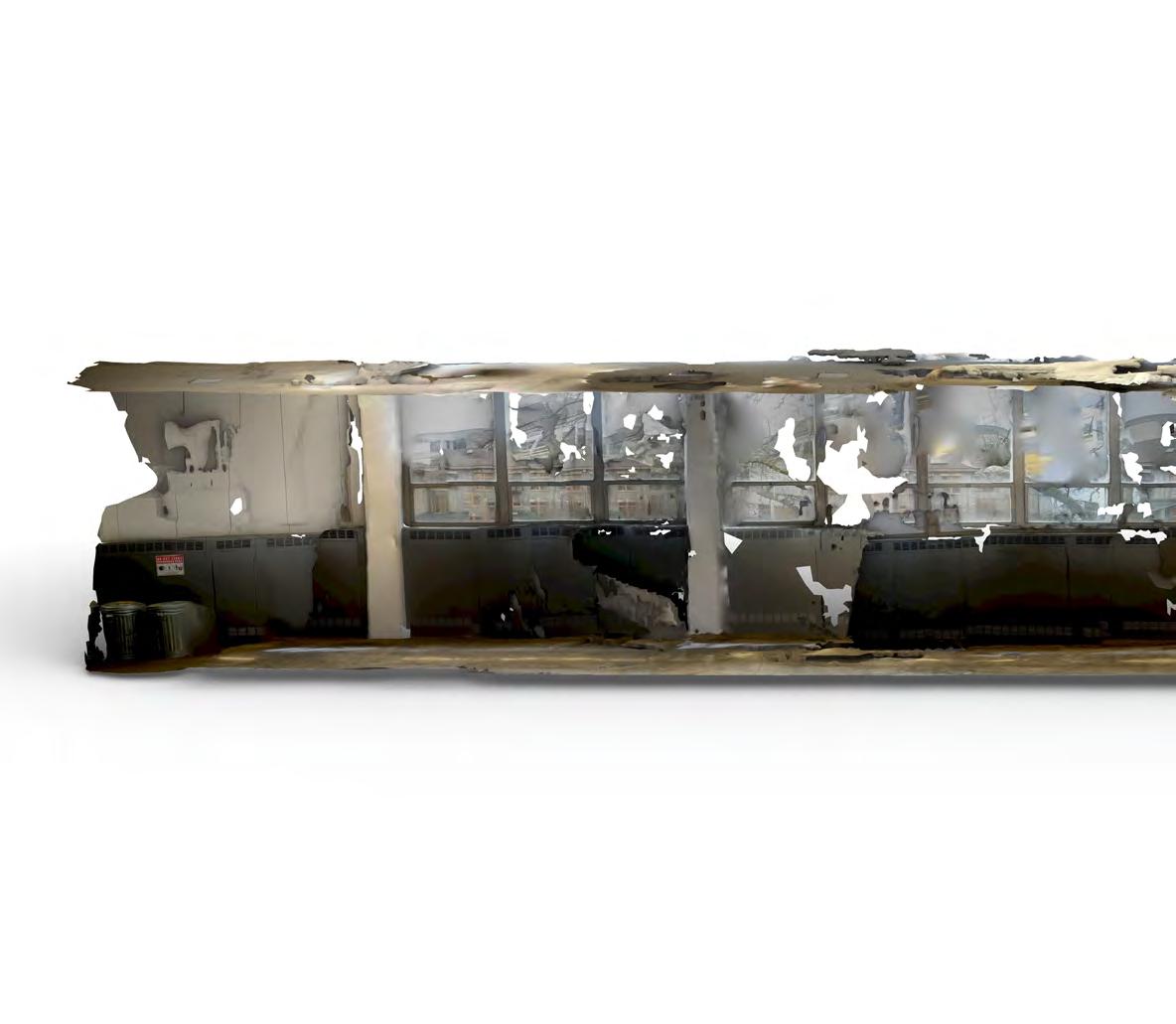
IMAGE:
Distorted and Inaccurate Photogrammetry Model
DIGITAL MODEL OF LAWRENCE HALLWAY

IMAGES:
Distorted and Inaccurate Photogrammetry Model

Because photogrammetry failed to produce an accurate model of the hallway, other methods were used to generate a digital replica of the space. Measurements taken on site were used to manually build a 3D digital model of the space. This model was then used as a tool to analyze the existing condition of the hallway and design an installation.
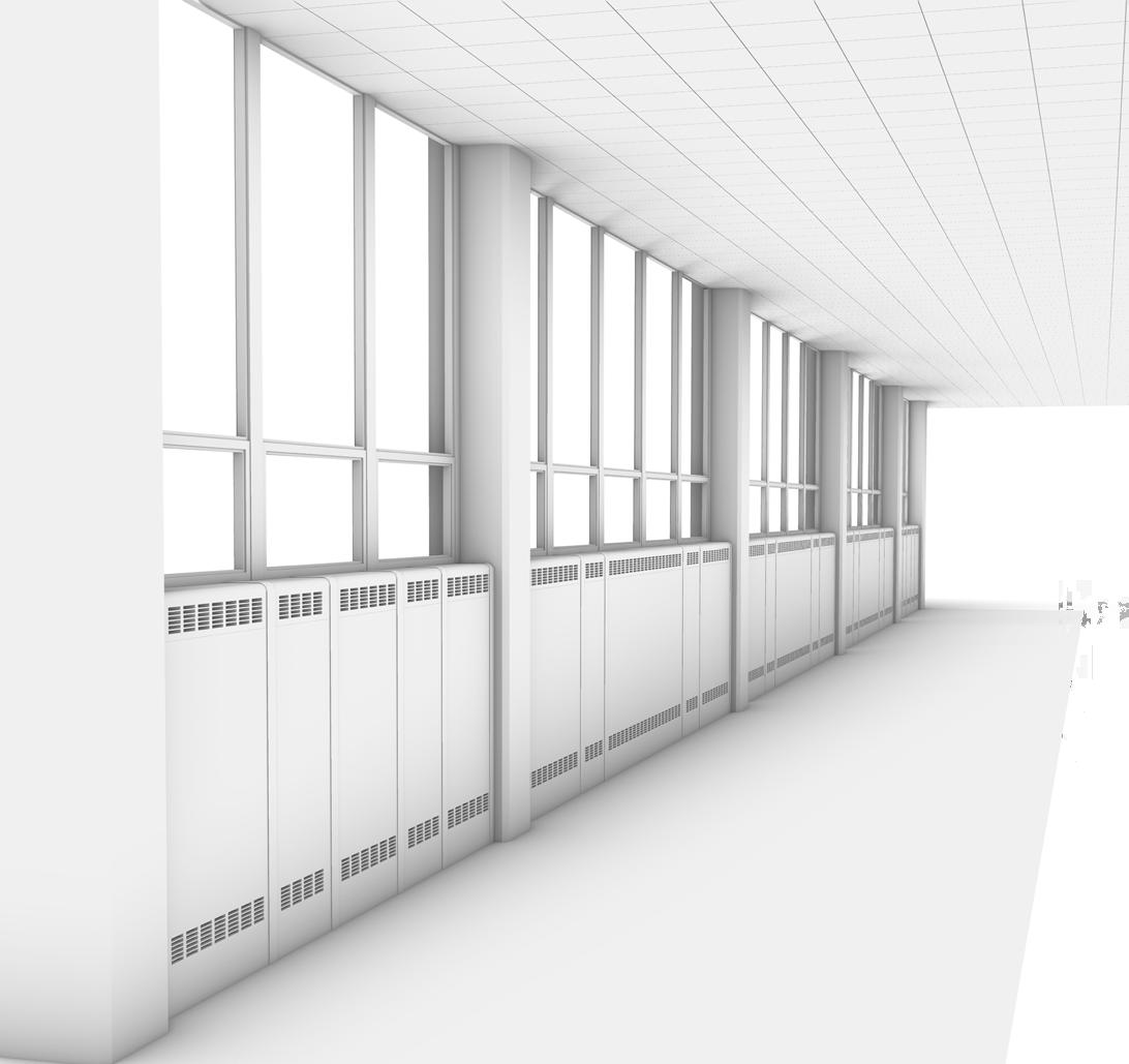
IMAGE:
Geometrically Accurate Digital Twin of Hallway
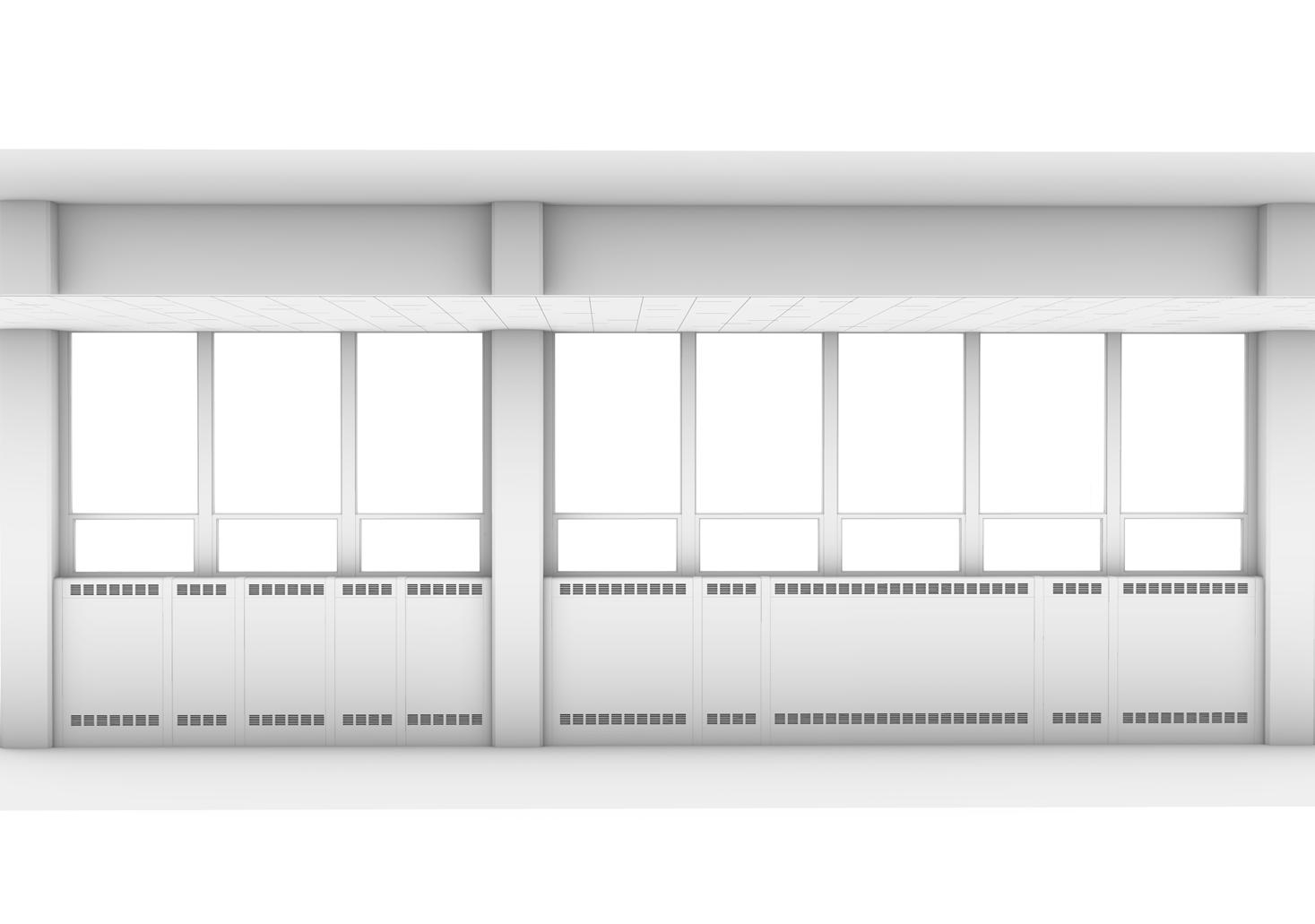
of Lawrence Hall contains an array of windows facing an eastern courtyard. On the west side, this hallway provides access to a series of classrooms. The hallway is a major circulation route to these classrooms and throughout the building.
The courtyard-facing wall of the hallway between columns. These window bays are either three windows wide (“Module
These modules are arranged in the pattern A B B B A, with the shorter window bays located at either end. Further analysis and design of this wall of windows will focus on a single Module A and a single Module B, with the understanding that these hallway.
EXISTING CONDITION, LAWRENCE HALLWAY
The existing hallway contains a dropped ceiling above which the mechanical systems are run. This ceiling hides these systems from occupants of the hallway. Analysis of existing plans of Lawrence sprinkler system, and electrical system are located above the dropped ceiling. Additional conduit, likely used to provide data or Internet to the classroom spaces, is located just below the dropped ceiling. Radiant heaters located along the wall of windows connect to the University of Oregon’s steam heating system.
There is no access to potable water or plumbing in this hallway, as these utilities are only run in other parts of the building. This means that a planted installation, which requires access to water, must either include lengthy connections to other sprinkler system. While connection to the use is illegal, this theoretical project will explore this option.
EXISTING STEAM SYSTEM HEATS HALLWAY AND INSULATES OLD WINDOWS
MECHANICAL SYSTEMS OCCUPY SPACE OVER DROPPED CEILING IN HALLWAY
A FIRE SPRINKLER SYSTEM PROVIDES THE ONLY ACCESS TO WATER IN THIS PART OF THE BUILDING
EXISTING CONDITION, LAWRENCE HALLWAY

Existing Mechanical Systems (For clarity, the dropped ceiling is not shown)
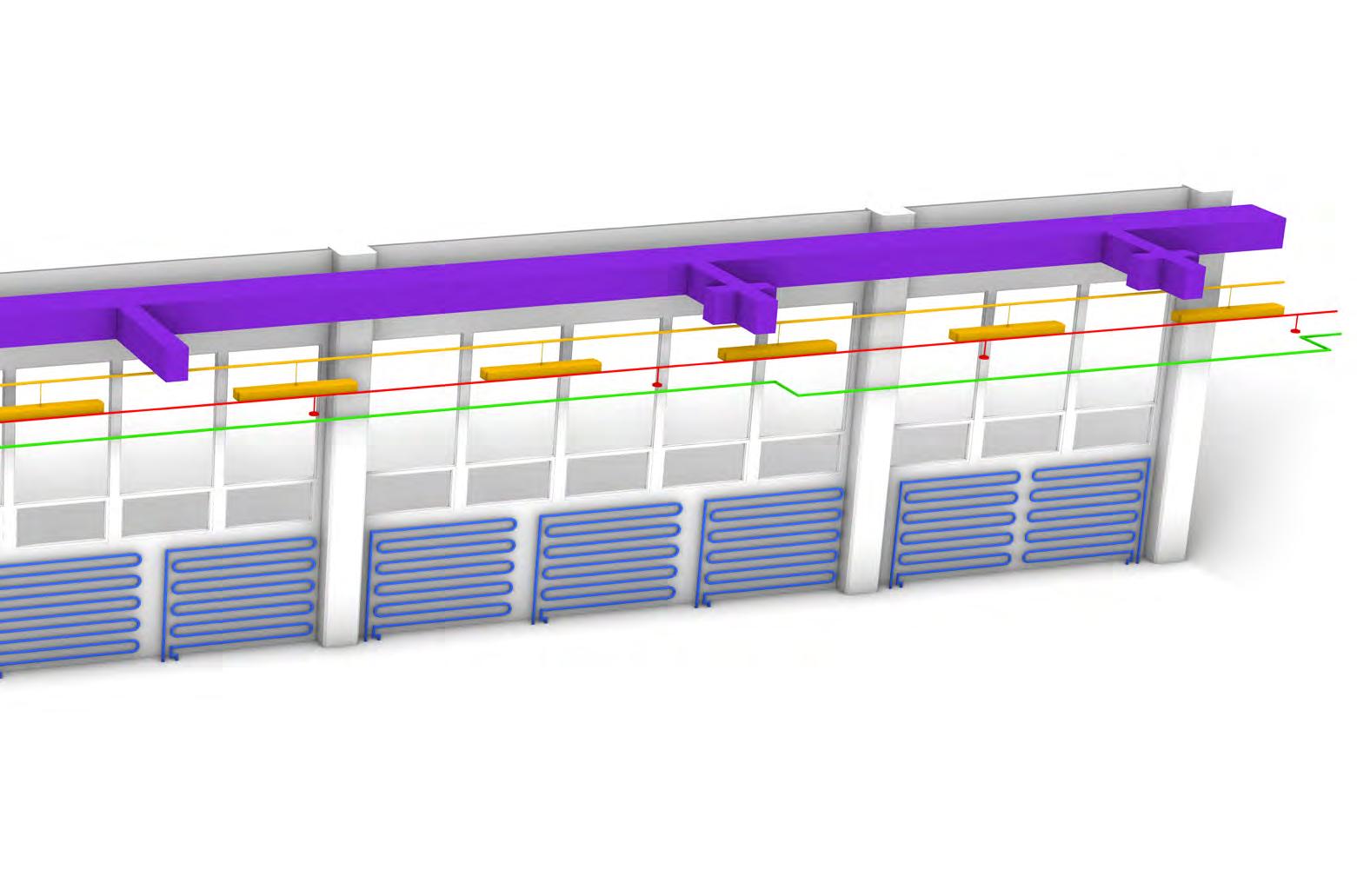
EXISTING CONDITION, LAWRENCE HALLWAY
A dropped ceiling currently hides the existing mechanical systems in this hallway from view.
This project will explore how exposing and redesigning the mechanical systems can activate the ceiling plane in this hallway, making it a beautiful focal point of the space.
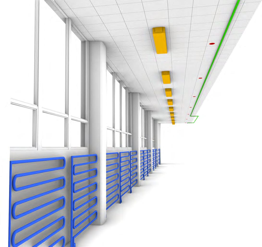
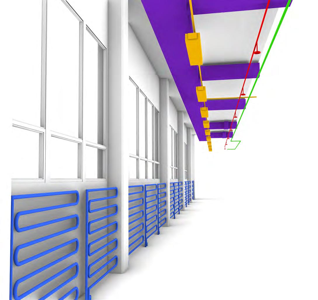
IMAGE:
Existing Mechanical Systems, dropped ceiling shown (left)
Existing Mechanical Systems, dropped ceiling not shown (right)
DATA
EXISTING CONDITION, LAWRENCE HALLWAY
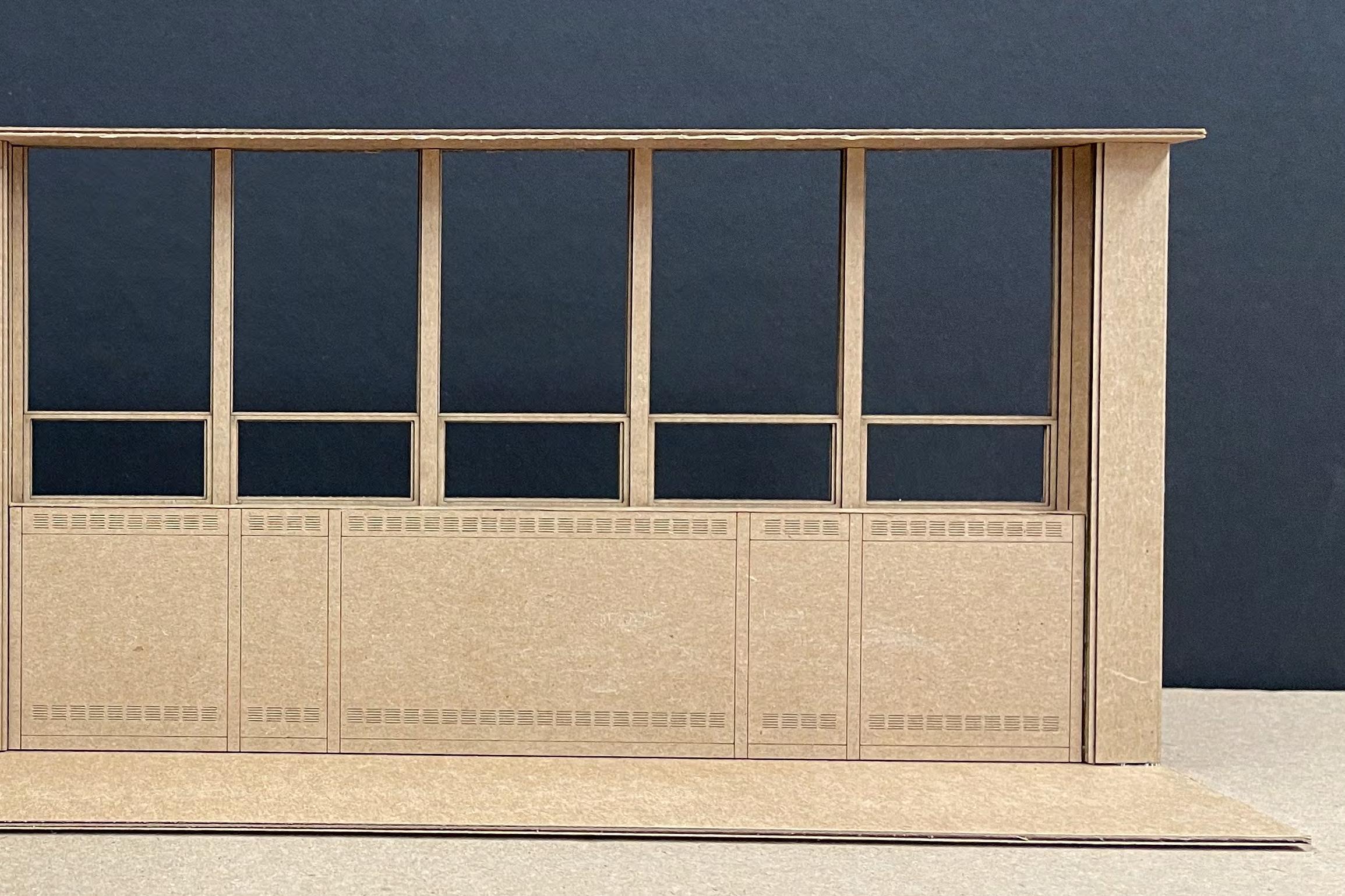
A physical model was created to facilitate a deeper understanding of how the existing wall assembly in the hallway was constructed. This model was built so that the heaters can be removed, leaving empty space under the windows that
This model shows the two modules, A and B, that are repeated to create the entire wall assembly.
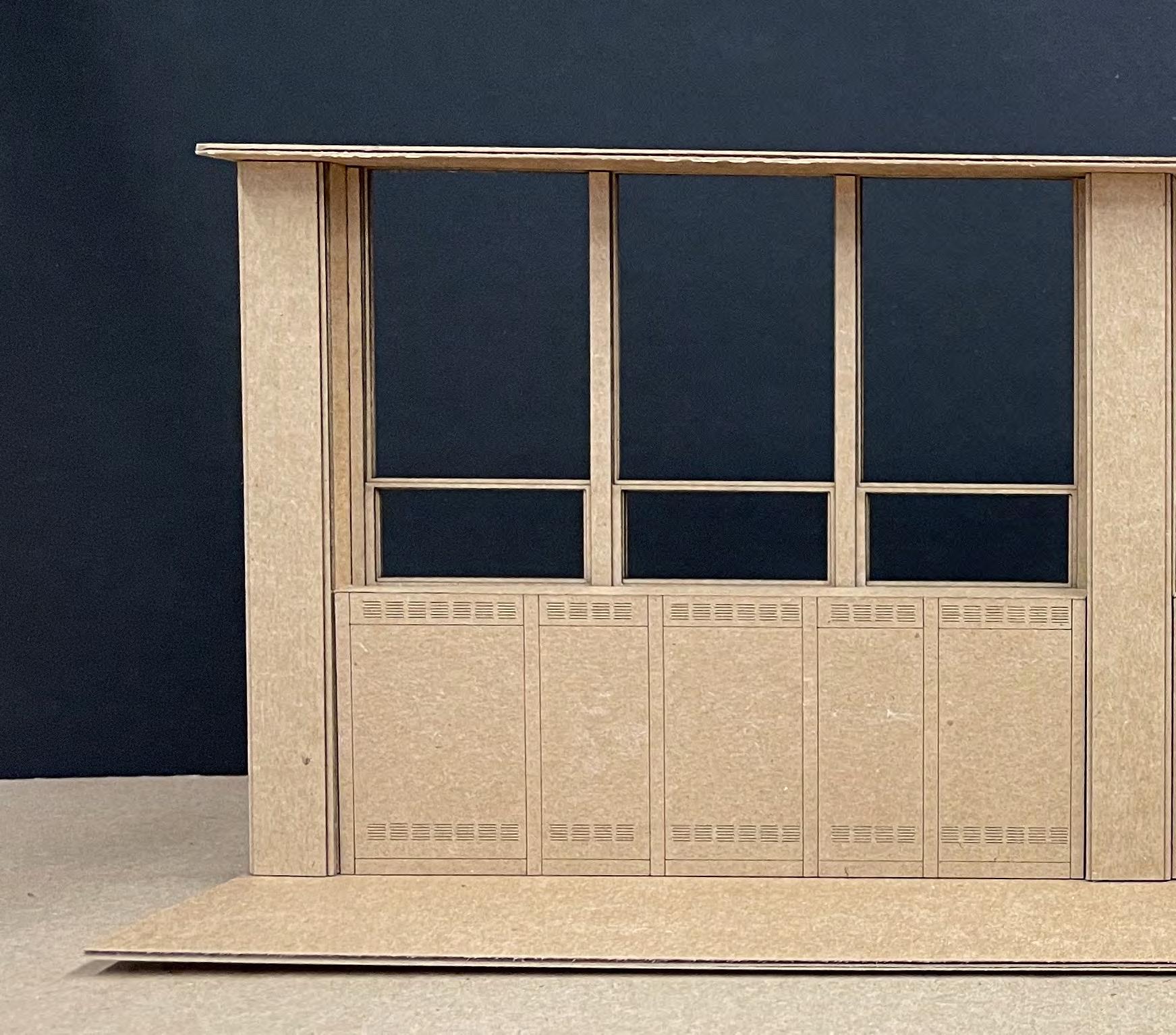
MODULE “A”
WINDOW BAYS
MODULE “B”
STRING AND PEGBOARD
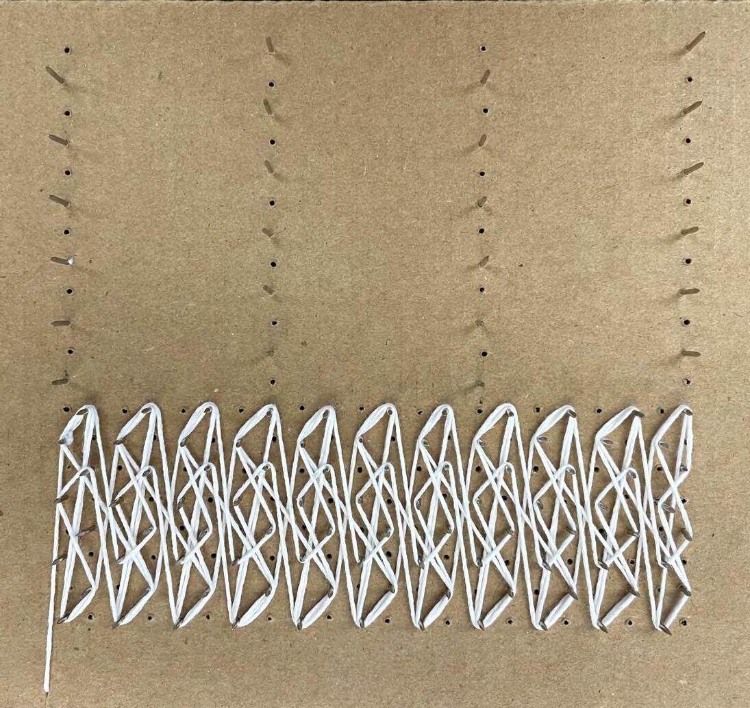
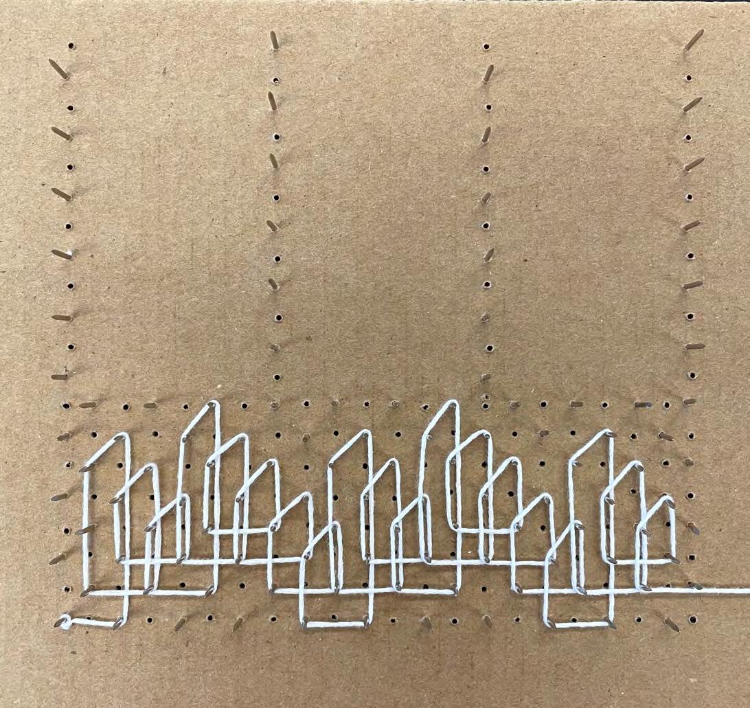
A series of studies completed with string and a pegboard were used as a starting point to design the form of the hallway installation.
The use of string for these studies facilitated the exploration of different repeating or systematic patterns. This repetition was desired because the goal for the eventual installation was a design that could be created out of a small number of repeating components.
The spacing between pegs in the pegboard is six inches. This spacing was set with the intention that components used to eventually build the installation would be roughly six inches long.

Pattern Study Chosen for Development as Installation

STRING AND PEGBOARD
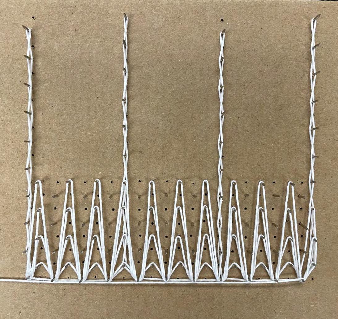
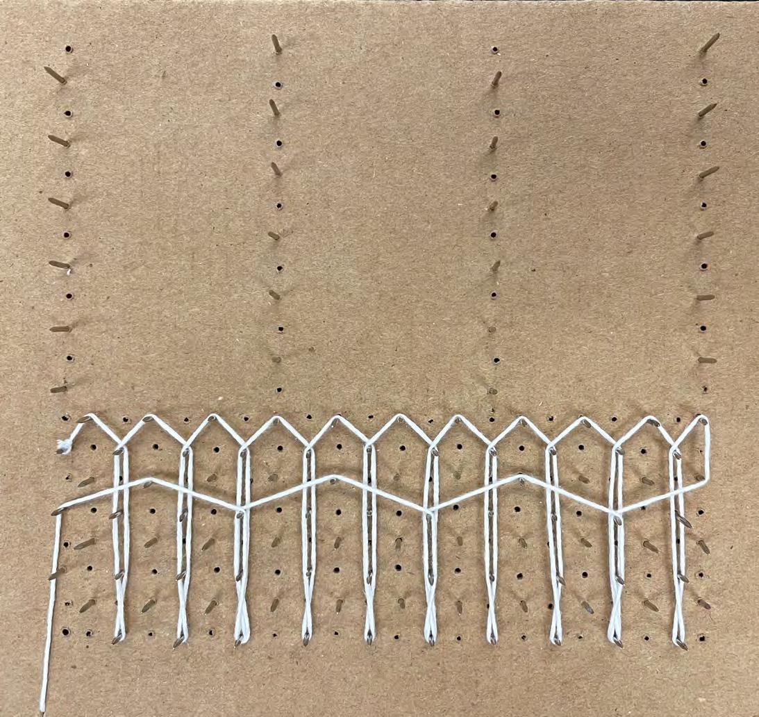
These two studies explored bilateral symmetry around a central vertical axis.

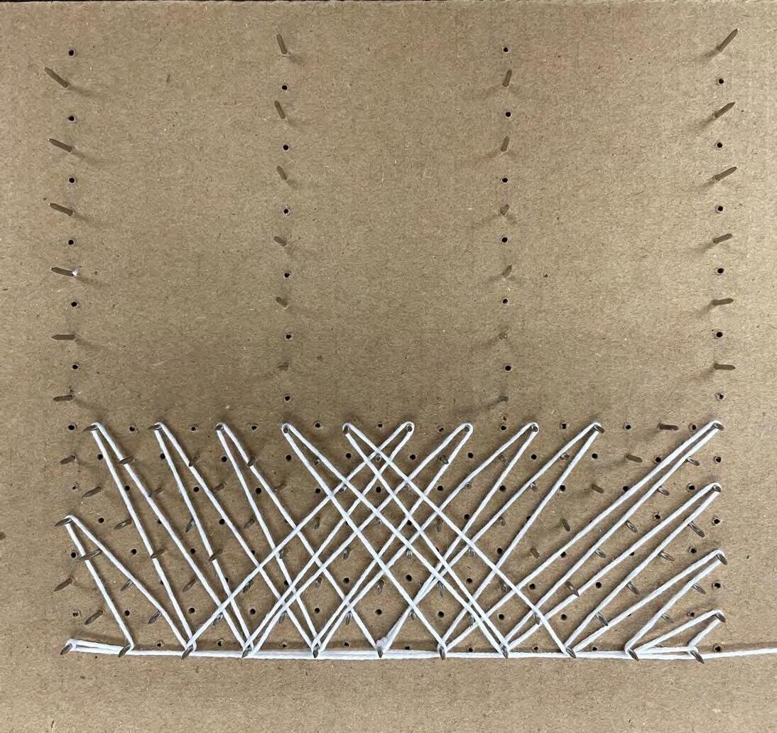
STRING
One study explored the potential for an installation to extend up between windows. The pegboard used for these studies left empty space for windows. This space was left with the intention that the installation would go around the windows to maintain maximum light coming into the hallway.
STRING AND PEGBOARD
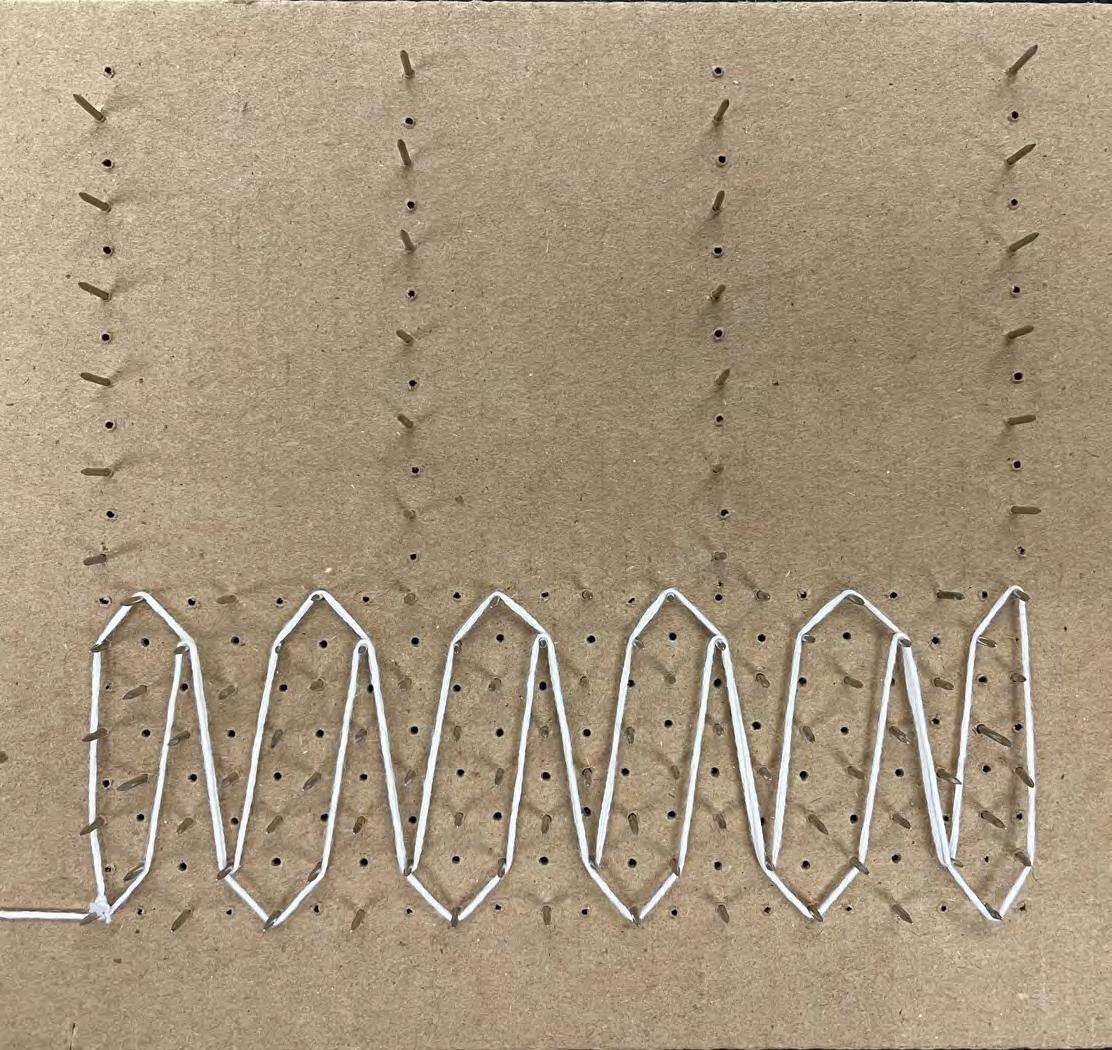
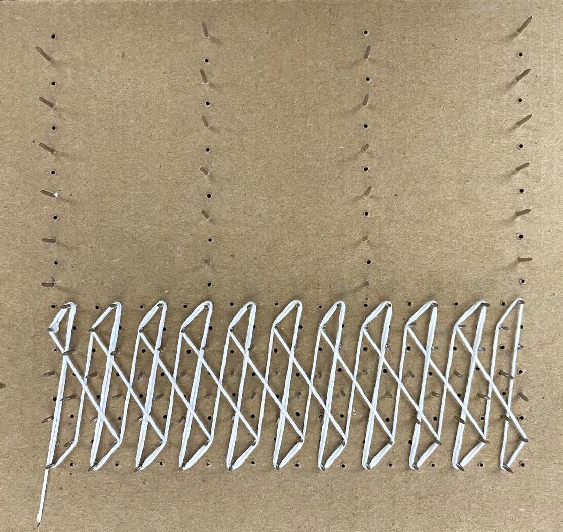
Some studies explored a low density of lines, while other explored higher densities.
STRING AND PEGBOARD
Studies with a very high density of lines were not chosen for development as these patterns would require many different components for fabrication, as well as a very high density of components.

STRING AND PEGBOARD
The most successful pattern studies were those that implemented an asymmetrical repetition. This repetition created designs that could be easily broken down into modular components for fabrication. Additionally, these patterns could be easily scales up from three-window bays aesthetic character of the pattern.
Pattern Study 10 (right) was chosen
installation design. This pattern was chosen because of its asymmetrical repetition and resemblance to Voronoi patterns made up of polygons of various sizes.

DIGITAL MODULE DEVELOPMENT AND PATTERN DESIGN
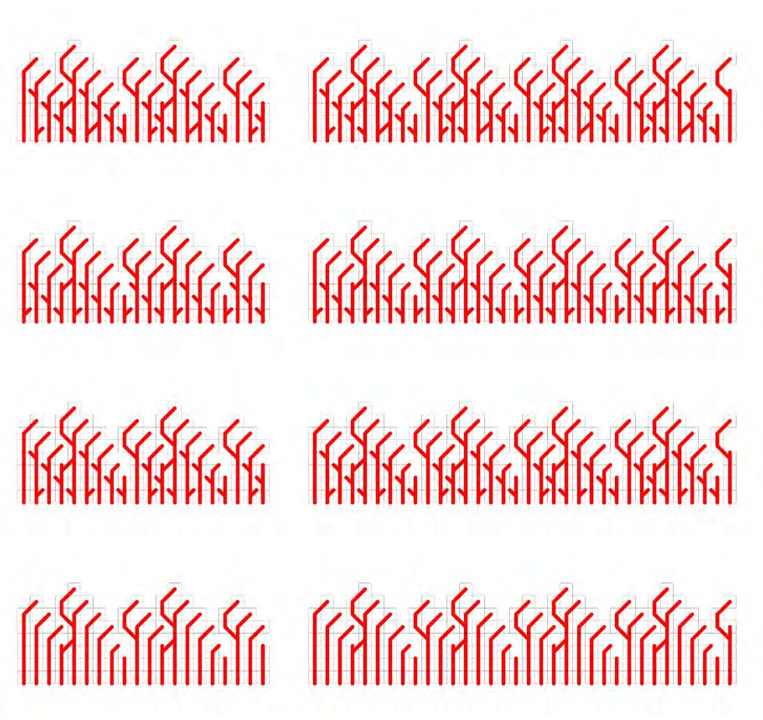
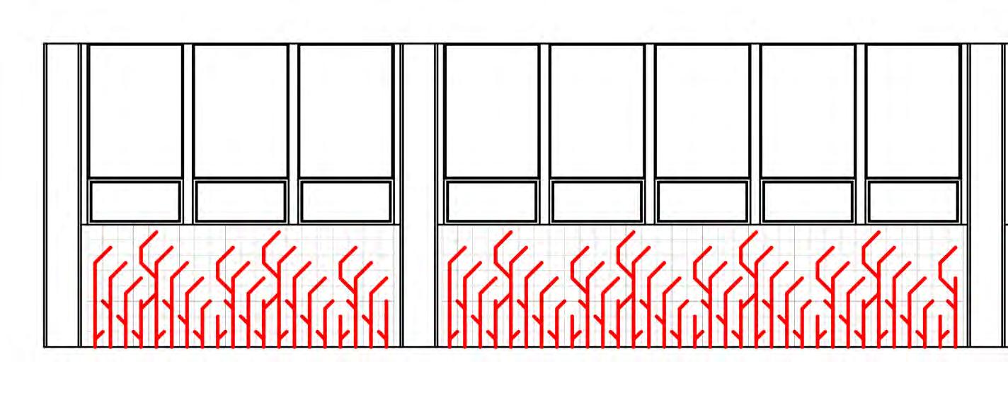
Development of the design for the installation was completed digitally.
size of thee windows, the design was
then developed at once.
Modular components were developed based on Pattern Study 10, which was completed with string on the pegboard. Components were arranged to mimic the initial pattern study. Components were then exchanged and added until the design reached the desired level of complexity.
IMAGES:
Modular Components & Final Design Developed Installation Design

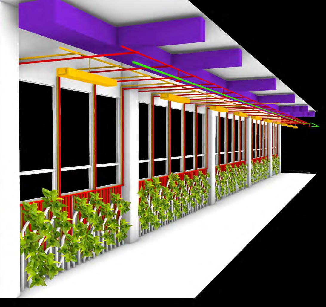
INITIAL DESIGN
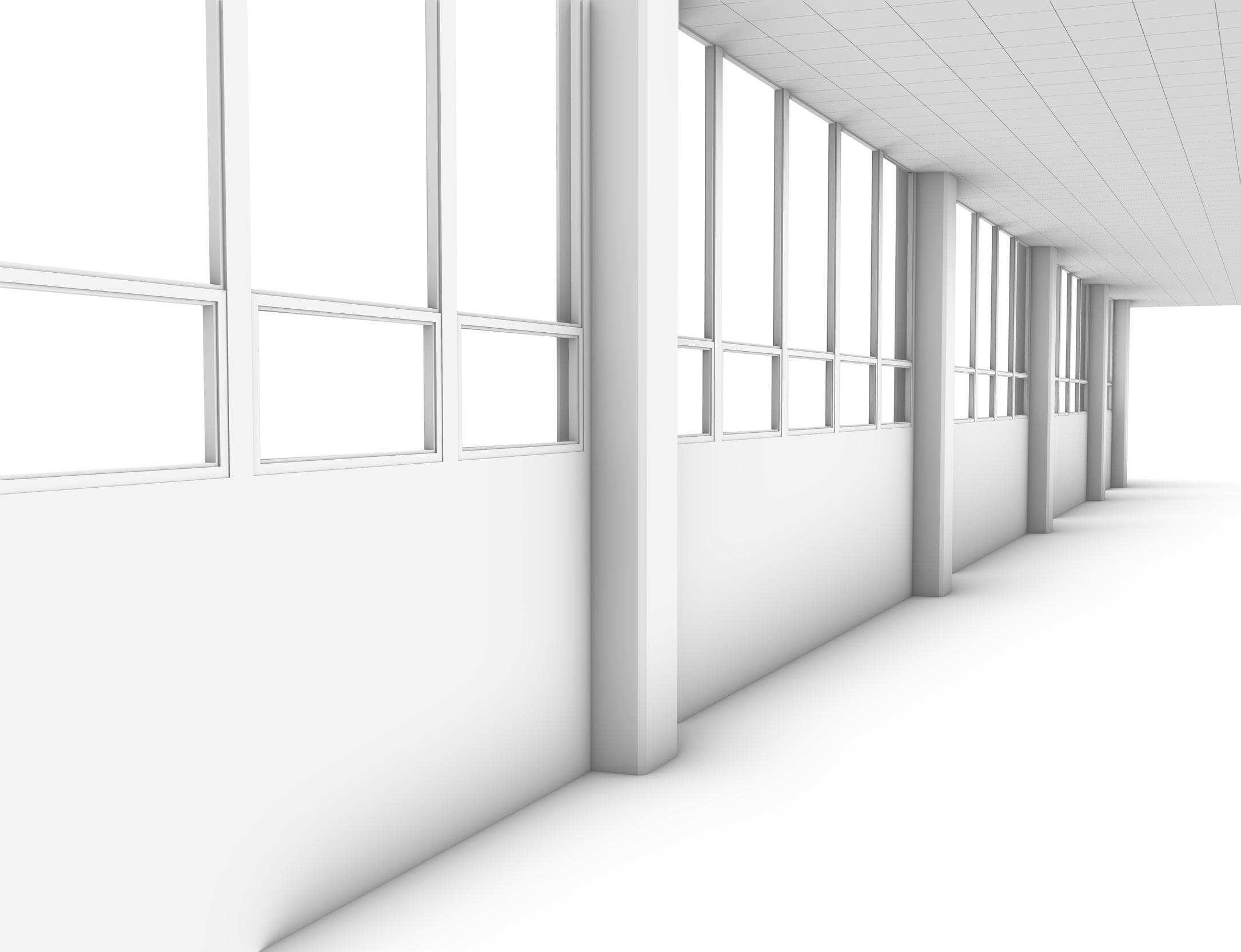
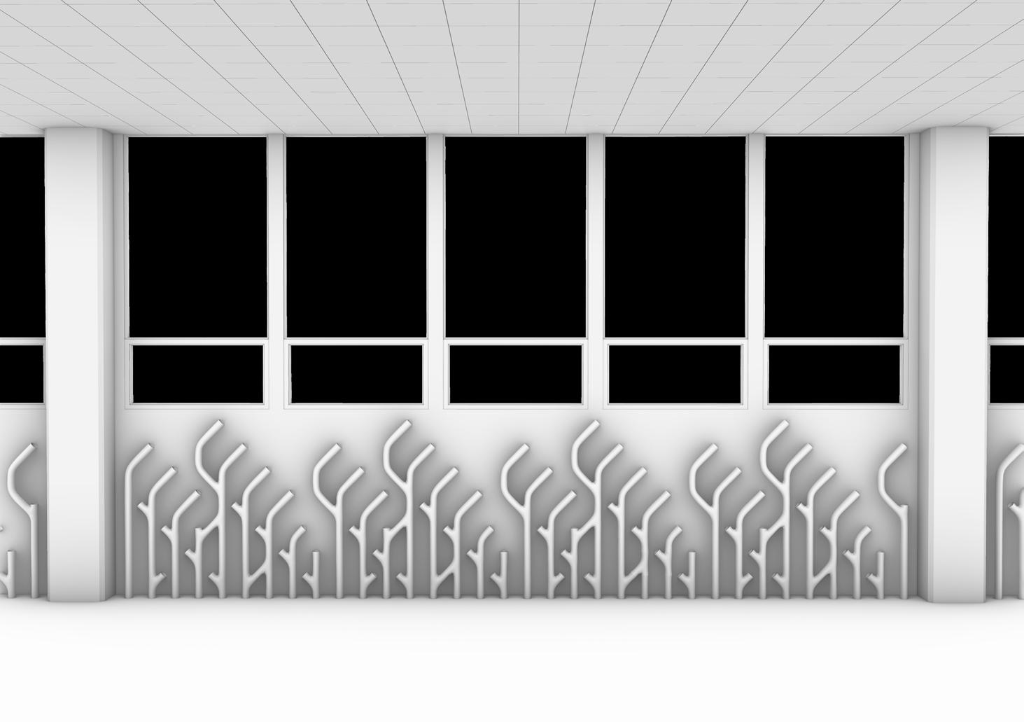
The initial installation design was developed by extruding the 2D pattern into a complex of 3D pipes. Plants are intended to be planted in the top of each of these pipes. This creates a density of plants which is higher closer to the correlating with measured light vales in the hallway.
Existing water and electrical systems were extended down onto the wall assembly. Water allows for plant growth and survival, while electricity supports a system of soil moisture sensors located by the root systems of each of the plants. These water and electrical systems are implemented together in this wall assembly to create an automated drip irrigation system, intended to support optimal growth and conserve water. Additionally, the water and electrical systems contribute to the aesthetic of the design of the installation, contrasting the organic shapes of the pipes and the plants.
This design removes the dropped ceiling and incorporates an exposed ceiling plane, which allows the installation to enclose and shape the space of the hallway,
IMAGES:
Installation with Plants
Installation with Plants Not Shown

COMPUTER MODELING
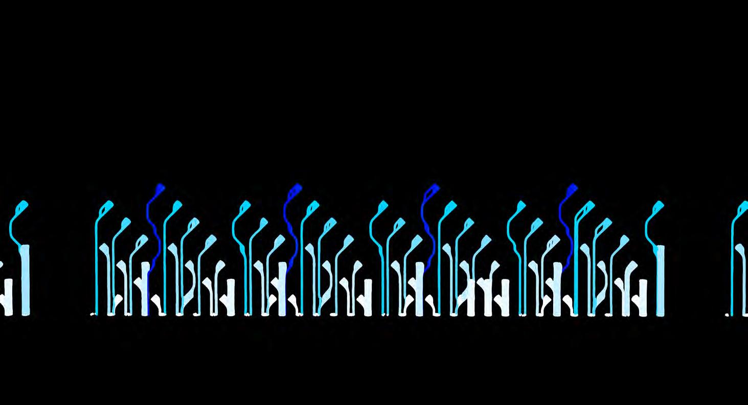
While a sensor system is design to provide only as much water as needed, any excess will be collected by a drain system located under the installation and between the columns.
IMAGES:
Installation with Computer-Simulated Water Flow
REFRACTION COMPUTER MODELING
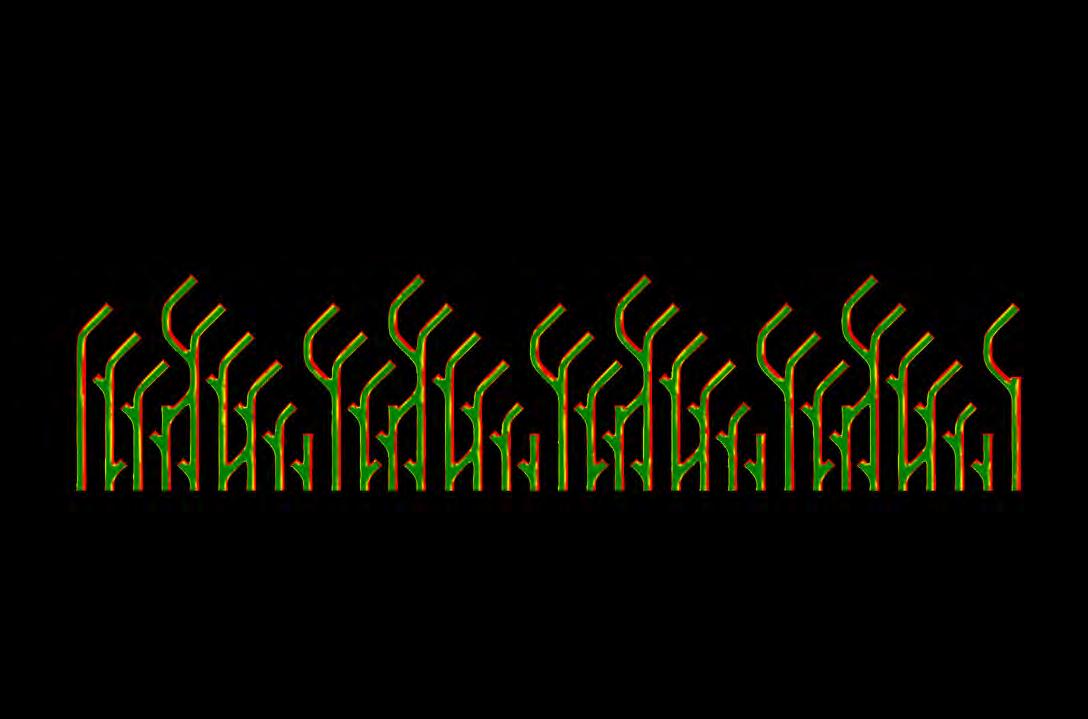
Computer modeling of beams of light and their paths of refraction was used to analyze yearly solar exposure on the installation design. This modeling revealed that the indirect light in this hallway is distributed evenly across the wall assembly.
This modeling informed the choice of plants for this installation, which remains consistent across the wall. A large variation in solar exposure would suggest the use of species with different light requirements in different locations.
JANUARY-DECEMBER, 5:00AM - 7:00PM

IMAGES:
Refracted Solar Exposure on Installation Pipes Detail
Refracted Solar Exposure on Entire Installation

DIRECT LIGHT COMPUTER MODELING
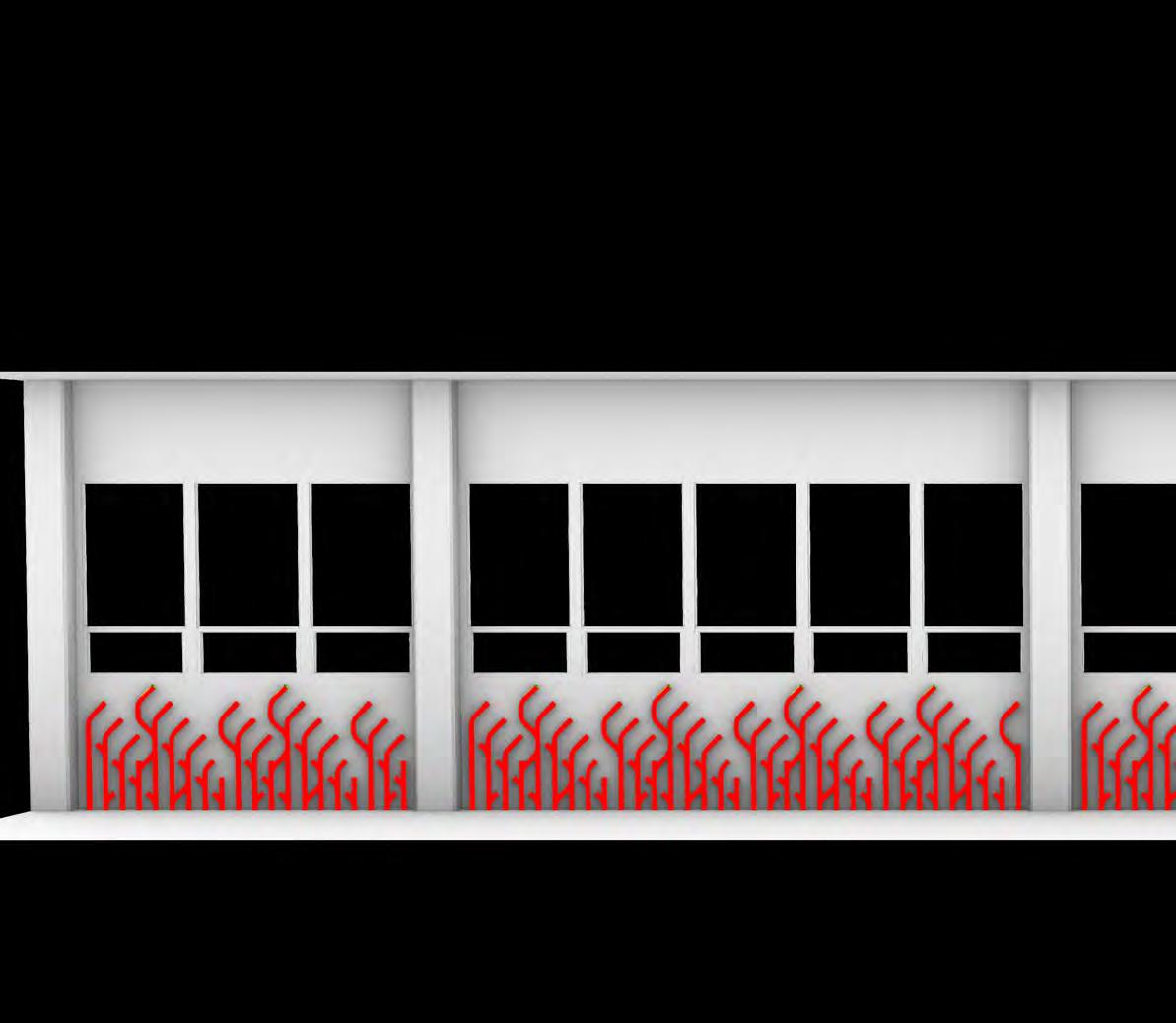
Computer modeling was used to analyze direct solar exposure on the installation. This modeling revealed that there is very little (almost no) direct sunlight that hits the wall underneath the windows. The only locations with direct sunlight are the very tops of the tallest pipes making up the installation.
This lack of direct light reinforced the choice of a low-light plant species for this installation.
COMPUTER GENERATED
JANUARY-DECEMBER, 6:00AM - 5:00PM

IMAGES:
Direct Solar Exposure on Installation Pipes Details
Direct Solar Exposure on Entire Installation

DATA VISUALIZATION
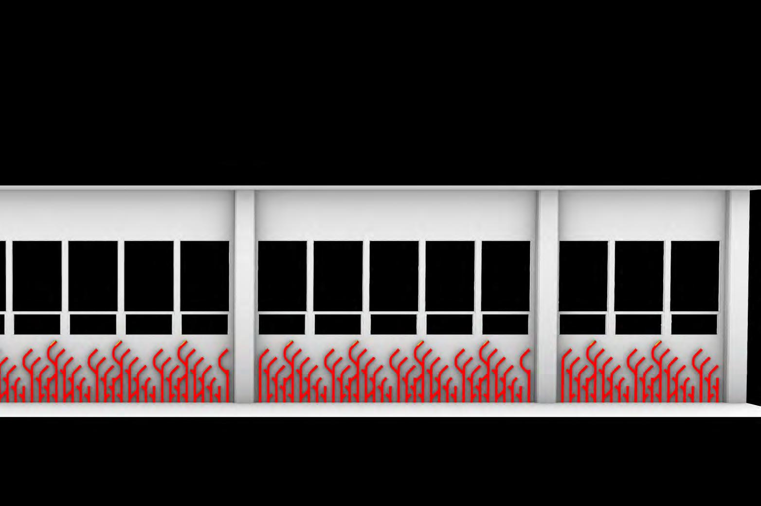
Data on existing light levels in the space were collected on a weekly basis around 3:00 pm during the month of February. These data show light levels (measured in lux) that are higher closer to the windows and lower closer to the ground.
This data informed the location of more openings for plants towards the top of the installation, where the plants will be in areas with higher light levels. These higher light levels are desired for plant growth in the overall low-medium light of this hallway. This is especially applicable under the windows, where only indirect,
AVERAGE EXISTING LIGHT LEVELS
FROM WEEKLY LUX MEASUREMENTS
FEBRUARY, 2023, ~3:00PM
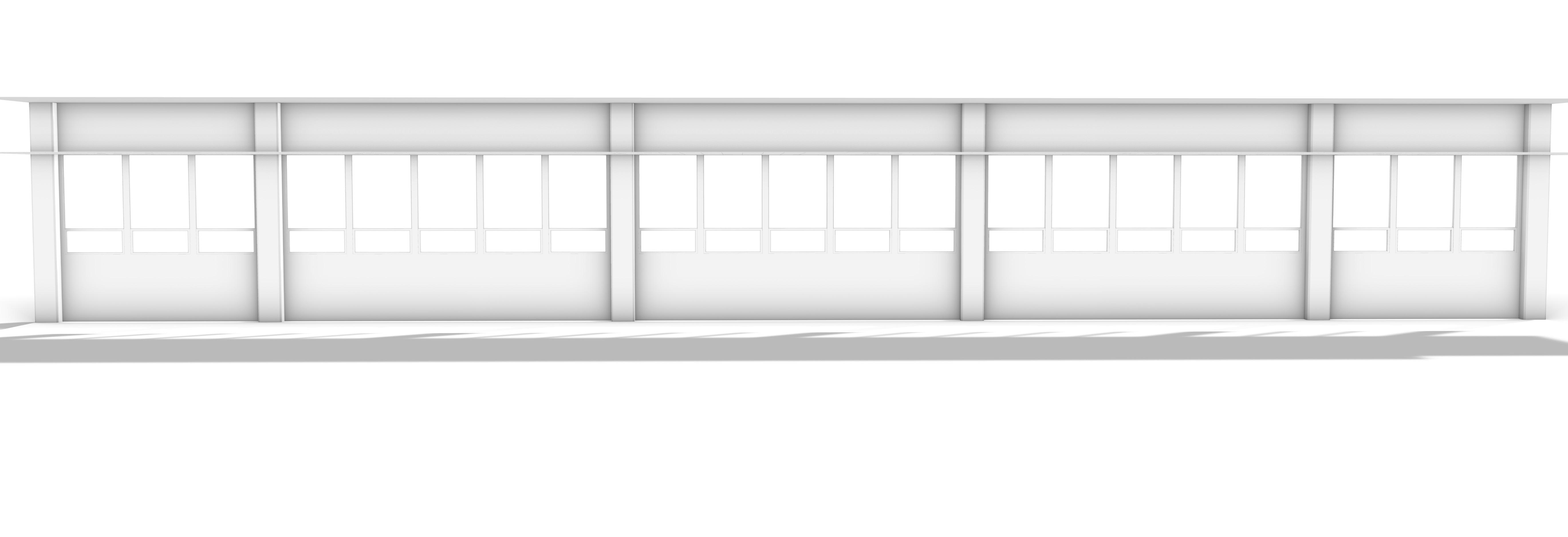
Visualization of Average Existing Light Levels

BIOLOGICAL SYSTEM INTEGRATION
“POTHOS”
EPIPREMNUM AUREUM
Light Type: Indirect
Minimum Light: 50 - 750 lux
Optimal Light: 2,000+ lux
Temperature Range: 70 - 90 oF
Pothos and Heartleaf Philodendron were selected for this installation because of their suitability for locations with indirect lighting. These species are very commonly used in indoor plant installations and kept as house plants.
While these species have relatively low light requirements, sunlight modeling and measurements of existing lighting levels in the space suggest that additional lighting is needed for the plants in this installation to thrive. Additionally, because these are tropical species, heating will likely be needed to maintain temperatures within the plants’ comfortable range. A preexisting hookup to the University of Oregon’s steam system provides an opportunity to integrate heating into this installation, maintaining the existing wall’s function as a heating and insulating element.

IMAGE:
Heartleaf Philodendron (left) and Pothos (right)

“HEARTLEAF PHILODENDRON” PHILODENDRON HEDERACEUM
Light Type: Indirect
Minimum Light: 200 lux
Optimal Light: 2,100+ lux
Temperature Range: 65 - 70 oF
IMAGE:
Successful Indoor Living Systems have Horticultural Lighting
Both computer sunlight modeling and measurements of lux values taken at the location of the installation indicate that the existing light levels would be too low to support the growth of Pothos and Philodendron plants. Therefore, horticultural lighting is needed to support the growth of these plants.
Calculations for the plants’ light needs looked at two important values: PPFD and DLI. These values are measurements of the amount of usable light received by the plants over a set period of time.
Calculations (found on the following pages) compare the optimal PPFD and DLI values for the growth of Pothos and Philodendron plants with the PPFD and DLI values that result from the preexisting lighting conditions in the hallway of study. These calculations determine the amount of additional horticultural lighting that is needed to support optimal growing conditions for Pothos and Philodendron.
PPFD = Photosynthetic Photon Flux Density
“Light as it is perceived by plants is referred to as photosynthetically active radiation (PAR). The amount of light reaching a surface, e.g. the plant’s leaves, is measured in PPFD, which stands for photosynthetic photon flux density. PPFD measures all photons (light particles) within the PAR spectrum in micromoles per
This means that PPFD specifically measures the light available to plants for photosynthesis and thus, impacts their growth.” *
DLI = Daily Light Integral
“The daily light integral (DLI) specifies the usable light received within a 24 hour window. The DLI combines light intensity (PPFD) with the lighting duration (photoperiod) over a 24 hour window and is measured in the unit of
* SOURCE:

IMAGE:
Average Lux Measurements in Lawrence Hallway
AVERAGE LUX MEASUREMENTS
LAWRENCE HALLWAY
FEBRUARY, 2023, ~3:00PM
NOTE:
Measurements taken at the floor level were not included in the average lux calculated for the space, as plants will not be growing at this level.

OVERALL AVERAGE LUX FROM LAWRENCE HALLWAY MEASUREMENTS (NEGLECTING FLOOR-LEVEL VALUES) : 531.5 LUX
SPECIES LIGHT NEEDS CALCULATIONS
LIGHT REQUIREMENTS FOR POTHOS AND PHILODENDRON:
Pothos (Epipremnum)
Philodendron (Philodendron)
EXISTING LUX TO PPFD AND DLI:
1. Average Daily Lux
According to measurements taken around 3pm weekly, during the month of February, the average daily lux value in the location of study is 531.5 lux .
(See previous page for the origins of this value.)
2. PPFD 531.5 lux =
(This is the PPFD value.)
(This is the DLI value)
NOTE: Use 12 hours of daylight in a day in Eugene, Oregon.
COMPARE VALUES FROM EXISTING CONDITIONS TO REQUIRED VALUES: 4. Average Required Values for Pothos and Philodendron
CALCULATE VALUES REQUIRED TO MEET BOTH PPFD AND DLI TARGET VALUES:
5. Compare with Existing Value and Determine Required Adjustment < 60
An additional
An additional is needed to reach the target values.
6. Convert Adjustment PPFD to DLI
Assuming the horticultural lighting will run for 12 hours per day, we can convert the minimum PPFD adjustment value calculated above (48.3 into DLI to see if an increase to the PPFD (lux) needs to be made to reach the target DLI value as well.
7. Adjust DLI and PPFD to Meet Target Values
4.25 is a factor we can multiply the PPFD value by to meet our target DLI
= 205.275
An additional 8,925 lux will allow us to meet both DLI and PPFD targets for Pothos and Philodendron.
For optimum plant growth, round this up to 10,000 lux grow lights.
CONCLUSION: Use 10,000 lux grow lights for 12 hours per day to meet Pothos and Philodendron light needs.
HORTICULTURAL LIGHTING AMBIENT LIGHTING
BIOLOGICAL SYSTEM INTEGRATION
Plantings in this installation will be located at the top opening of each branching pipe component. These openings are dispersed throughout the vertical plane of the installation, allowing for an even distribution of plants across the lower wall.
As the plants grow, their roots will extend plants selected for this installation are anticipated to also extend their leaves and vines downwards as they grow.
Horticultural lighting to support plant growth will alternate with ambient lighting along the length of this hallway.
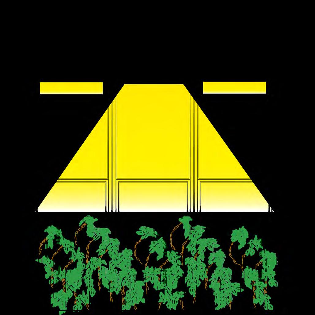
IMAGE: Plant Growth Diagram

GROWTH OVER TIME
INSTALLATION PIPE MODELING
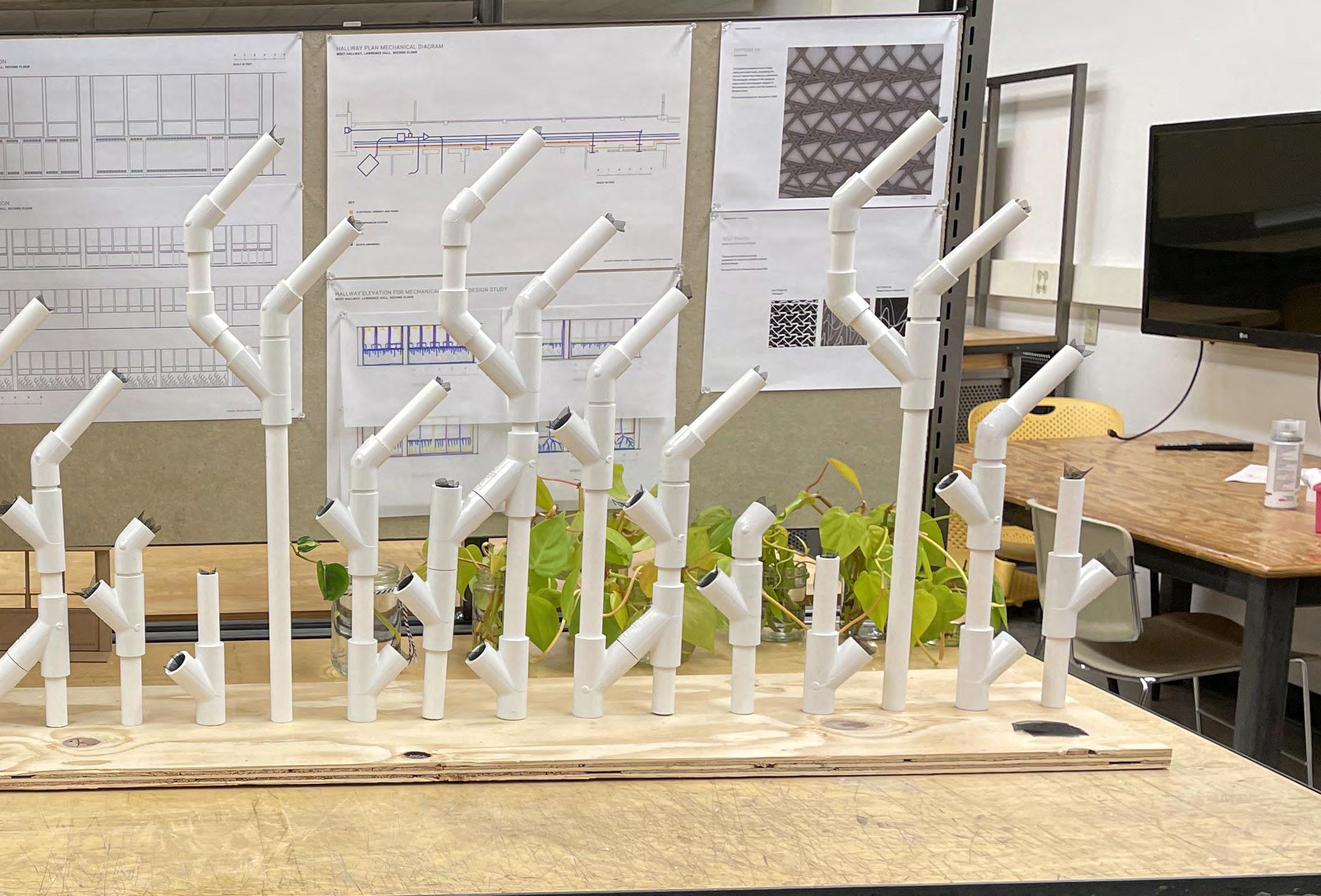
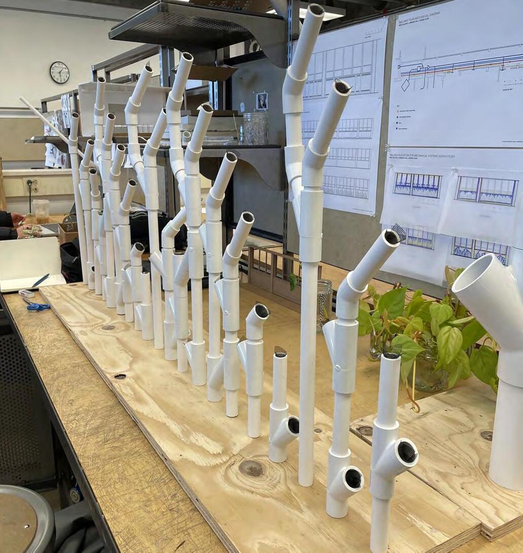
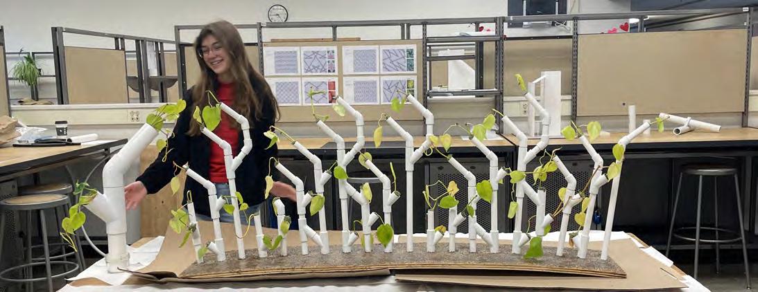
fairly well-established, large-scale physical prototypes were developed. A half-scale prototype was built of one small bay of the model in order to show the entire modular design. A full scale mock-up of a small piece of the overall installation was also built. These models were used to test the structural stability of the installation.
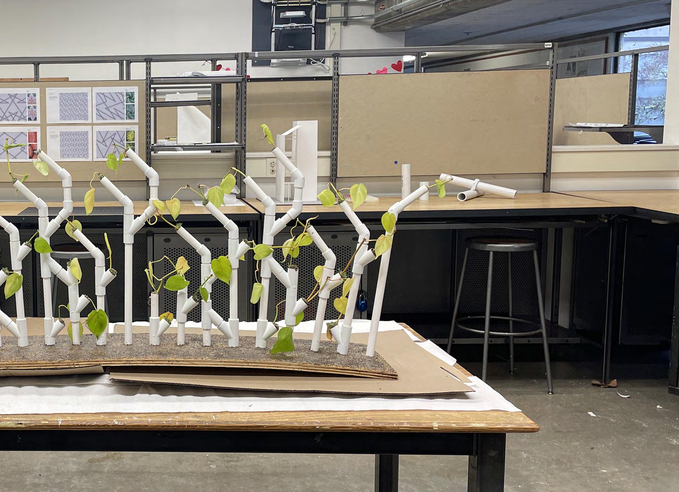
These physical prototypes were built out of standardized PVC pipe connectors and pipes. These off-the-shelf components were strategically selected to prove that the design concept could be viably built with easily-accessible materials.
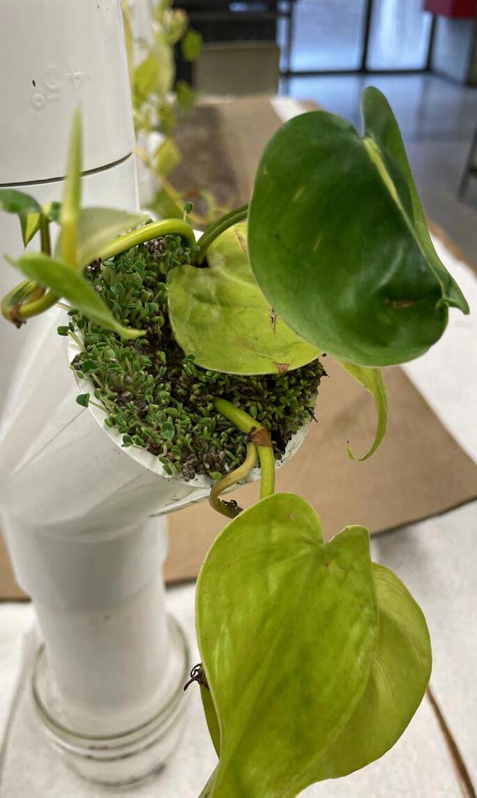
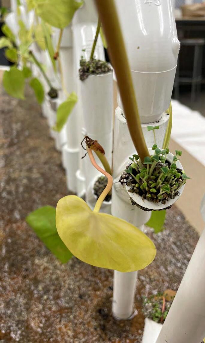
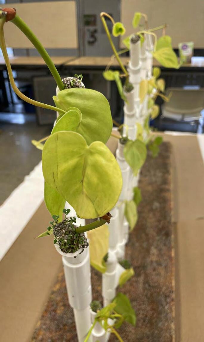
Once built, these prototypes were planted with both a selected plant species, Pothos, and Chia. These plantings tested the ability of the design to support plant life. This experiment also allowed for the analysis of the interaction between plant growth and the design.

IMAGES:
Full Scale (Left) and Half-Scale Physical Prototypes
IMAGES:
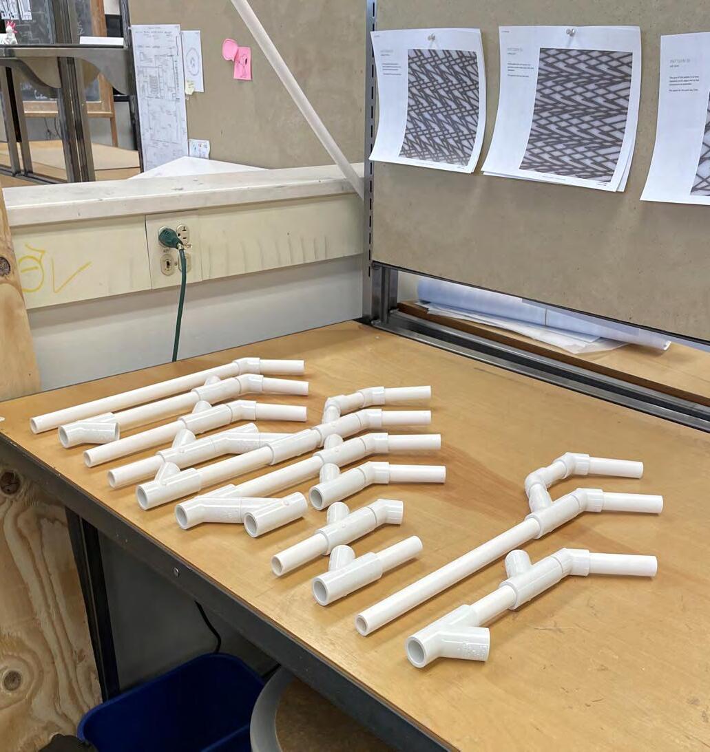
Half-Scale Prototype Before Planting (Below) Pipe System Construction (Right)
INSTALLATION PIPE MODELING
Prototypes were built by measuring and cutting PVC pipe pieces and attaching them using 45 degree angle and 45
piece of plywood using wooden dowels.
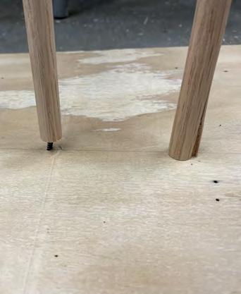
Attaching the dowels to the plywood resulted in some split dowels and some screws that didn’t go all the way into the dowels. Some of the dowels had to be reattached multiple times before they
Once the models were constructed, mesh was placed in the openings. When the models were planted, this mesh prevented the soil and plants from falling too deep into the pipes.
IMAGES:
Split and Poorly-Screwed Dowel Connections Model Base Construction

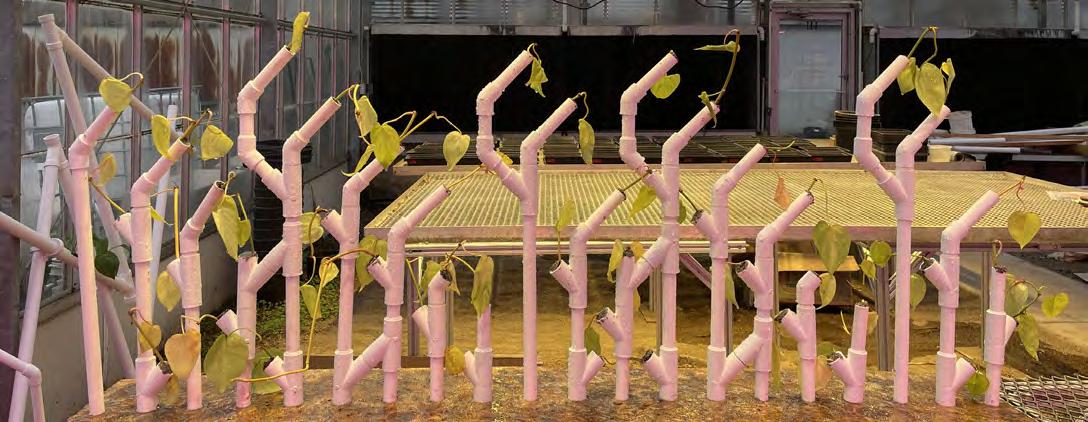
IMAGES: Prototype Growth in Greenhouse Environment
PROTOTYPE PLANT GROWTH
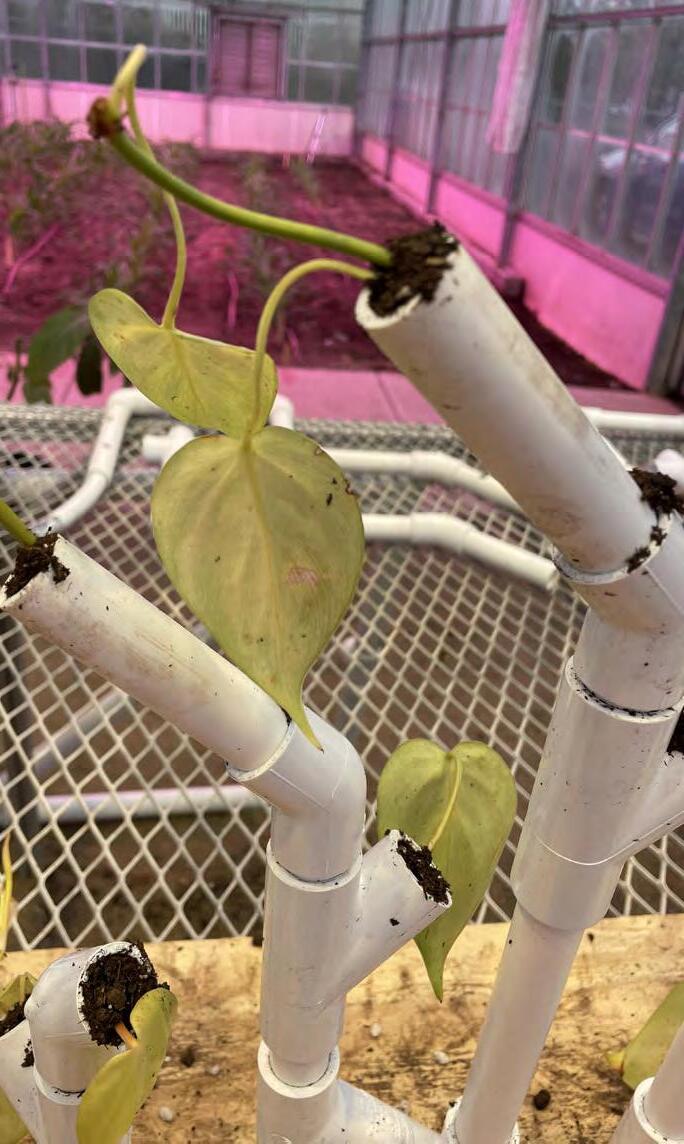
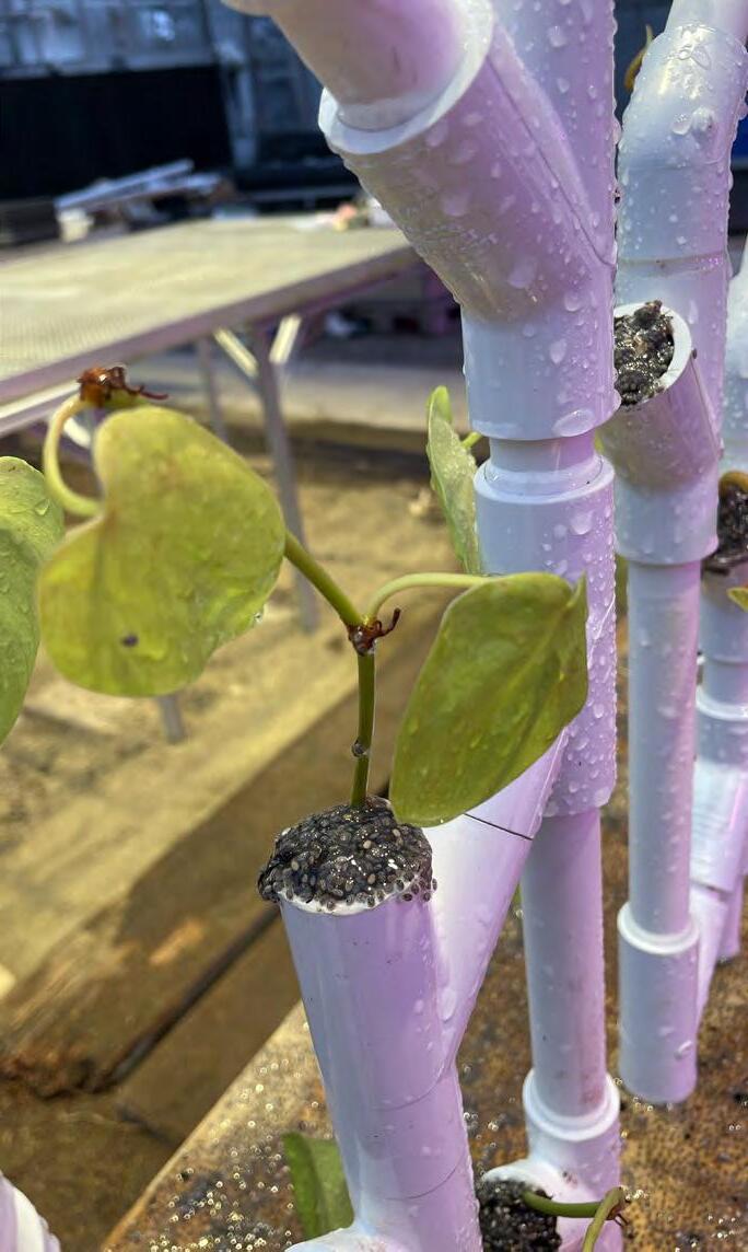
Finished prototypes were grown in a greenhouse for two weeks. The Pothos plants seemed to be struggling in the intense horticultural lighting of the greenhouse, so the prototypes were then moved back into a standard indoor environment for one week. At this time, the prototypes were also planted with Chia. The plants seemed to do much better in the normal indoor environment with more constant watering and oversight.
Overall, these prototypes successfully supported plant life. The plants remained alive. However, intensive maintenance was required to keep the soil moist in the half-scale prototype. The smaller diameter pipes of this prototype are likely too narrow to support plant life in the long term.
An interesting development from physical prototyping was that the plywood baseboard warped over time due to watering, adding a slightly arched shaped to the half-scale prototype.

IMAGES:
Continued Prototype Growth in Studio Environment
IMAGES: Digital vs. Physical Comparison
DIGITAL VS. FABRICATED
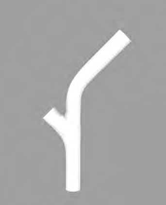
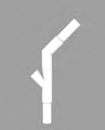
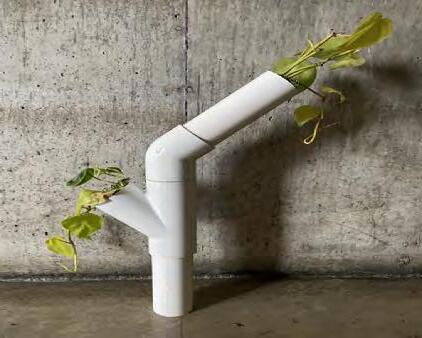
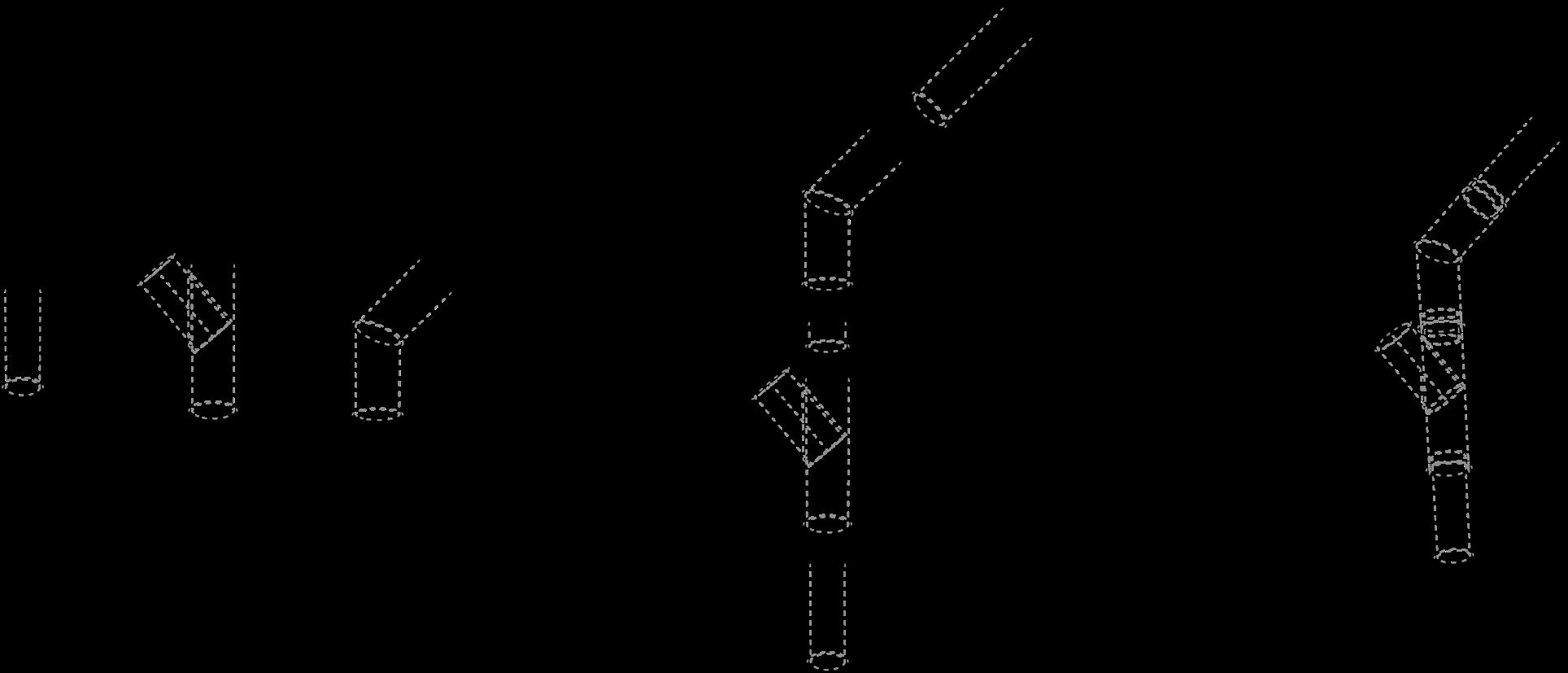
The physical fabrication of the digitallydesigned installation pipe structure required that the structure be broken down into modular components. The design process for the installation, which centered on repetitive polygonal forms and used modular digital components, ensured that the process of physical fabrication would be relatively simple. While the design appears complex, it could be fabricated out of only two joint components and varying lengths of straight PVC pipe. The planar nature of the design also facilitated ease of construction.
A major development in the design that resulted from the prototype fabrication process was a variation in pipe diameter. PVC joint components have a larger diameter than the PVC pipes which they are designed to connect. This resulted in a physical prototype that appeared much more visibly jointed than the smooth and


IMAGES:
Digital to Physical Design Development
Component Assembly Diagram
PROTOTYPE FABRICATION PROCESS
COMPONENTS
ASSEMBLED DESIGN
FINAL DESIGN
installation in the hallway of Lawrence Hall incorporates the geometric pipe system systems. The removal of the dropped ceiling from the space allows for the exposure of the mechanical systems. Bright colors evoke the Centre Pompidou, while helping occupants of the space understand how pieces connect and work together.
sprinkler, electrical, and steam heating
system is diverted to pump boxes above the window arrays. In these pump boxes,
injected. A computer, which connects to the integrated electrical system, directs this fertilized water to each individual planting site, where a water saturation sensor is located. The many water and electrical pipes that make up this system frame the window array and follow an aesthetically-engaging branching pattern.
The steam heating system has been redesigned from the existing condition
optimal growth for the tropical species used in the installation and maintains a comfortable temperature in the hallway for human occupants.

IMAGES:
Installation with Plants
Installation with Plants Not Shown

FINAL DESIGN
most clearly the interaction between the design of the pipe structure and the design of the branching water lines that serve each planting. While both systems are branching, the design of the installation pipe structure echoes the organic and irregular branching formations found in nature. In contrast, the water lines follow orthogonal and geometrically regular branching structures often found in man-made systems.
Water and electrical systems are maintained at the plane of the previous dropped-ceiling. This choice avoids any additional costs that would be incurred by the redesign and re-installation of these systems. Additionally, these systems provide the appearance of a partial dropped ceiling in the hallway, contributing to an engaging and layered ceiling plane.

Elevation Showing Plants, Installation Pipes, and Mechanical Systems

DESIGN
clearly shows a layering of elements along the wall plane. The existing wall plane and window array are maintained, while the previous bulky radiant steam heating system has been removed. This steam radiant heating has been redesigned as an heating units. The steam heating function was maintained to take advantage of the preexisting connection to the campus steam heating system in this location. The electrical lines to span from the wall to the planted pipe installation. These water and electrical lines will be covered in a remain unimpacted by the warm air that at the wall’s base. This air will insulate the wall assembly.
This pipe installation will function as a hydroponic system that runs fertilized growing medium. The insulative properties of rockwool and its suitability as a growing medium for plants suggests further explorations of rockwool-based wall assembly systems that both support plant life and provide insulation.

IMAGES:
Plan Showing Plants, Installation Pipes, and Mechanical Systems

FINAL DESIGN
Wall sections clearly show the layering of the installation and its supporting mechanical systems outward from the wall.
Electrical and water lines are run along the wall. A gap is left for the radiant-steamplane. The pipes of the installation and its plants are located furthest from the wall plane and closest to occupants of the space. A drainage system is located under plane. All of these elements are carefully placed within the gap between columns,
the old radiant heating system and not protruding into the main space of the hallway.
HVAC and data conduit remain in the ceiling plane, as does much of the electrical system, which has been ambient lighting.
ELECTRICAL SUPPLY
WATER SUPPLY
STRUCTURAL SUPPORT TIES BACK INTO WALL
WATER SENSOR AND DRIP IRRIGATION AT EACH PLANTING LOCATION
IMAGES:
Wall Section (Left)
Wall Section Detail (Right)
ROCKWOOL PLANTING MEDIA
WATER DRAINAGE
STEAM SUPPLY STEAM RETURN
FINAL DESIGN
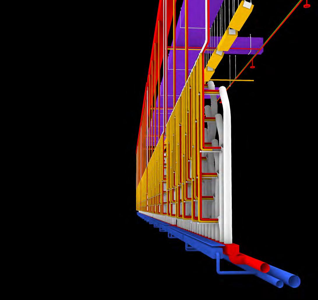
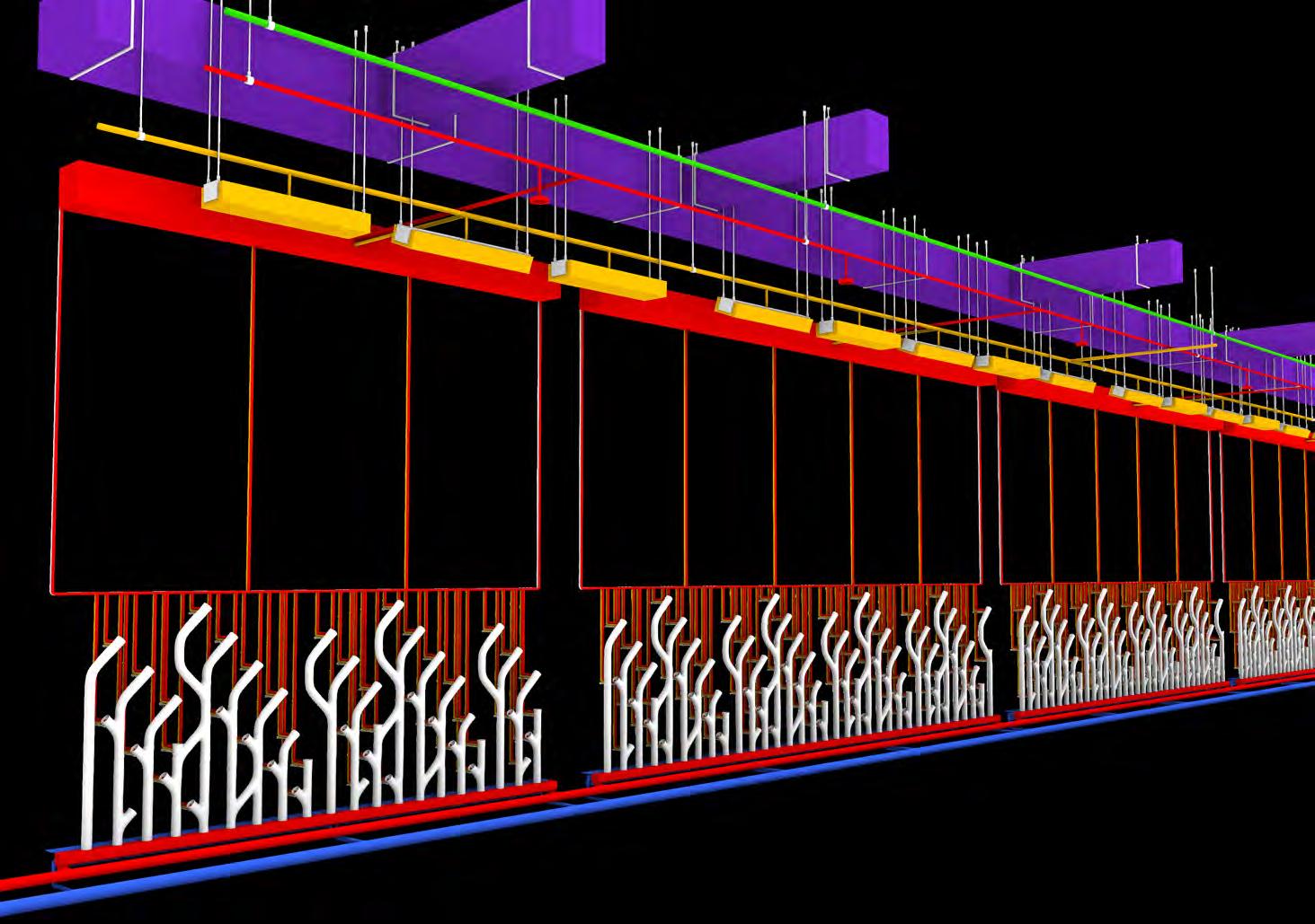
Mechanical systems in this design serve many purposes and are highlighted as a focal point. Electrical and heating systems maintain temperature and lighting levels
sprinkler system serves a similar dual function, providing safety for people and sustenance for plants. Additionally, these brightly painted systems contribute a playfulness and artistic character to the space. Their branching patters allude to the similarities and complexities of both man-made and living systems.
Mechanical systems in this design are not only beautiful, but also economical and streamlined. Wherever possible, existing systems were maintained. Systems are compactly located close to the wall installation, easy to access for maintenance, and clearly laid out.
IMAGES:
Layout of Mechanical Systems and Installation Pipes
FINAL DESIGN
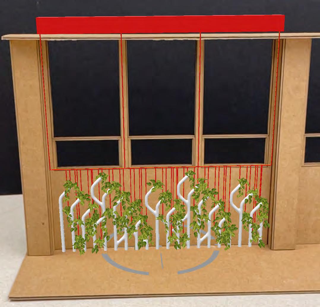
Experiments with virtual reality (“VR”) were used to visualize the designed installation in the existing space in Lawrence Hall, as well as in a physical scale model. These experiments used a digital model of the installation built in Rhino and a free VR software called Fologram.
Overall, Fologram proved to be an unreliable tool with relatively low accuracy. Models often failed to load properly, and linking the digital model to the mobile devices used to visualize the design in or reliably in physical space. Additionally, image outputs (seen here) were of low resolution and quality.
Further explorations in VR should explore other available software or pre-recorded VR visualizations.
IMAGES:
Scale Model with VR Installation (Left) Lawrence Hallway with VR Installation (Right)

IMAGES:
Installation Model with 3D Printed Supports
Installation Model in 3D Printer Software
FINAL DESIGN
was 3D printed in resin to create a result
This 3D printing process was undertaken to explore and learn a new fabrication technology.
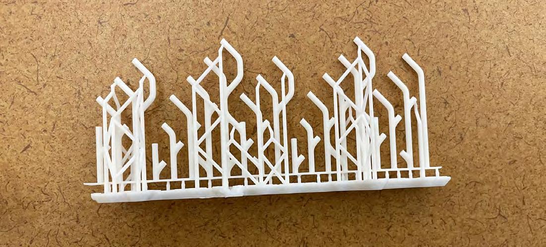

IMAGE:
Scale Model with 3D Printed Installation


FREESTANDING VERTICAL SYSTEM
The third phase of this project explored how the installation developed in the second phase could be systematically implemented in different architectural contexts. Three theoretical design ideas explore variations to the orientation and form of the original pipe installation and how mechanical and structural systems growth.
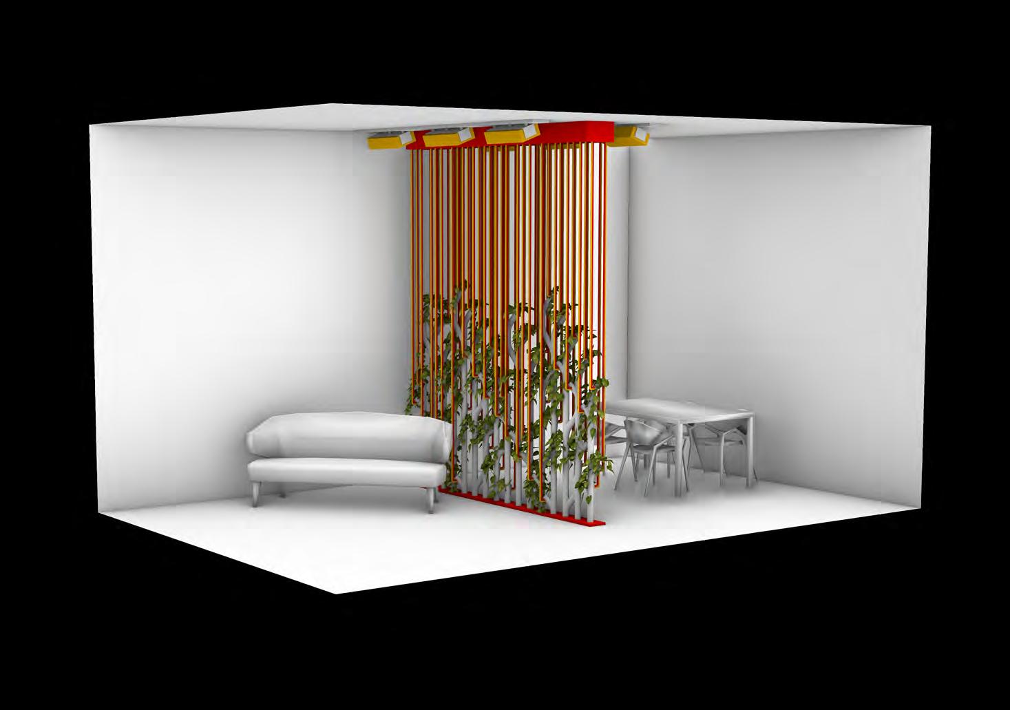
installation could become a freestanding wall. The idea of a partition wall takes advantage of the screen-like porous layers of the original design. A base and top piece become essential nodes for structural support and mechanical system integration.
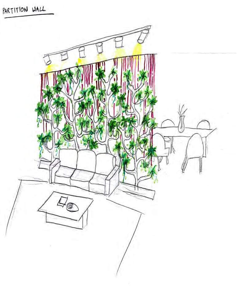
IMAGES:
Partition Wall Rendering (Right)
Partition Wall Concept Sketch (Left)
SUSPENDED HORIZONTAL SYSTEM
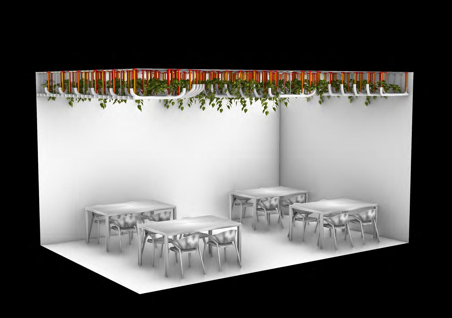
Application of the principles of the original wall installation as a ceiling assembly explored how changing the orientation from vertical to horizontal impacted the overall design. In this design, the network of pipes acts as a vessel, keeping the water, as well as the plants, inside. The incorporation of vining species like Pothos and Philodendron is key in this application, as these vining plants will drape down into the space, becoming more noticeable to occupants. In this system, lighting, structural supports, and water lines are all suspended from the ceiling plane.
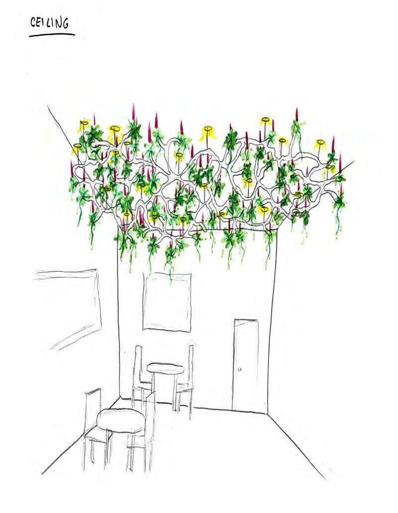
IMAGES:
Ceiling Assembly Rendering (Right)
Ceiling Assembly Concept Sketch (Left)
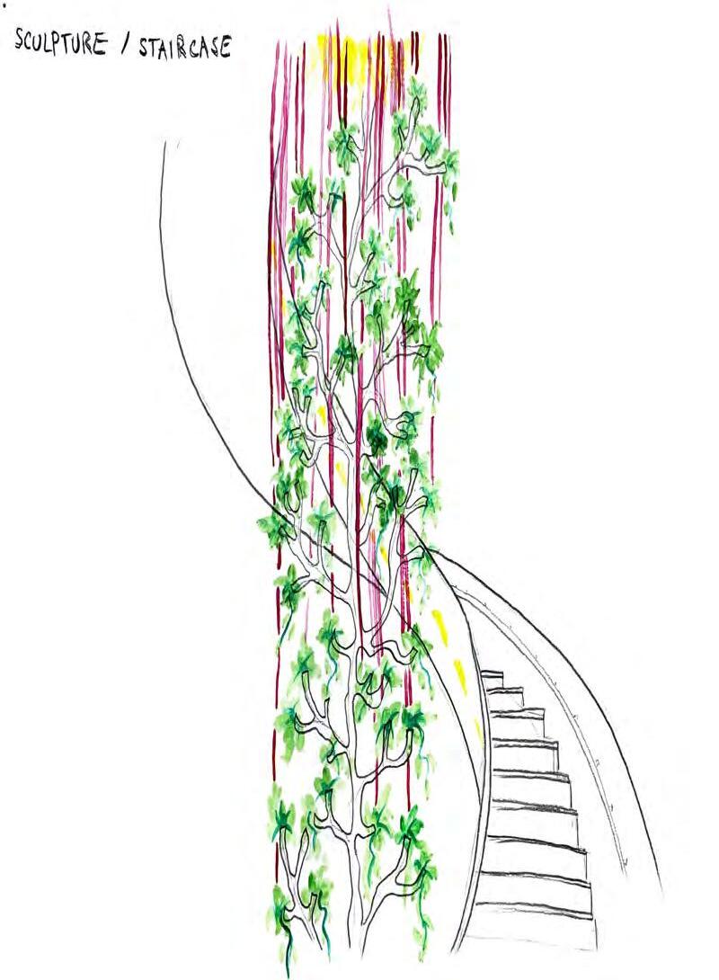
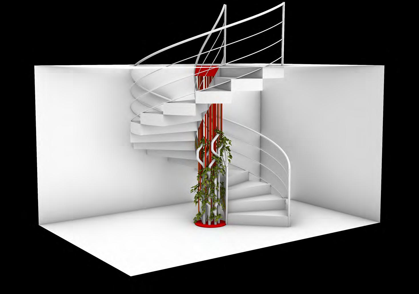
SCULPTURAL COLUMNAR SYSTEM
An exploration of a staircase centerpiece installation explores how the pipe system could become columnar and sculptural. In this application, water pipes double as structural supports, and lighting is integrated not within the installation itself, but in the surrounding staircase. The result of this exploration is a chandelierlike object that is a focal point in the space.
IMAGES:
Staircase Centerpiece Rendering (Right)
Staircase Centerpiece Concept Sketch (Left)


This project allowed for an in-depth exploration of mechanical systems design and integration, as well as various fabrication methods. Experimentation at many scales facilitated the testing of the ability of a design to support indoor plant life.
A major goal for this project was to design an installation that is not only beautiful, but also functional when integrated into its intended location. All design choices in this project were made with the goal of viability in mind, and it is believed that
resulting installation design could be successfully integrated into Lawrence Hall.
Currently, the integration of living systems into the indoor built environment takes very limited forms. Potted plants and planted “green walls” remain the most common options. This project suggests that plants could be more systematically integrated into the essential mechanical systems of a building. An acknowledgment of the many mechanical systems required to support indoor plant life suggests that this may also be the the indoor environment at a large scale.

