










2 Module 2 Module 1
Vase, Infill, Gradient
Tolerance Test, Modular Assemblies







Vase, Infill, & Gradient



VASE DESIGN
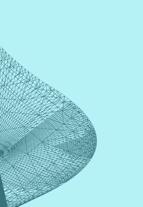
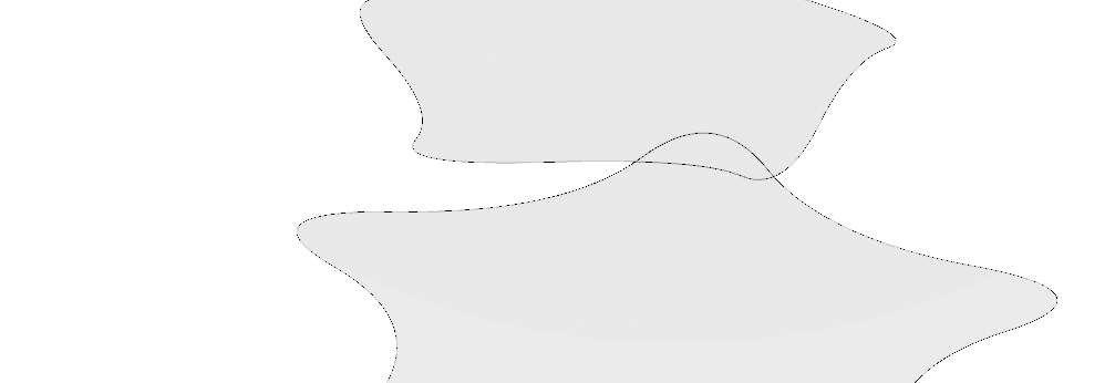
As an introduction to 3D printing, the first model created was a dynamic object that could act as a empty, free standing object with no internal structure.
Due to time constraints, documentation of the printing process was not captured.


Tips
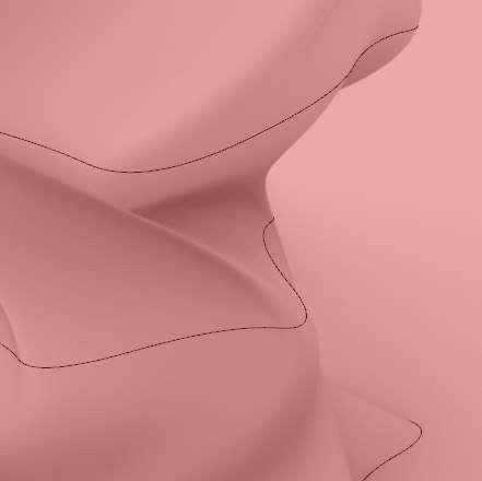
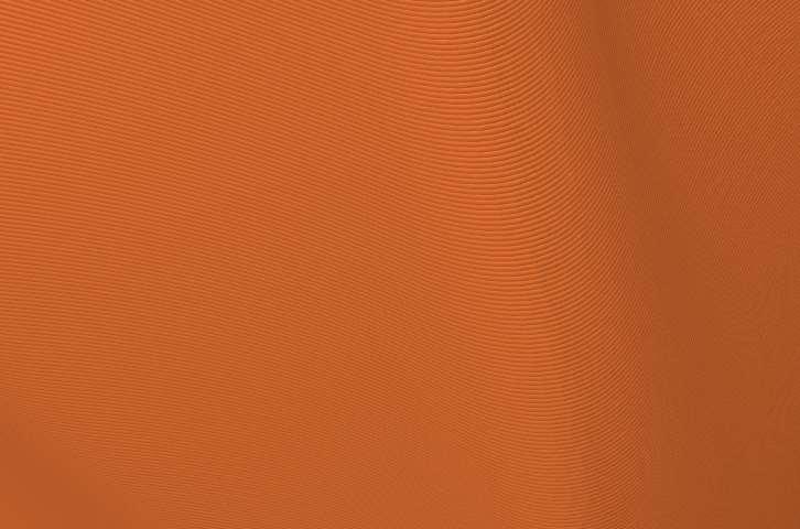
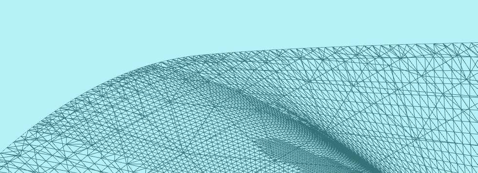
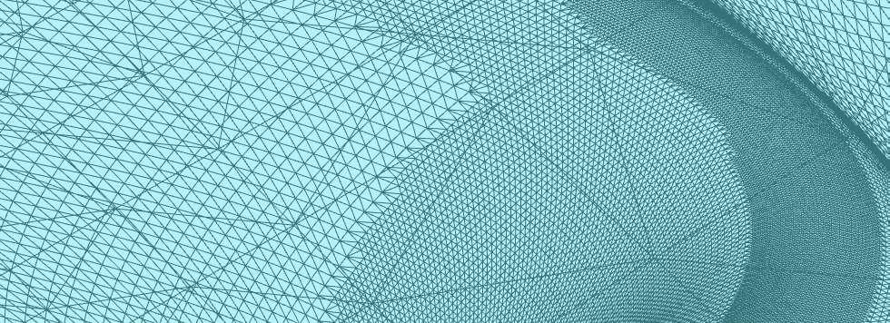
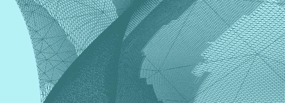
This model shows an example of something to look out for before sending a model to print. Try to avoid tight points on the model from lvaping on top of one another
Before printing, look over the 3D model to ensure that there are no gaps in the model. Lines should have a slight overlap on top of one another. This will ensure a solid
print. For examples of what it looks like when lines do not overlap, please go to the Chapter 3, Infill Without Walls.
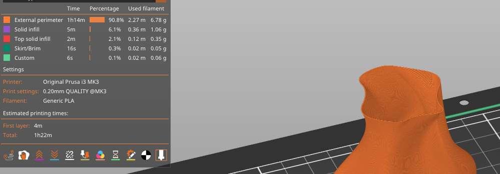
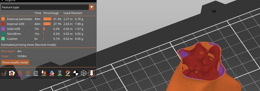
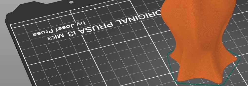
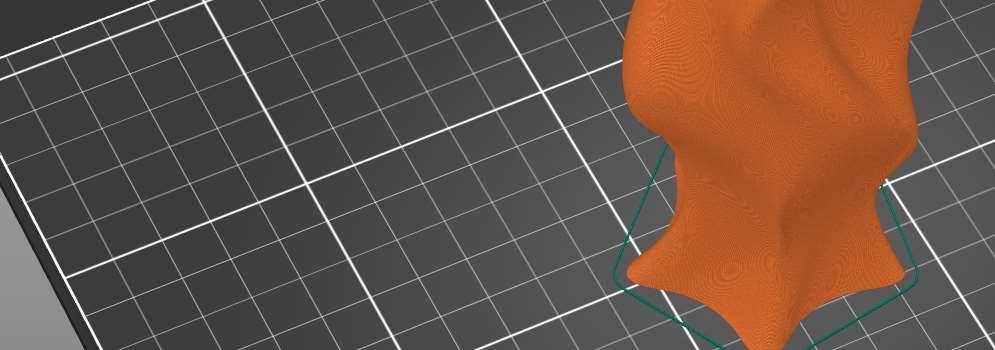
No Infill versus Infill Models
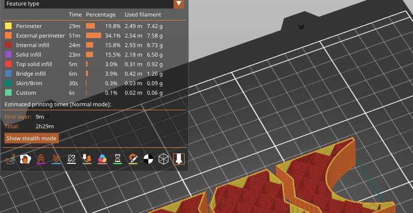
This image shows the model within the Prusa cutting software. Despite the model having no infill, it would require the printer around a hour and a half. As a frame of reference for time, at a 5% infill added to the inside of the vase, it would increase the weight time another half an hour.
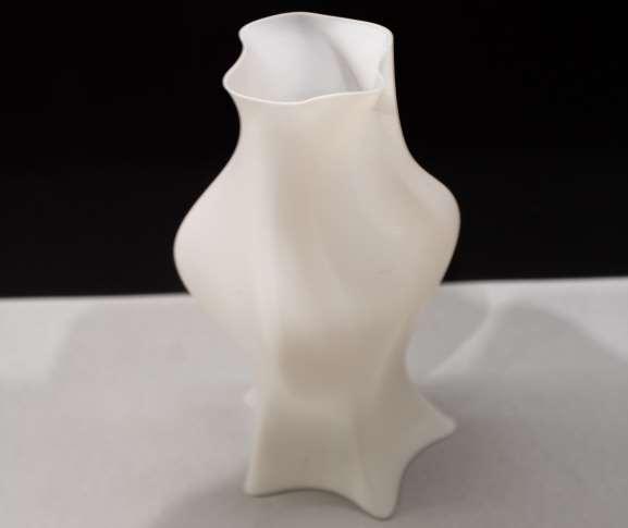
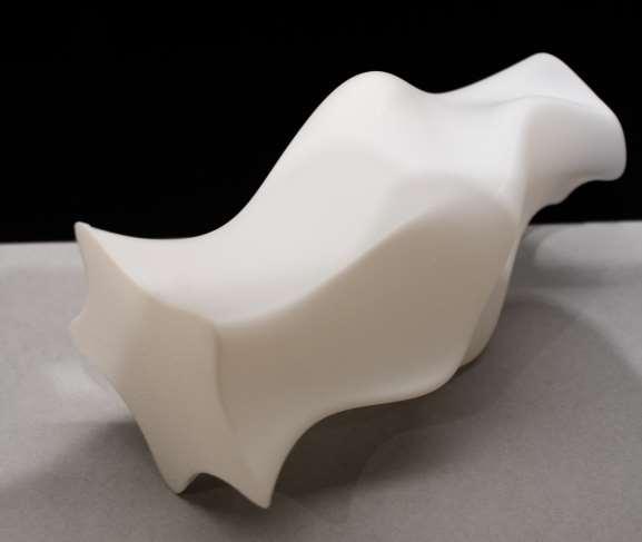
Finished Models
Takeaways: Close attention needs to be made not only during the 3D print process, but the modeling aspect as well. Ensuring that there are no gaps in the model will increase the likelihood of the print having no errors.
Note: As new machines are made, their modeling capabilities increase. This model was printed using the Bambu, rather than the Prusa. This affects the smoothness of the model itself, as you will notice in the printed model going onwards looking a slightly rougher.
Infill Design
Infill acts as a structural support system inside the 3D Printed Models. This is important to know as tall models might collapse during the printing process. Adding an infill will prevent any collapse and will help create a stronger model.


When 3D printing an object with a small base, add a Raft Layer to the model. This can be found in the print settings under “Support Material”. This will help the stand up right during the printing process. It is recommended to use 2-3 layers.
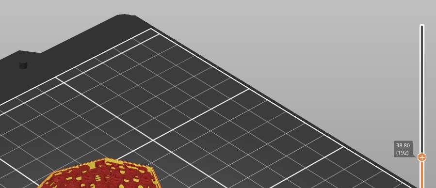
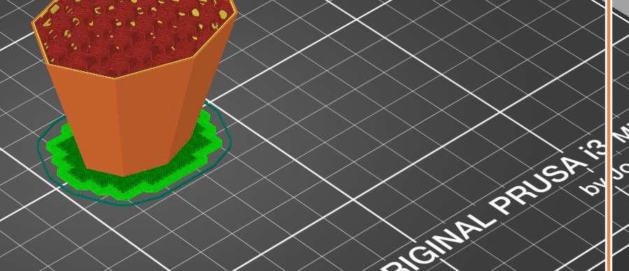
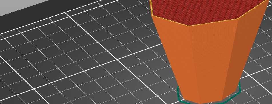
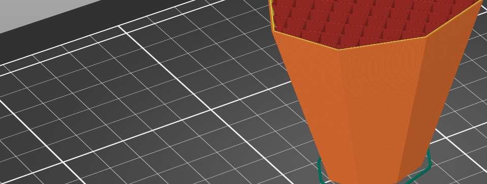
This slider bar in the preview section will allow you to see a section cut of your model. This lets you see the layering and how the infill layers will work in your model
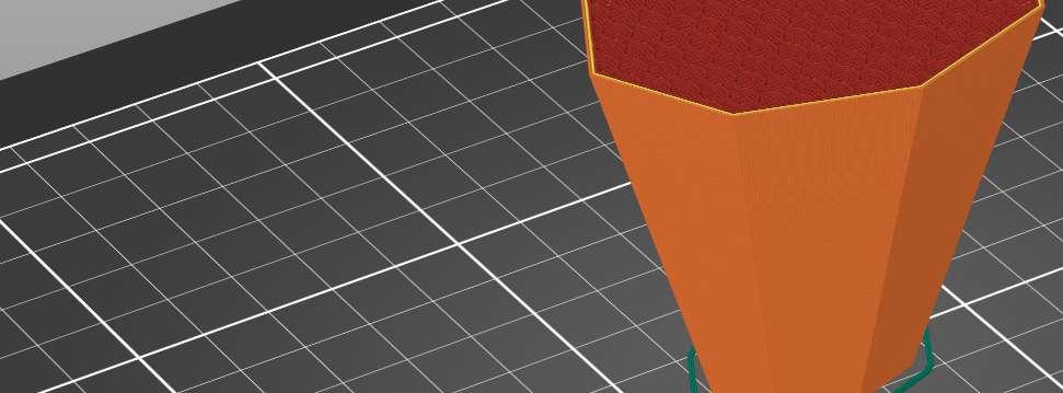
Using Different Infill Types
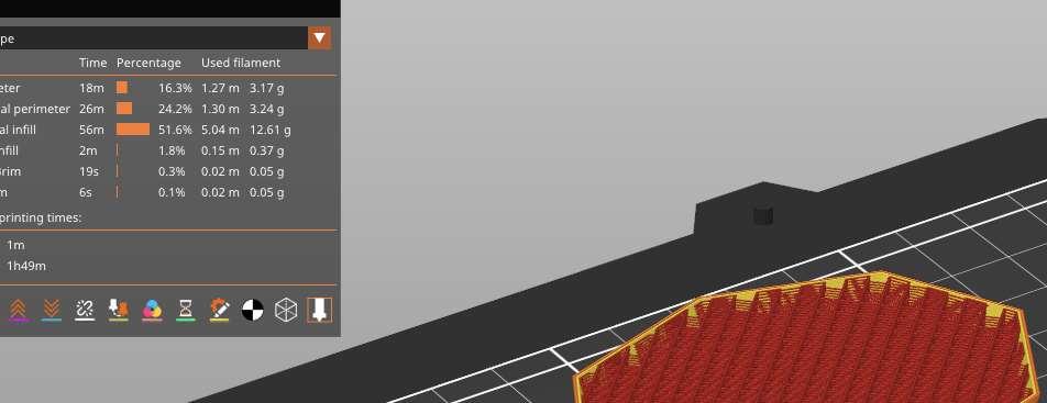
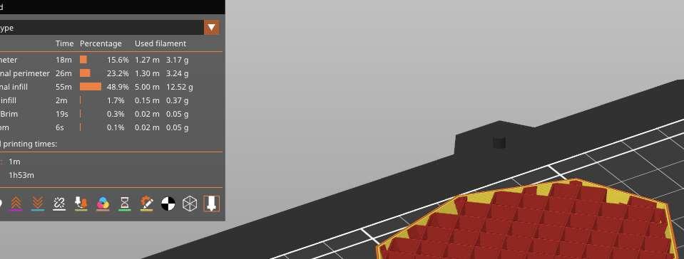
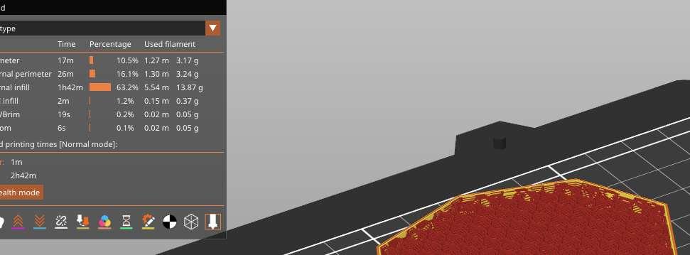
Unless the model is exposing the interior of the model to show infill, it is important to choose the right option for your model. The examples show how the printing time varies between the different infill types despite having the same infill amount. If using a community 3D Printer, take time to consider the type of infill pattern needed to suppport the model.
Using the same model at a different 15% infills, the times were as followed:
Rectilinear - 1 Hour, 49 Minutes
Grid - 1 Hour, 53 Minutes
3D Honeycomb - 2 Hour, 42 Minutes
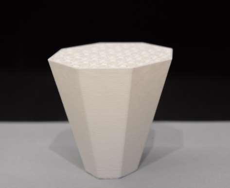
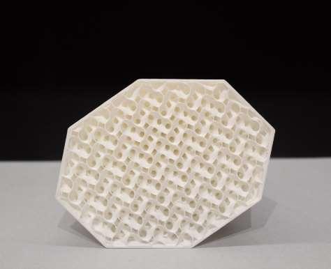
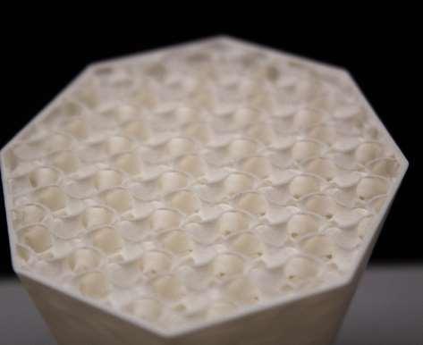
Finished Models
Takeaways: The 3D process seemed to be a smooth process while printing the model. Small strands of PLA did occur around the model itself, but had no significant impact on the structure. The model was printed on a 3 layered raft and was taken off after the model was completed.
Note: Compared to the vase model, printed on the Bambu, versus the infill model, printed on the Prucia, there is a difference in texture. This was noted on the previous chapter, but is more evident to see on the infill model images
1_ Printed Model, Side View
2_ Printed Model, Top View
3_ Printed Model, Infill Close up
This print was to show the intricity of an infill for the 3D printer. This model can show how the infill connects the shells together and provide a stronger structure. The process of making this model was creating a solid object in Rhino, then remove the vertical and horizontal shells using the Prusa App.


Tips:
Although the speed is faster, you can see how much more structure adding another 5% infill can have on the model



Potential Issues
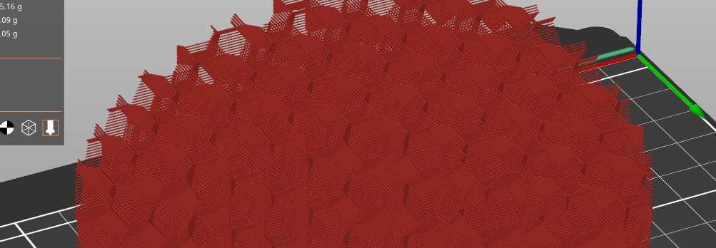
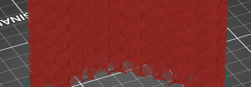
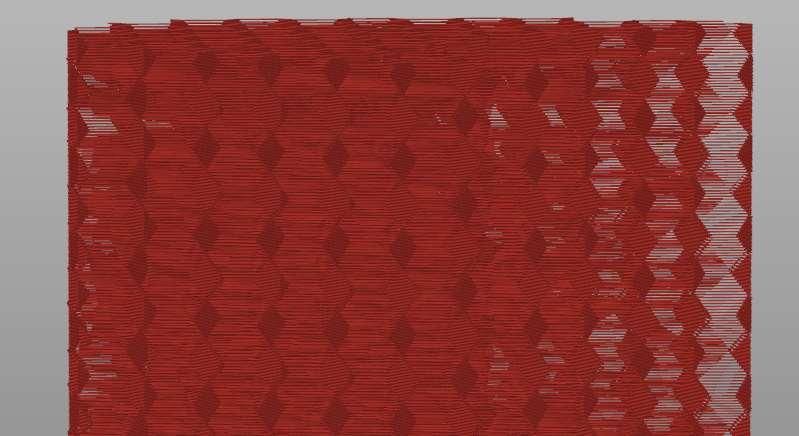
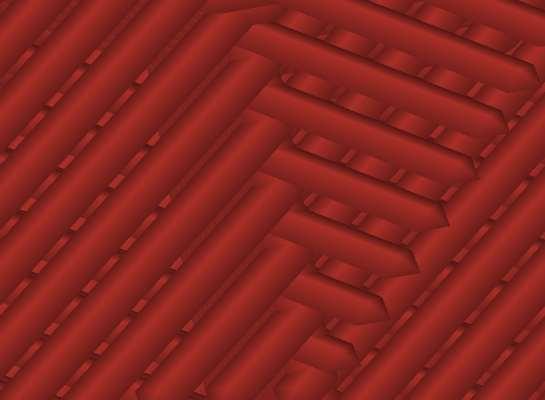
The 3d Honeycomb infill shows a good example of what to look out for before you 3D print models. Notice looking at the side view of the model, there spaces where you can the gray background. This would mean the PLA layers would not be place ontop of one another, cause a collapse in the model. Do not assume that the 3D printer will correct itself as a smart program
while printing. The 3D printer will only follow the colored lines. Looking at the last image, the lines do not over lap but alternate in which direction the go. This would work as a infill, but it serves as a learning lesson on what to look out for in the shell of models
2_
Finished Models
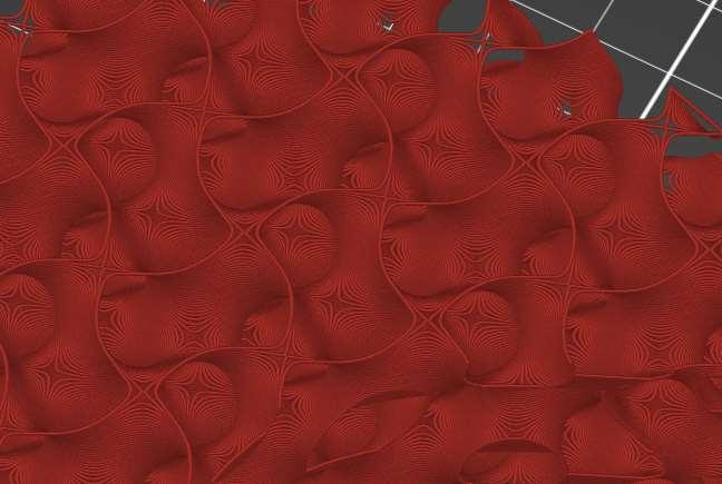
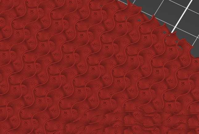
Takeaways: I had printed two model, both gyroid infill but one at 5% and another at 10%. I did this as I noticed gaps appearing on the model in Prusa. While both models are sturdy, the 10% was much cleaner during the print as well as stronger.
The 5% infill model seems to show stringing and missing filaments in certain areas. This is most likely due to not having a strong connections to other parts of the model. In the model before printing, you can see how lines do not overlap over one another.


Although the 10% seems to show similar issues, the distance of the non-overlapping parts are a shorter distance.
1_ Prusa Model, Gyroid 5%, Zoom In
2_ Printed Model, Gyroid 5%, Top View
3_ Printed Model, Gyroid 5%, Zoom In
4_ Prusa Model, Gyroid 10%, Zoom In
5_ Printed Model, Gyroid 10%, Top View
6_ Printed Model, Gyroid 10%, Zoom In
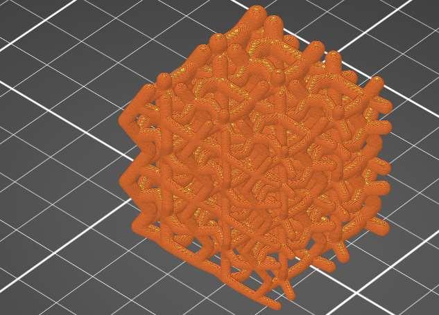
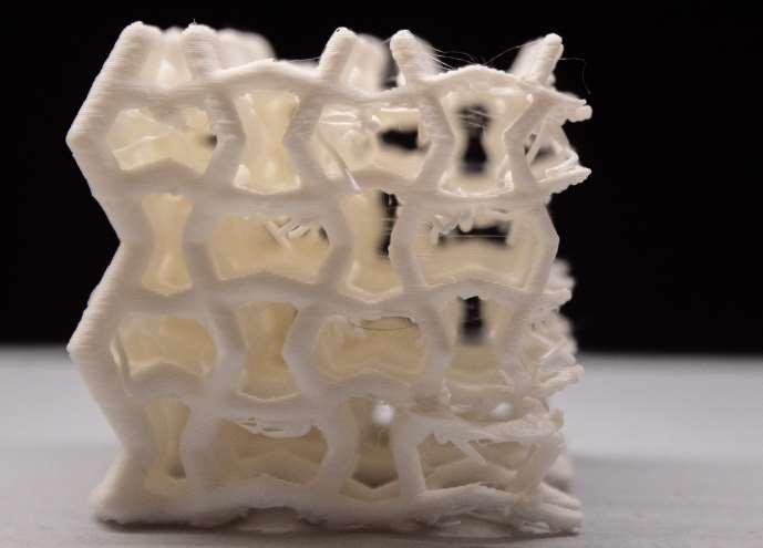
For this unique print, a grasshopper script was used to create a box structure to form lines. These lines were given thickness and visualized using various grasshopper plug-ins.
Due to its various thicknesses and complexity, no infill was used to print this model. The scale was also reduces by 50% to speed the printing process.
Potential Issues
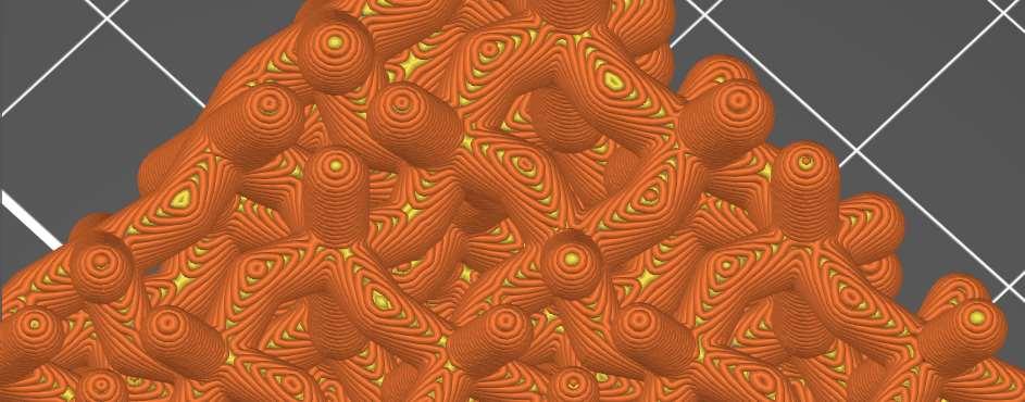
Figure 1. was the first iteration that was printed using the Prusa. Observing the change in gradient shows the strength that the model held during the printing process. The small lines due to the gradient seemed to collapse during the printing process.
Figure 2. was created starting from a thicker output. Although the gradient
was not as visiable as Figure 1. This shows how how the model was able to support
In both models, an issues with stringing appeared. This was most likely caused the the temperature of the 3D printer, as well as the proximity of different lines to one another. Another issue might have been due to the tight design due to
the tight design due to the print being scaled by 50%.


Potential Issues
Before sending the model to print, an issue was noticed. The Prusa app had not overlapped the 3D printed lines. This was a concern as this would mean the structure of the printed model would not be stable as the PLA would not lap on top of one another. After sending to print with this in mind, it seemed like it had no affect on both printed models that showed this issue.
This was most likely corrected due to the nozel type that was used, along with the smaller scale that the model was printed at. Both models showed complete overlap after the printing process.
Finished Models
Takeaways: Before printing, ensure that line thickness can support the model. Due to the complexity of the model, objects like these should be printed when given a large amount of time to use the 3D printer. Scaling down the size of the model can lower the amount of time that is needed to print the model, however this can affect the stability of the
model. If a print like this is necessary, ensure that you watch the model carefully to ensure that the print holds together. This can shorten the amount of time it needs to print, restarting before the model finishes.







Tolerance Testing, Modular Assemblies

Tolerance Test
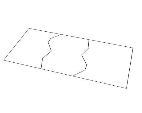
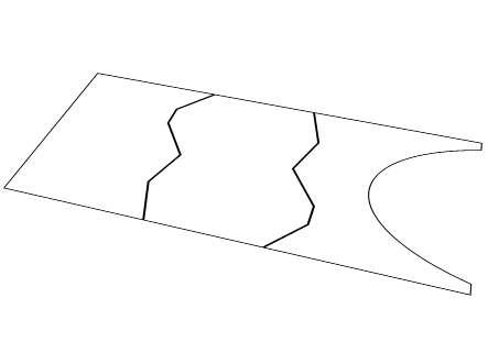
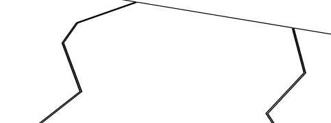
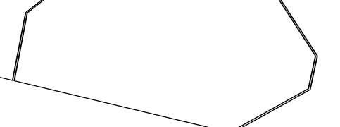
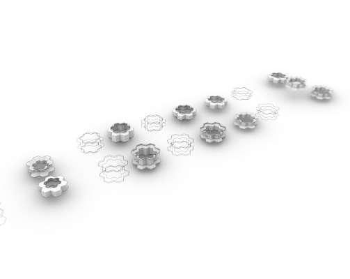
In order to test how the 3D printer handles interlocking shapes, a rectangle was created in Rhino. Lines split the shape using unique patterns. Using the offset tool at the split lines at a 3mm, it created a tolerance for the 3D printer to create the shapes with tight joints

Finished Models
Takeaways: Compared to the previous prints in the class, this model has a strong outer shell and base. This meant that I could remove raft layers, which are meant to help support models with smaller bases. Since the model was solid, this mean that the infill pattern and density could be changed in order to reduce the printing time it would
take for the model to be completely finished. Overall, the 3D model came out clean. The 3mm offset created a smooth interlocking system between the printed models.


Modular Interlocking System
Using Rhino, many different interations were created to find an interlocking modular design that could be printed at both small and large scale. I closely experimented with the idea of a honeycomb inspired system
1_ Rhino Process Work
2_ Rhino Process Work
3_ Rhino Processwork


First Interation
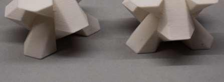
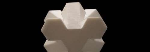
This is the first itneration of the honeycomb interlocking modular design. This design connecting outer and inner line work together to form diagonal slopes together. The line of thought came from trying find a smooth locking system that could lock when extrusions where placed together.
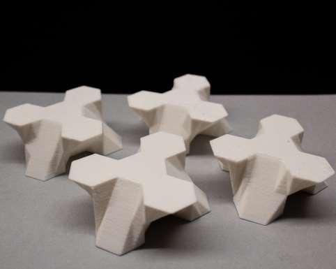
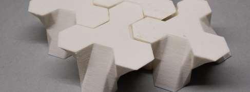
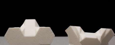
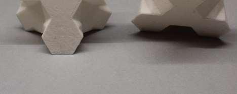
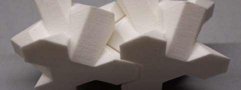
This was the first print of the honeycomb modular system. Although the Rhino model looked similar, Prusa’s model reader changed how certain faces of the model were being built. This was a discrepency that changed how well the model joined together. A good lesson on double checking how pieces should be check in the Prusa
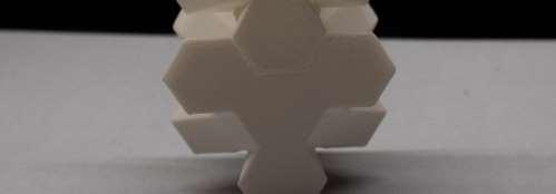
The printed interation also showed the physical reality of the model. The pieces could not be stack vertically and pieces did not lock as well as intended. This lead to a redesign approach on how the interlocking system might occur
1_ Printed Model, Separated 2_ Printed Model, Joined 3_ Printed Model, Standing


Resolving Errors
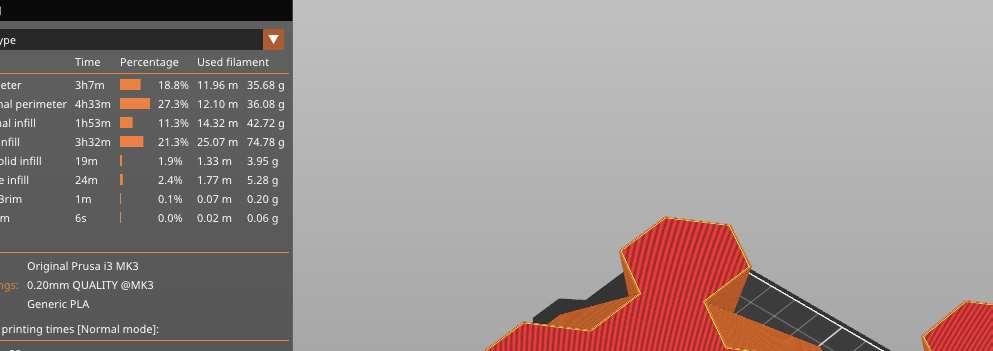
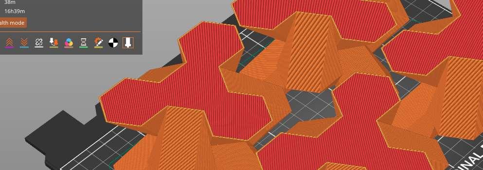
In Figure 1, you can see how the Prusa read how the model was built different depending on the sides of the slopes you look at. However, in comparison of Figure 2, the models look exactly the same. After redrawing the model, it seemed like it was due to the order the faces were drawn in using Rhino.
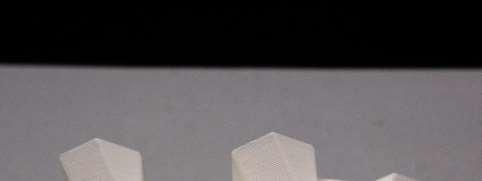
Due to the previous error of Prusa’s model reading from Rhino, multiple test prints were made to ensure the scaling of the model would not effect the quality and interlocking system of the mode. This was the first test print at a small sized scale.


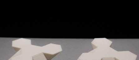
Second Iteration
In order to make the interlock system better, I stacked the model together. This made a strong groove for the models to lock together with. I had remade the original model in hopes that the prusa app would fix the printing on the model. This had resolved the visual error and printed all side the same
1_ Printed Model, Version 2
2_ Printed Model, Stacked
3_ Printed Model, Joint Lock


Testing Multiple Modules
8 medium scaled modules were printed to test different arrangements. Each module is sized to be around 5” x 5” x 3”. The prusa printed four models at a time, Taking 16 hours each batch with a 5% infill rectangular pattern
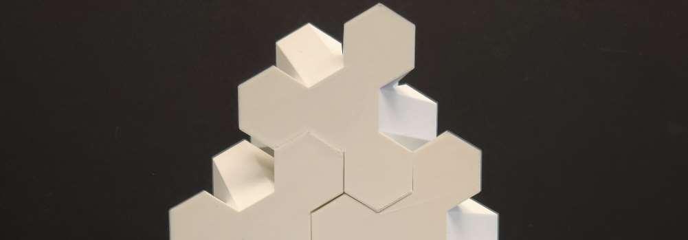
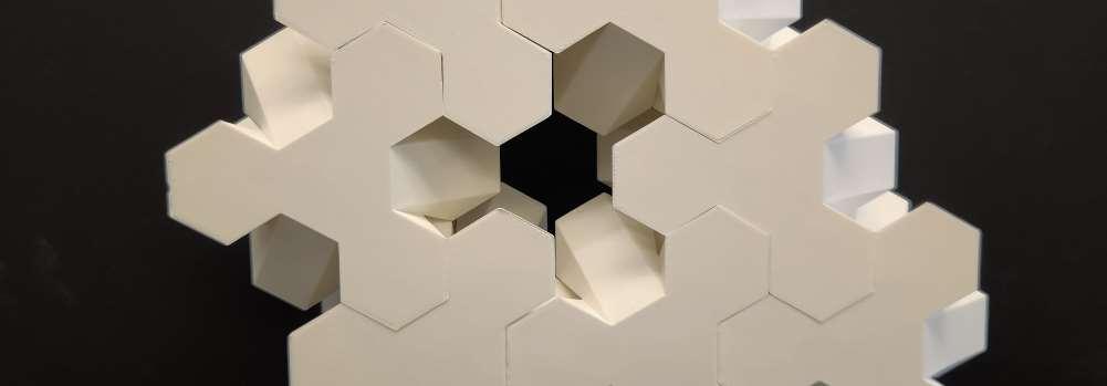


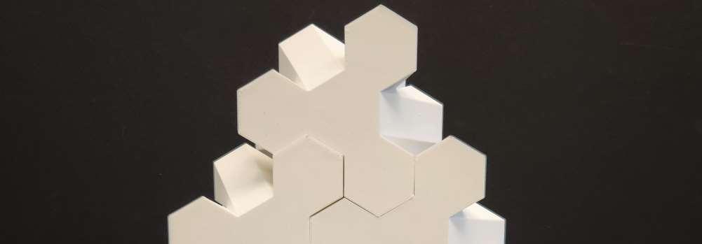
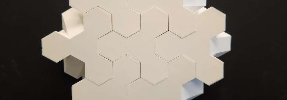
2_ Printed Model, Configuration 1
3_ Printed Model, Configuration 2


During the second batch of printing, an error occurred on one of the models. A corner piece warped during print, causing the smooth edge to curve upwards. This cause this specific corner of the model to not able to connect with the other modules. This warping is most likely caused by the prusa’s bed heating. This specific model was printed
near the edge of the printing bed. The difference between the center of the bed versus the cooler side of the edge of the bed caused this warping.


Large Iterations
These larger models were scaled to be 7” x 7” x 5”. Each module took around 15 hours to print. Despite the size of the model as well as it taking the entire prusca bed to print, there seemed to be no major printing issues.


