MODULE 1
DIGITAL DESIGN TO 3D FABRICATION
The form of this print stemmed from a series of six circles evenly spaced up a four inch line. Each circle with the exception of the base was rebuilt with a set of 10 points. The circles were manipulated to form a rounded pentagon shape, rotated alternating directions, and scaled differently to create an undulating curved shape that serves as the walls of the vase.
Going back and forth between the Rhino workspace and the slicer, small adjustments were made to prevent gaps in the walls caused by too extreme of a rotation at the base. After a few attempts and rounds of manipulation, the initial curves at the bottom of the vase no longer separated from the base.
The printer used to create this print was the Bambu Lab X1C, resulting in a relatively fast print at around 35 minutes, due to the technology of the printer and the single wall thickness of the vase.
1_ Initial form linework
2_ Lofted geometry from linework
3_ Sliced geometry
4_ Vase model photo
5_ Vase model photo, top view
6_Vase Model Photo
2_
3_
4_
5_
fig. 4
fig. 5
fig. 6
1_ Initial form linework
Lofted geometry from linework
Sliced geometry
Vase model photo
Vase model photo, top view
6_Vase Model Photo
7
Initial ideas for the form of the wall started from a series of points connected through lines to create a set of polygons. The linework was mirrored to create a symmetrical wall. The polygons were extruded and pushed and pulled to add a sense of dynamism to the form.
The printer used to create this print was the Original Prusa i3 MK3.
The print itself had no foreseeable errors with the exception of the points and valley at the top of the wall. The slicer preview showed a fairly noticeable gap in the center and smaller gaps at each point. However, the print went smoothly and the gaps were filled in the printing process.
7_
8_
9_
10_
11_
workflow process
Diagram,
Initial digital model
Sliced geometry
Wall model print
Wall model print, top view
WALL PRINT
8_
fig. 10
fig. 11
7_ Diagram, workflow process
Initial digital model
9_ Sliced geometry
10_ Wall model print
11_ Wall model print, top view
13
14
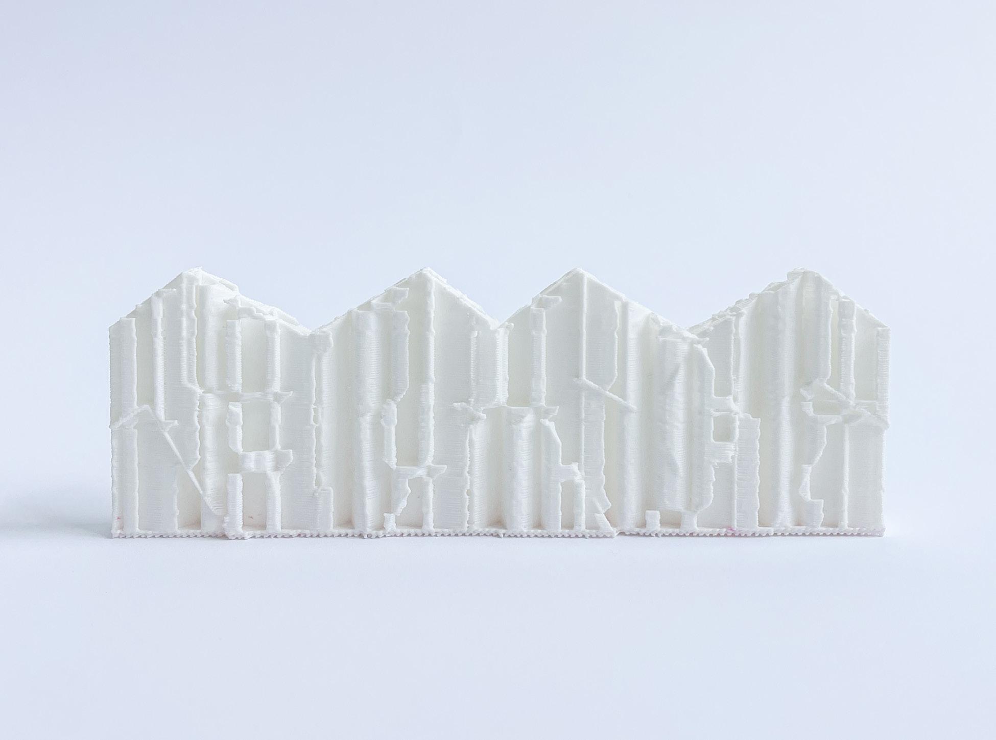
Taking the same wall geometry previously generated and mirroring it, a larger wall to test the scale of infill and capacity of the printer was created. This first pass at the infill print was see how the infill would fill in the varying extrusions in the wall as well as its stability.
In the slicer print settings, the perimeter fills were all set to zero
with the infill density set to 20%. The infill pattern used for this print was the triangles.
The Prusa printer, same as the previous print, was used. No major failures occurred during the print. Aesthetically, however, the print looked as though the filament had melted together in some areas and does not have very “clean” edges.
Though the scale and temperature at which the print was set to prevented any stringing with the filament.
12_ Infill pattern and density
13_ Initial digital wall model
14_ Sliced geometry
15_ Wall infill model photo
16_ Wall infill model photo, top view
fig.
fig.
fig. 15
fig. 16
12_ Infill pattern and density
13_ Initial digital wall model
14_ Sliced geometry
15_ Wall infill model photo
16_ Wall infill model photo, top view
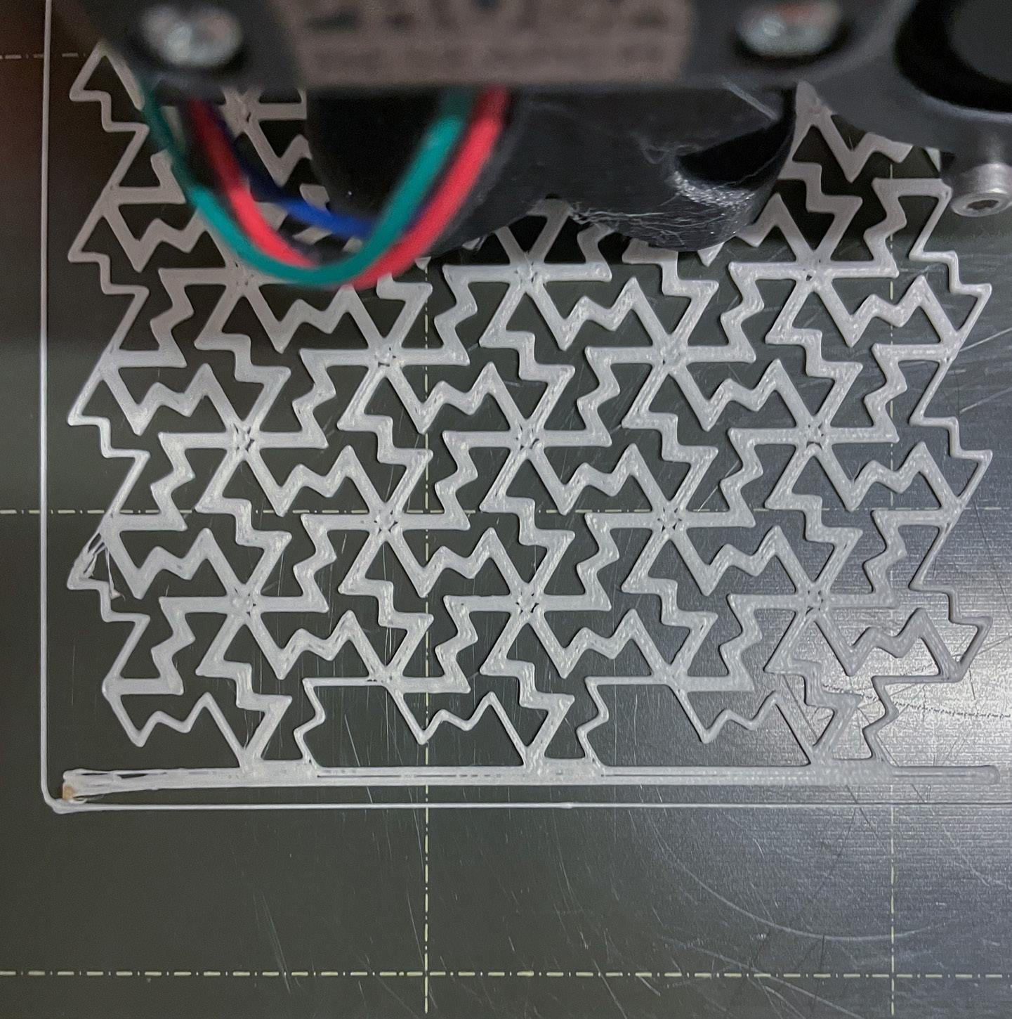
Reverting back to the initial, smaller wall shape, a different infill density was tested to see if any of the aesthetic issues would be solved
The same printer was used as before, however the infill settings were altered slightly with a density decrease from 20% to 5%. The same infill pattern was used.
The finalized print ended up with a set of new issues not encountered with the previous iteration. The distance of the peaks in the wall created some stringing between. There was also some mild pulls in the filament around other areas of the infill pattern. Overall, this print was far more delicate, most likely due to the lack of density and single thickness wall.
17_
18_
19_
20_
21_
Infill pattern and density
Initial digital wall model
Sliced geometry
Wall infill model photo
Wall infill model photo, top view
fig. 17
fig. 18
fig. 19
fig. 20
fig. 21
17_ Infill pattern and density
18_ Initial digital wall model
19_ Sliced geometry
20_ Wall infill model photo
21_ Wall infill model photo, top view
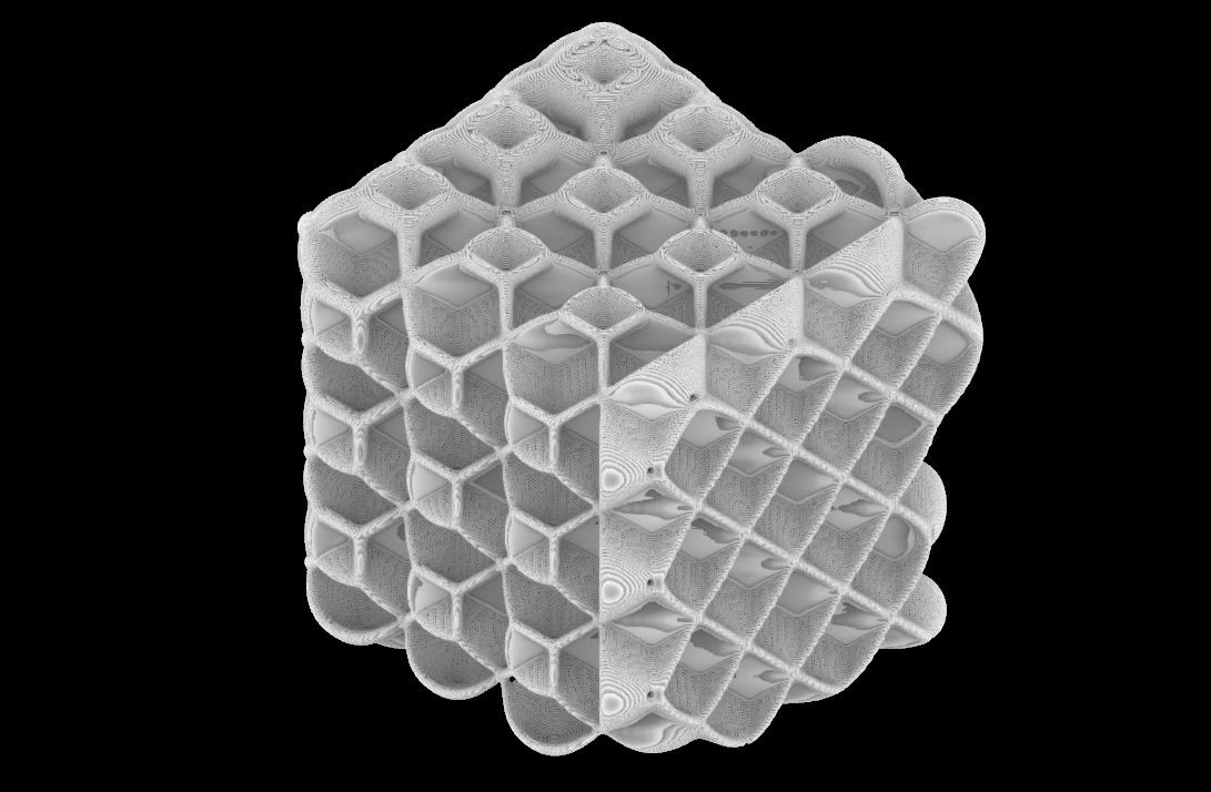
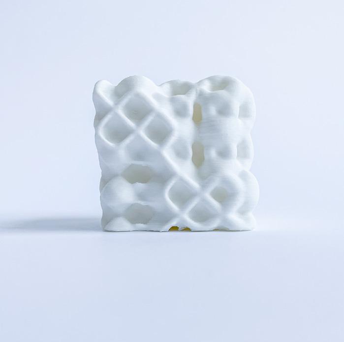
To create the initial form for this print, Rhino Grasshopper using plugins Dendro, Pufferfish, and Crystallon, started with the initial boundary representation of a 4”x4” cube. The dodecahedron shell infill option was used to generate the curvature and 3D pattern repetition inside the cube. The dodecahedron infill pattern alternated both inside and out, beginning with diamond-
like shapes that evolved into cubes and back. This, combined with a gradient pull generating thicker to thinner forms, not only created an interesting, complex geometry on the inside, but allowed for a unique surface on each side of the cube.
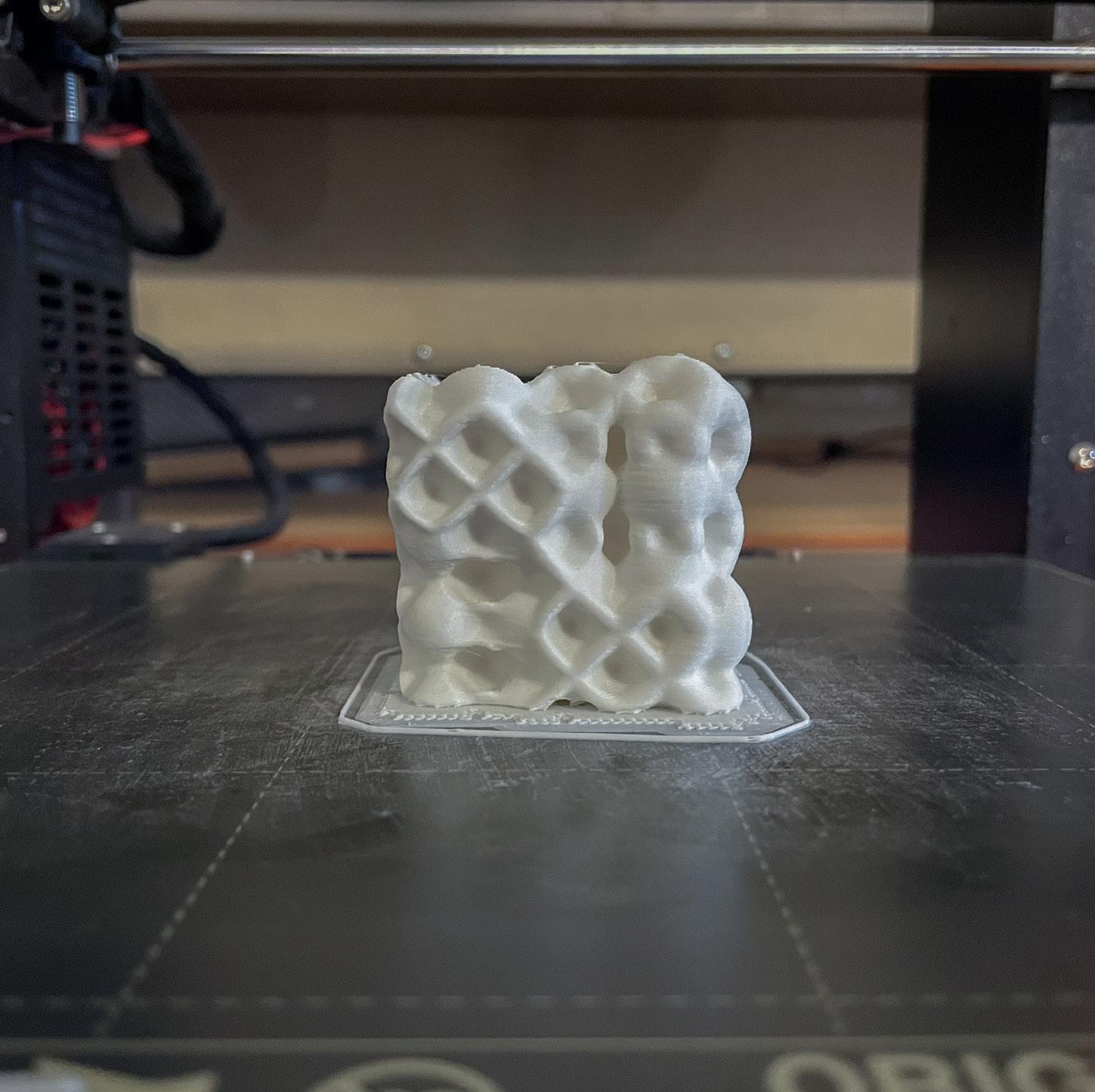
Due to the surfaces along the cube, the object was not flush with the ground plane. As a result, the
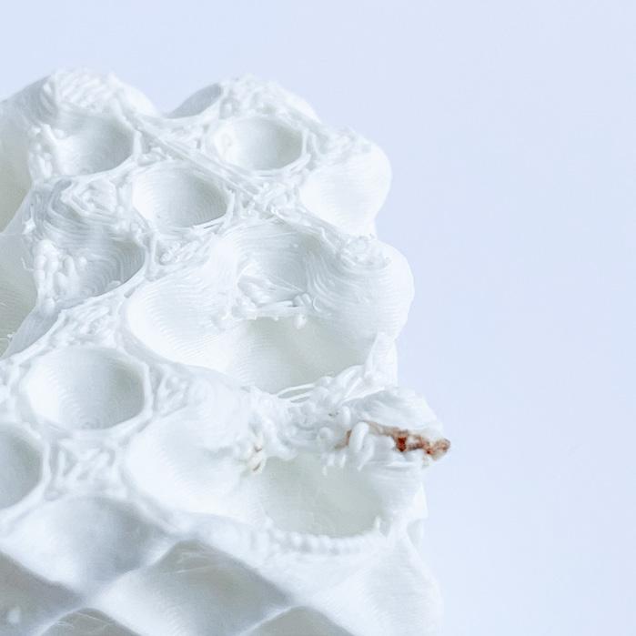
geometry needed to be pulled down in the slicer in order to maintain a stable base. However, one corner of the gradient cube was not touching the plater which caused a slight failure. This ended up being a minor obstacle and the rest of the fourhour print went smoothly.
22_ Gradient pattern geometry sections
23_Initial boundary representation
24_Digital model
25_ Sliced geometry
fig. 23
fig. 22
26_ Model photo, side view
27_ Model photo, side view
28_ Model photo, side view
29_ Model photo, side view
30_ Model photo, top view
31_ Model photo, zoomed into partial failure
32_ Model photo, texture
MODULE 2
CONNECTIONS AND MODULE DESIGN
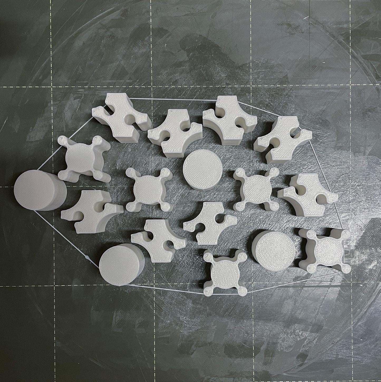
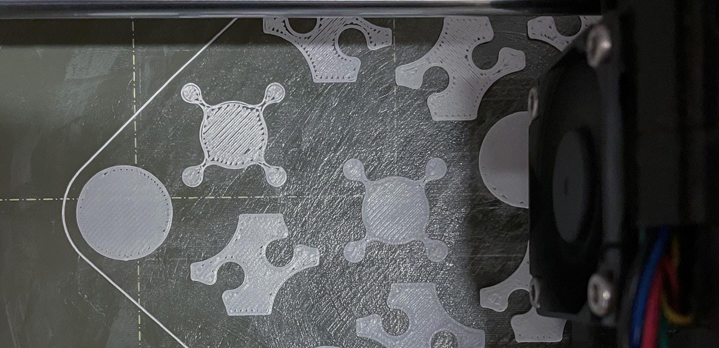
This module focused on creating a set of interlocking shapes to test the offset tolerance to be able to fit together. To accomplish this, a repeating pattern was formed from a series of rectangles and circles which created a set of puzzle-like pieces that slide and lock together. The curves were trimmed and joined to created individual shapes which were then offset in either
direction by 0.15mm, 0.3mm in total, to allow for a slight gap in between each object. The curves were then extruded to generate a threedimensional form to be printed.
Once the geometry was imported into the slicer, the pieces were individually spaced further apart to prevent any potentially bleeding or merging during the printing process.
The print ran smoothly with no errors. The final model was fairly loose-fitting and the tolerances between could have been smaller. A lower tolerance or offset of curves and shapes will be explored in further iterations.
33_ Pattern progression diagram
34_ Digital model of curve extrusion
35_ Sliced geometry
fig. 33
fig.
fig. 36
fig. 37
fig. 38
36_ Model photo, top view
37_ Model photo, side view
38_ Model photo, tolerance close up
The initial idea for a series of modules that lock together was created through a pattern generated by the Grasshopper plugin Parakeet. The boundary shape was a hexagon which was then populated by zig zag lines to form the base geometry. To create a void in the center, the module was identified from the lines joined, then offset. The loft command in Rhino was used to get
a tapered edge on the interior sides of the shape. The exterior walls were left perpendicular in hopes of creating a tight fit between modules.
To connect the modules, a set of solid and voids were placed around the form to lock into one another. This shape was rectangular and was offset 0.08mm to allow for a slight gap or tolerance in the printing
process. Each rectangle is 5mm tall, 8mm long, and 2mm wide. These were placed alternating solid and void around the three “sides” of the geometry.
39_ Hexagon boundary
40_ Pattern fill
41_ Pattern
42_ Pattern module
43_ Offset 44_ Extruded geometry
Overall form 46_ Connection close up and dimensions 47_ Axon of connections and geometry
fig. 45
fig. 46
fig. 47
There were no issues in the printing process. The geometry was relatively simple with no major overhangs or bridging, resulting in a clean print.
The tolerance between the two modules proved to work well. The modules tightly snapped together, however the male and female connections are fairly small and will
be made larger to accommodate a larger scale moving forward in the design process. 48_ Rhino geometry
Sliced geometry
fig. 48
fig. 49
fig. 50
fig. 52
fig. 51
50_ Model photo, top view
51_ Model photo, tolerance close up
52_ Model photo, connection side view
The final module design took the prototype geometry, modified the connections, and added a mesh to the interior of the same pattern the module was generated from. To create the geometry for the mesh, the initial pattern was offset and turned into a solid using the mesh pipe component in Grasshopper.
The pipes were cropped to the interior with a slight overlap with the bottom of the exterior walls to ensure adhesion when printing. Two layers of the pipes were placed on the interior for varying thickness.
These modules were printed on the Bambu X1 Carbon printer. This allowed for a higher precision of printing for the interior mesh as well
as the tolerances between the connections. The print time for each module was 2 hours and 8 minutes.
The four modules printed had few issues between the connections. The scale however, makes it slightly difficult to get the modules to lock together. Though when they are connected, the modules are tightly secured.
53_ Interior mesh geometry
54_ Final geometry of modules
55_ Exploded axon of pattern layers
fig. 53
fig. 54
fig. 55
57_
58_
59_
fig. 56
fig. 57
fig. 58
fig. 59
56_ Model photo, four modules
Model photo, connection close up
Model photo, tolerance close up
Model photo, single module
MODULE AT ARCHITECTURAL SCALE
The architectural application for this module is thought to be either a screen for shading or a partition wall.
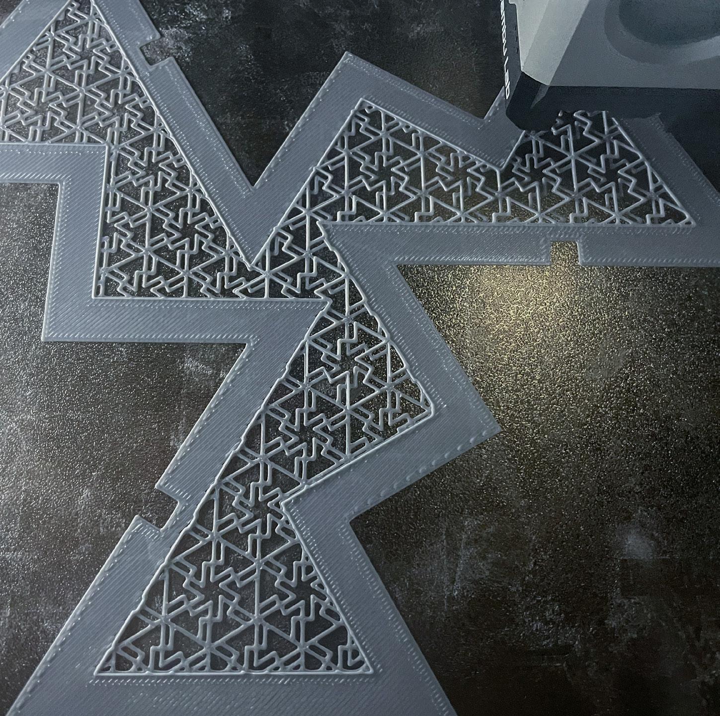
A partition-like wall was printed at 1”=1’ architectural scale. Due to the delicate, thin nature of the geometry, the print was not as smooth or precise as previous prints. The printer used to fabricate this was the
Prusa i3 MK3. The bed adhesion during this print was weak. A few lifts occurred after the first pass of filament, one at the base and a few dispersed throughout the wall.
As a result of monitoring this design at this scale printed on the Prusa, the mesh fill of the full scale module would be incredibly difficult to achieve with these printers.
60_ Screen application
61_ Exploded axon of screen to window
fig. 60 fig. 61
fig. 62
fig. 64
fig. 63
fig. 65
62_ Model photo
63_ Model photo, close up
64_ Model photo, minor failure close up
65_ Model photo, minor failure base close up


