
1
MODULE 1
Vase pg 6
Infill pg 8
Gradient pg 12
2 MODULE 2
Tolerance Test pg 18
Modular Assembly pg 20


Vase pg 6
Infill pg 8
Gradient pg 12
Tolerance Test pg 18
Modular Assembly pg 20

DESCRIPTION
VASE PRINTING
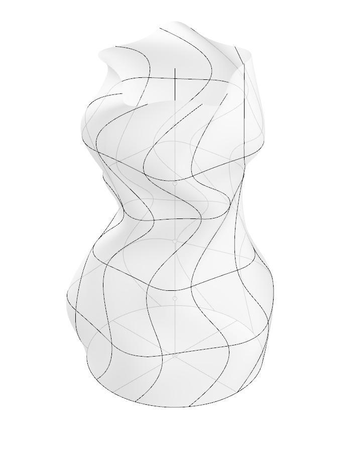
To create this case, we started off by creating six circles along one line in rhino. Then we manipulated five of these circles and lofted the shape. This create the organic form in the second image. After thats we capped this object exported it as an stl file to process in the 3D printing software. In ether bambu or Prusa we then loaded in this model from Rhino. One key thing to do is to set
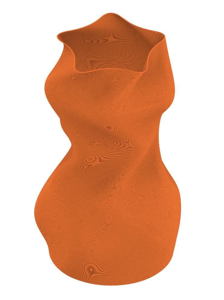
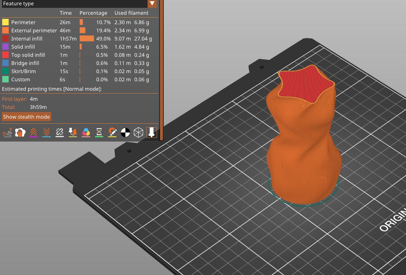
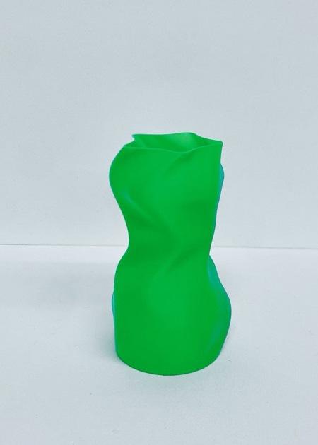
the 3D printer setting to have vase on. This will tell the printer to only form a perimeter. This results in the tool path being created, as seen in the third image. Finally check the printing preview and ensure that there are no issues with the print. Then load the g-code into a printer and print. The final result is seen in the last image.
1_ Rhino, line work
2_ Rhino, 3D Model
3_ Rhino, tool path
4_ Prusa, Print preview
5_ Picture, physical model

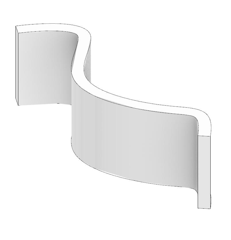

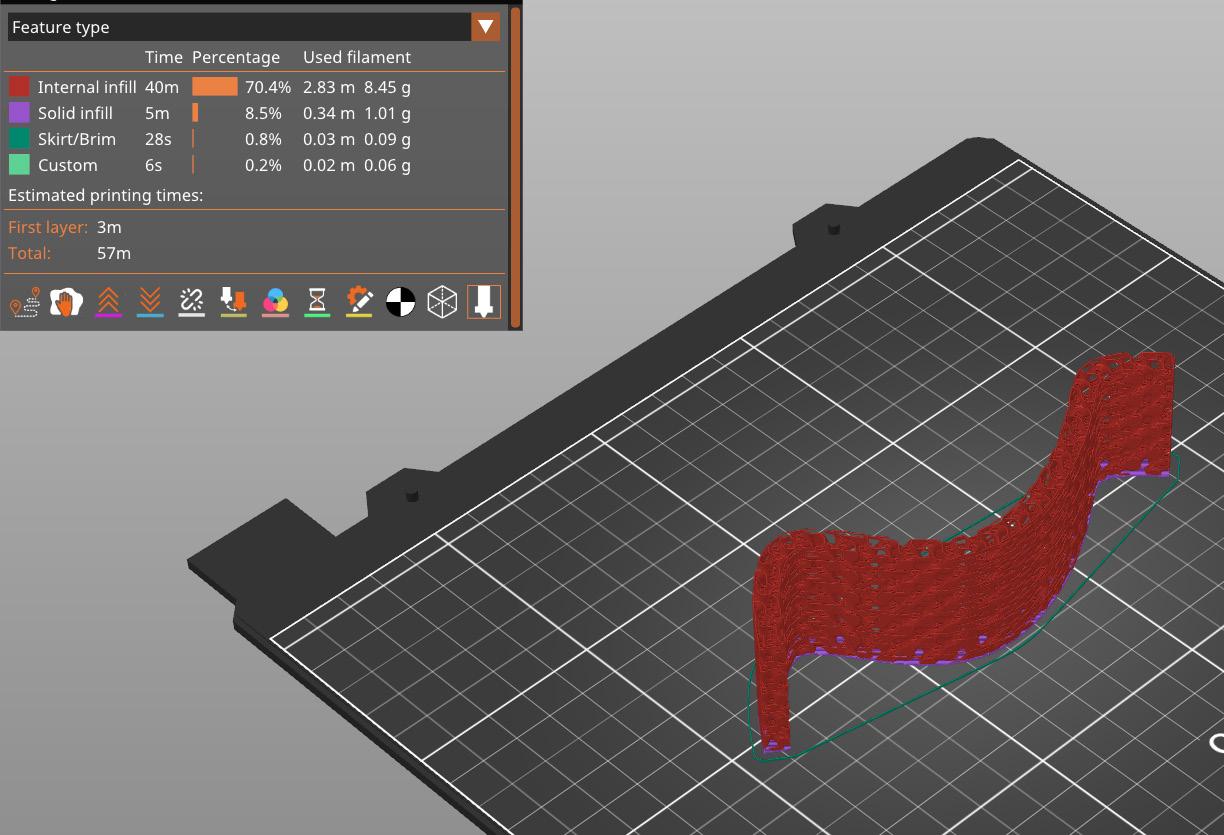
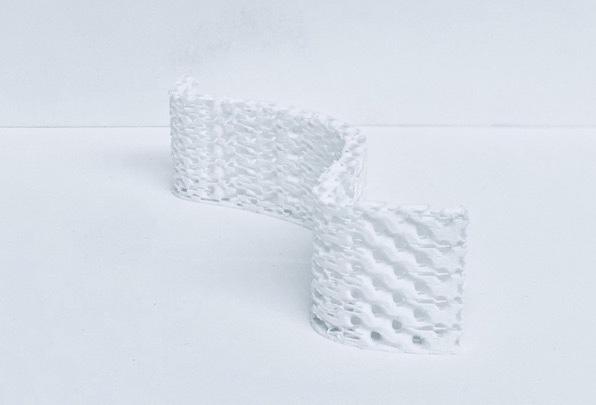
This projects started off by created a curved line. Off set this line by a minimum of 3/8” as that is the minimum required distance for printer to infill. Next close off this shape and join the lines, then extrude the shape and create a wall. After that export the stl into the prusa printer. The tool path of this object is seen in the third image, this allows you to preview the print.
Ensure that there are no printing issues highlighted by the print preview in prusa and then export the g code and load it into a Prusa. The final product can be seen in the last image. One thing that was done to create an open top was in the print settings, this lay was taken off.
7_
8_
9_ Prusa, Print preview
10_ Picture, physical model
11_ Rhino, exploded axon

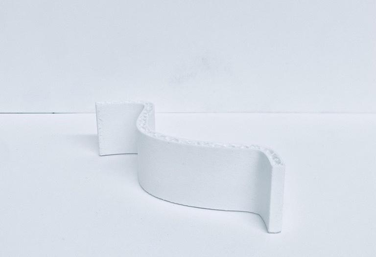
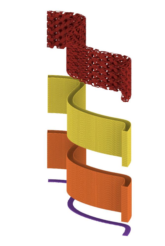


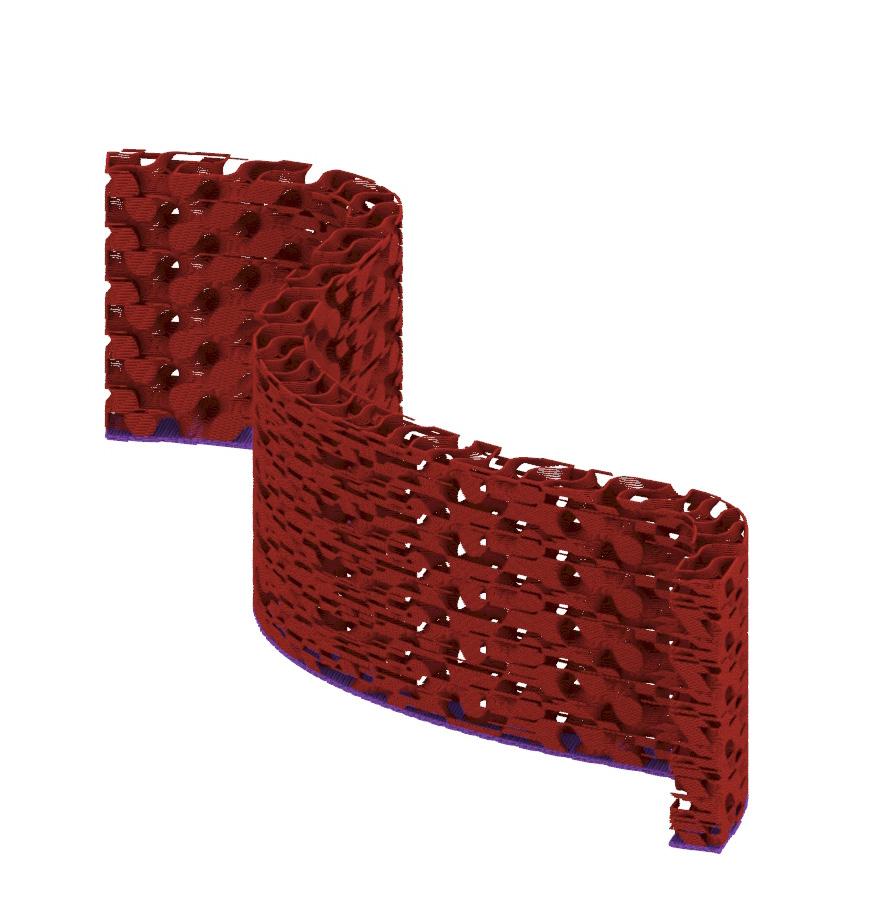
This project started off the same as the previous one, with a line and shape being created. This shape was then extruded and exported as an stl into the Prusa. However, where this project varied was in the print settings. In this set up the top and horizontal fill was tuned off. This mean that the infill would just be printed and not the shell. One thing to note is that to give the infill
something to attach to, I left the bottom piece on. This allowed for the print to be more structurally sound that just the infill being printed. After checking the preview and ensuring there are no print issues export the g-code. After printing the object should look like the last photo.
15_
16_
DESCRIPTION
GRADIENT PRINT 1
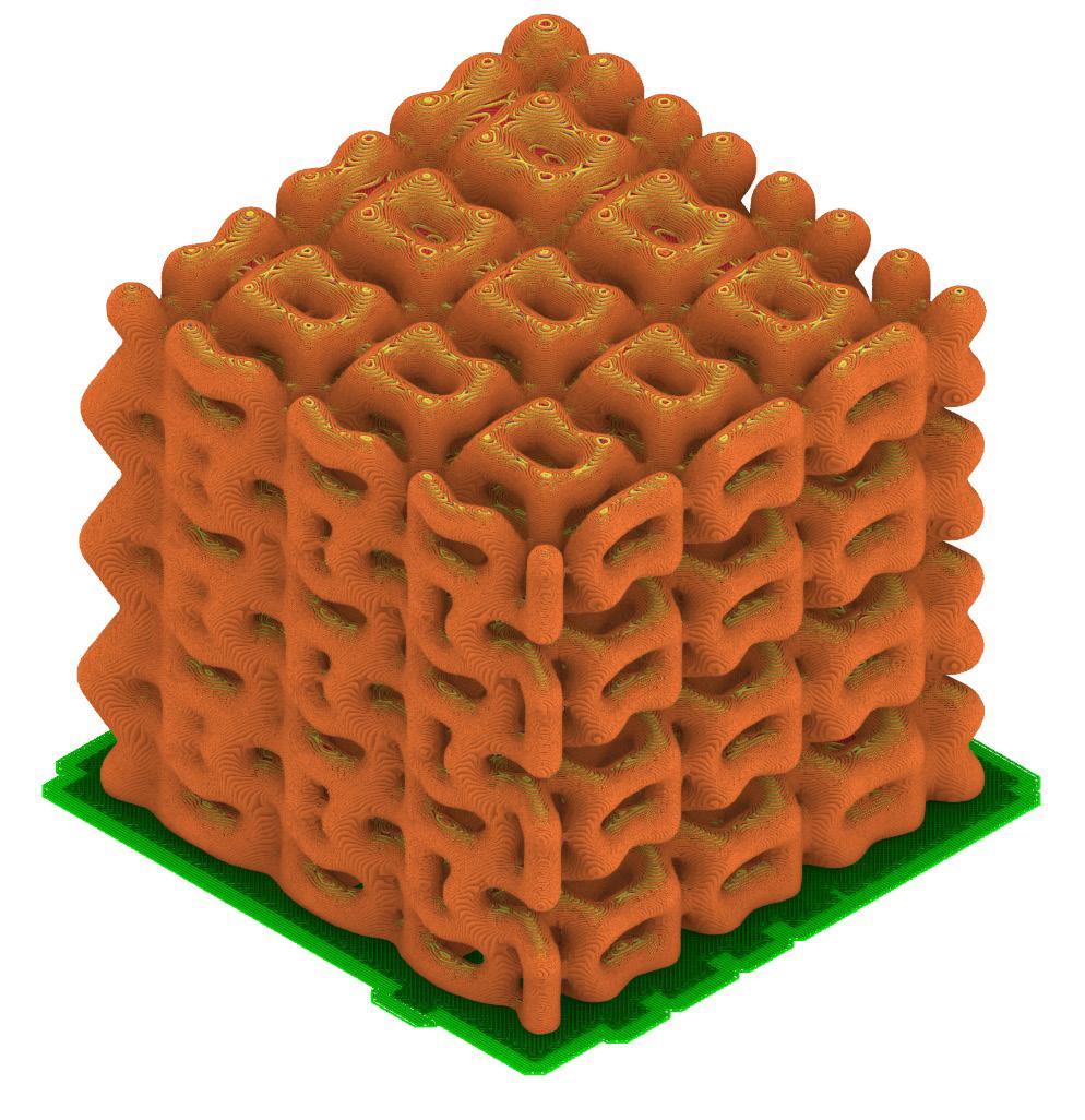
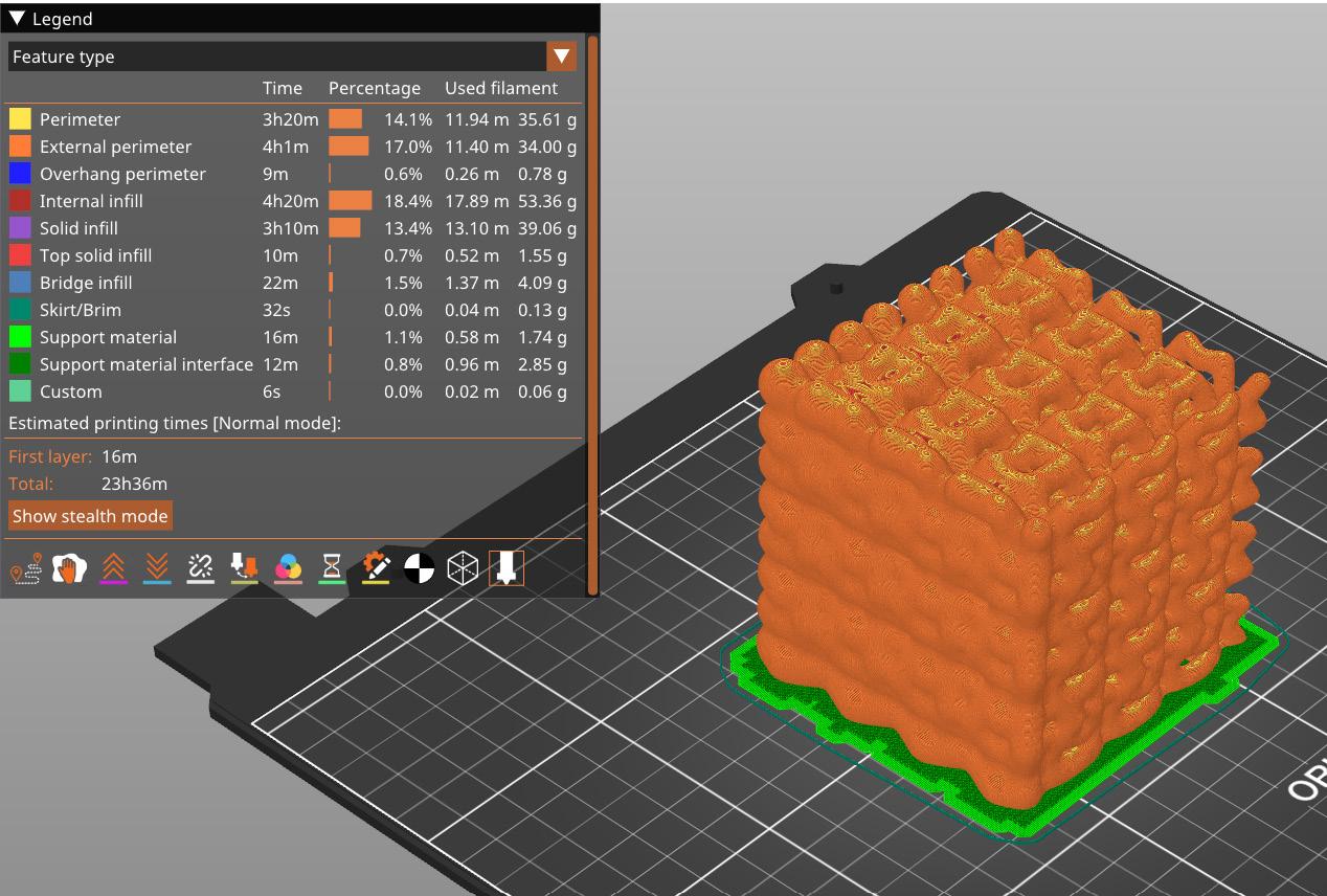
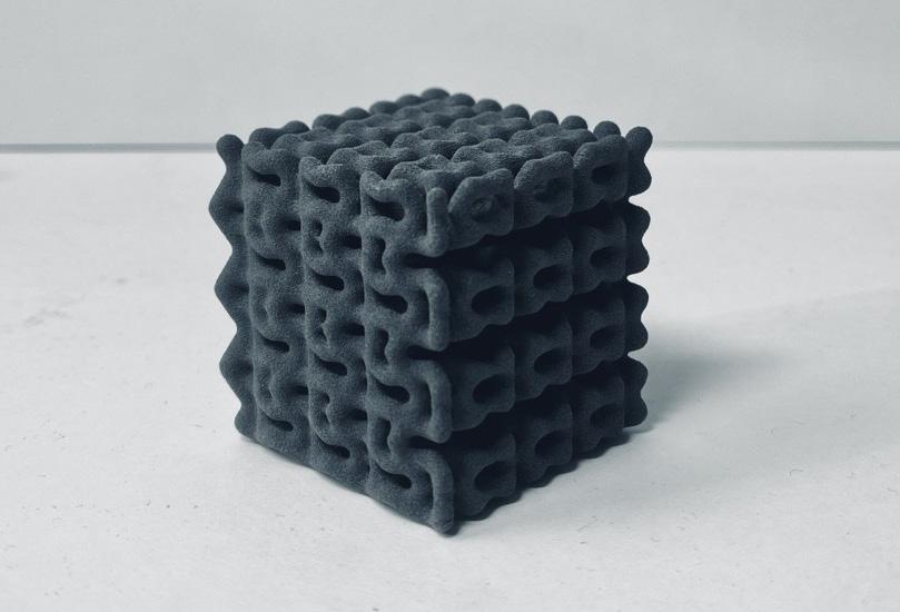
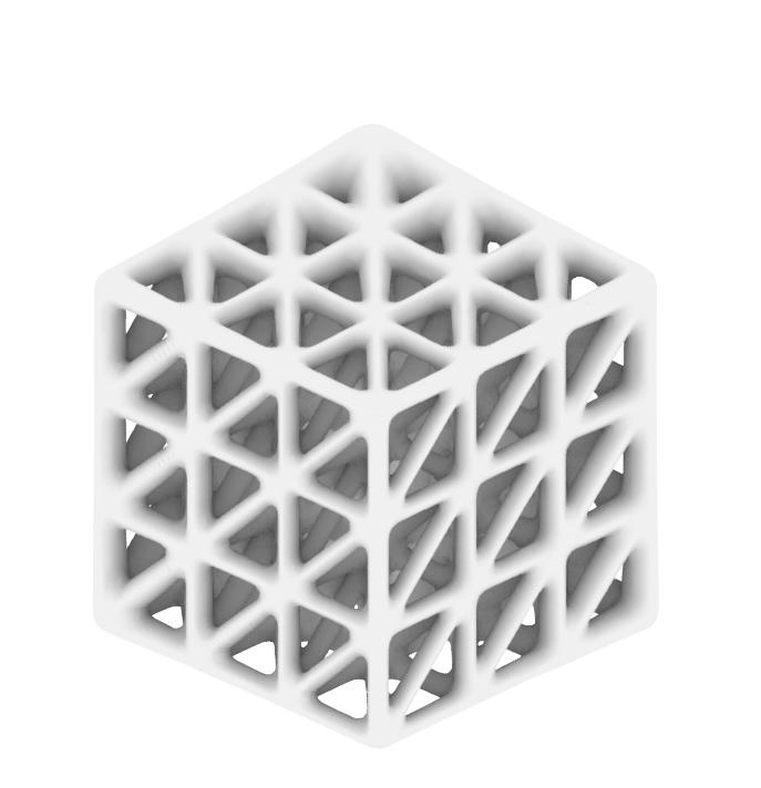
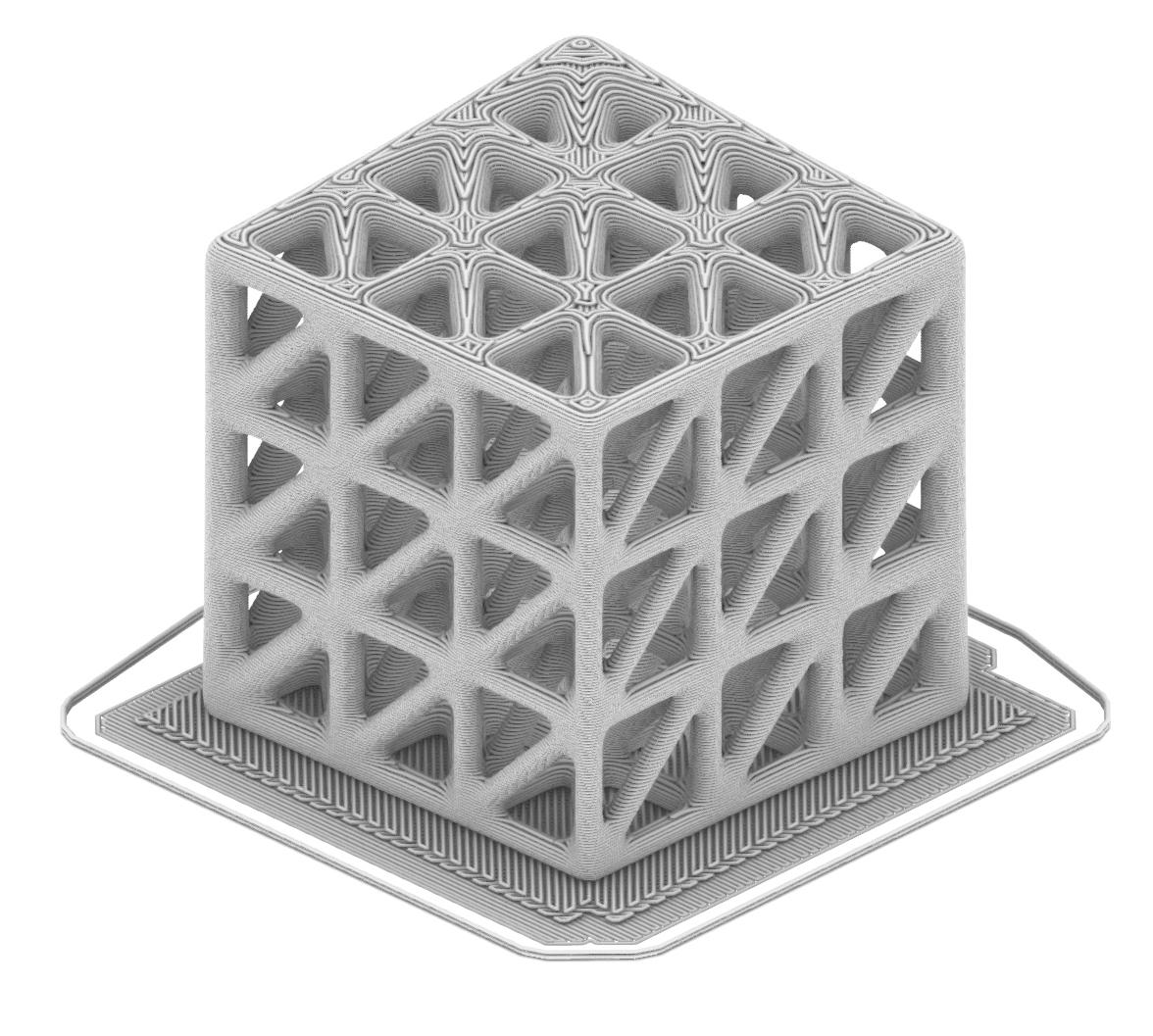
This model started off by manipulating a grasshopper gradient script provided in class. I altered were the thickness of the voxels and the intensity of the gradient. While this print was not printed on the Pursa and was printed on the fuse printer. This allowed for the structure of the model to not be as supported as it would be for the prusa model. If printed on the prusa
the model would need to no longer have any overhangs. Both types of prints would take a day to finish, however the fuse print was printing with the rest of the class.
17_
18_
19_
20_
tool path of iteration
print preview
21_ Photo, 3D printed gradient model
DESCRIPTION
GRADIENT PRINTING 2
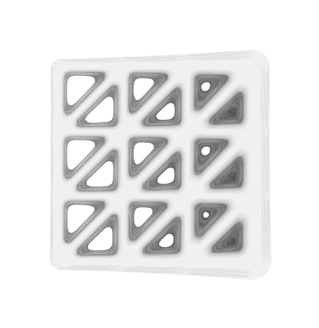
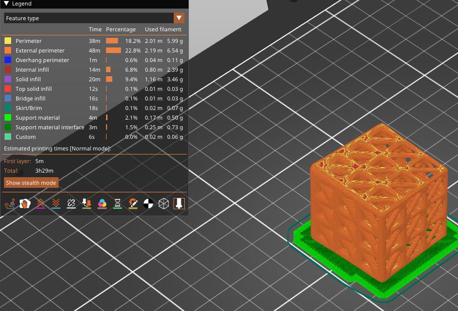
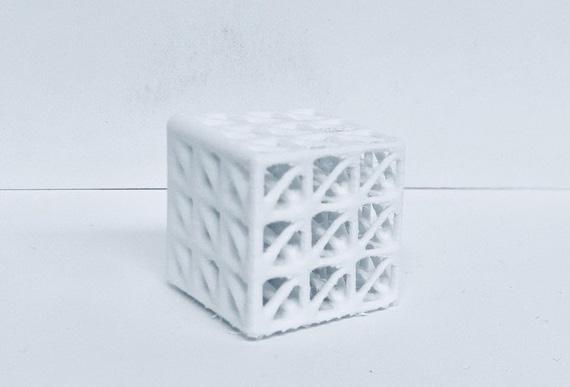
This project ended up differently than the previous iteration. I made this one more simple due to the overhang and significant time it would have taken to print the previous iteration. I manipulated the same features of the grasshopper script in this model. As seen in figure 25 the print time in this iteration was only 3.5 hours compared to the almost 24 hour print time in the
previous one. If this print had to be redone, the speed of the prusa should be decreased to reduce the stringiness of the print.
23_
24_
25_


DESCRIPTION
TOLERANCE PRINT
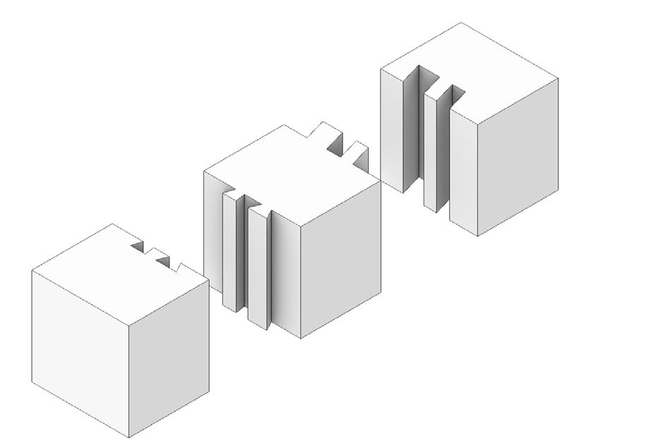
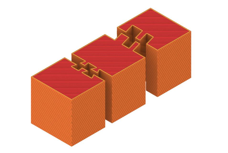
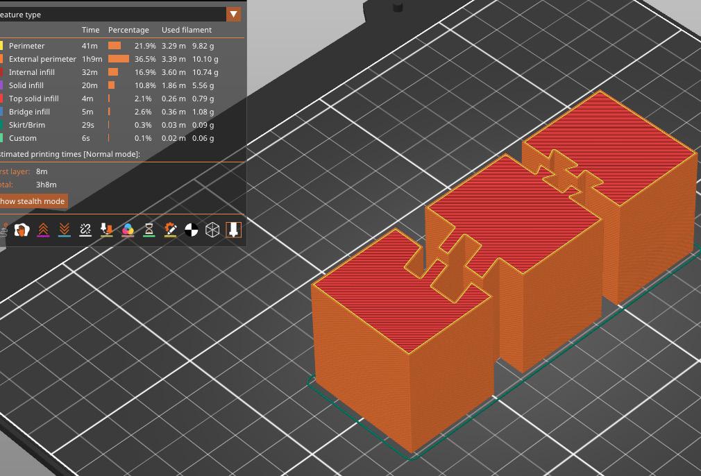
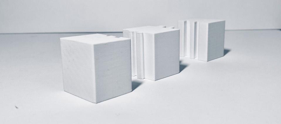
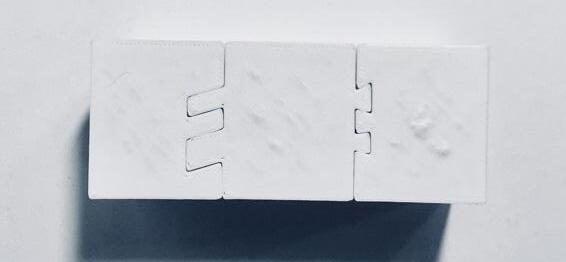
This project started off by creating a rectangle and dividing it equally into three parts. After that create three squares and manipulate the center lines to create interlocking shapes. Then offset those interlocking lines by 0.3 mm to create an acceptable tolerance so that once printing these shapes can properly connect. After that using the curve boolean command in rhino create three
shapes. Next, extrude these shapes, as seen in figure 28 and export this to prusa. Once in prusa print the objects and it should look like figure 31. Some things to note in this project is that the angle for the slanted interlocking pieces could have been more steep to better connect.
27_ Rhino, process for creating the shape
28_ Rhino, extruded shape
29_ Rhino, tool path
30_ Prusa, Print Preview
31_ Photo, Physical Model
32_ Photo, Physical Model
33_ Photo, Physical Model

DESCRIPTION
PARTITION WALL
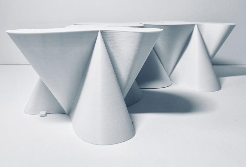
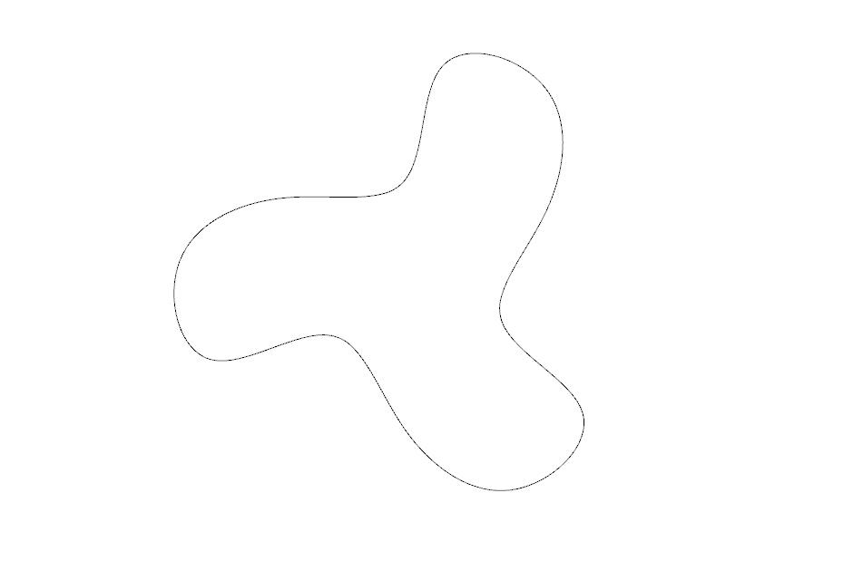
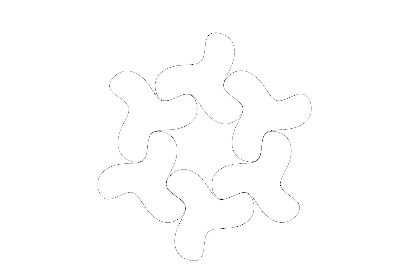
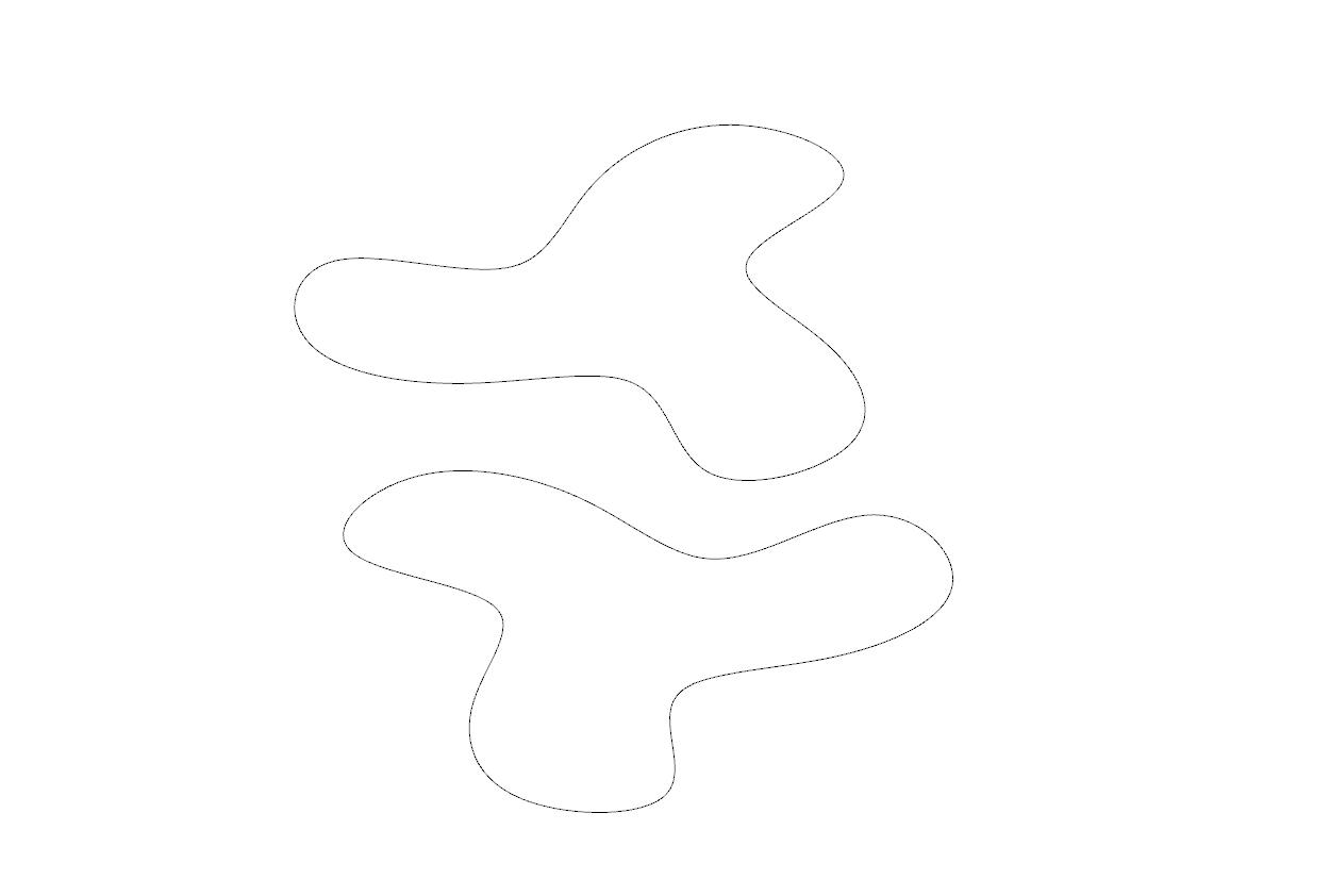
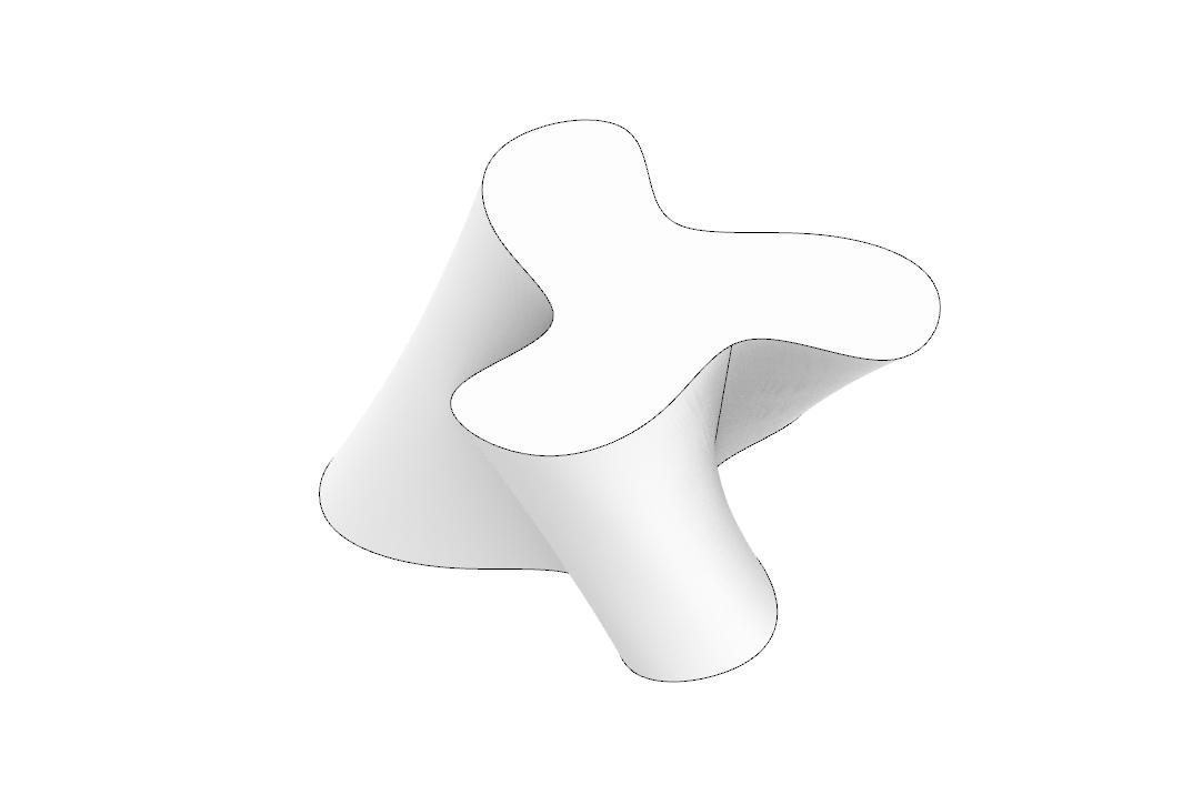
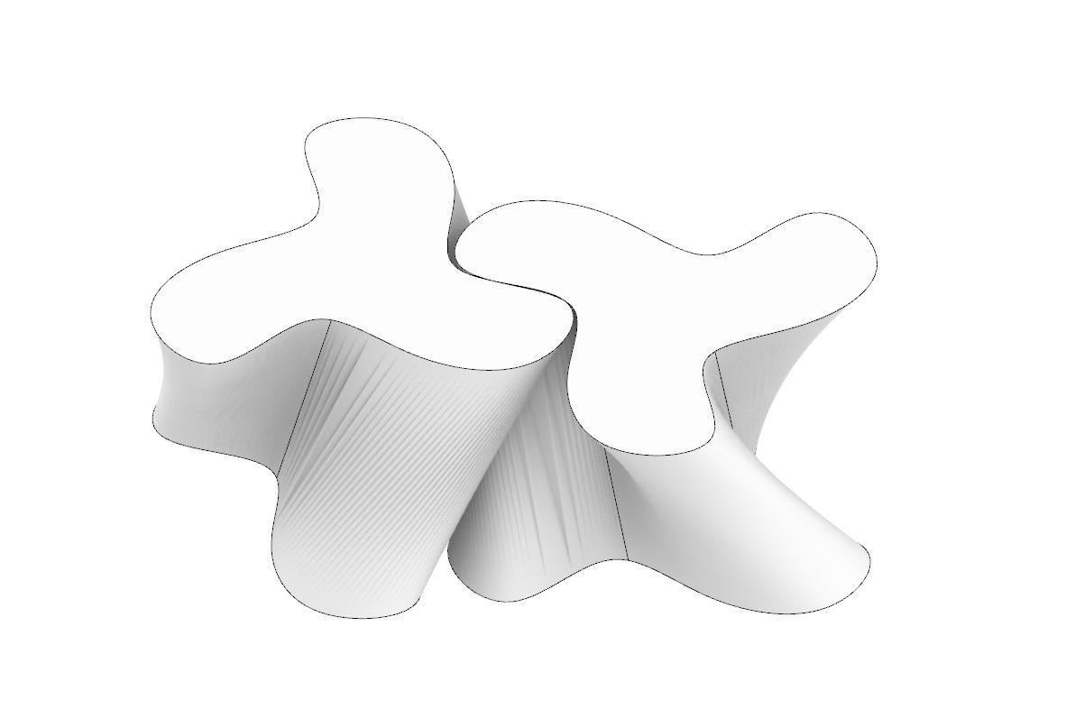
This project centers around using interlocking blocks to create a lattice partition wall. To start this project, I started with a rough outline of the shape I wanted and then rebuilt the curve to create even spacing. I then moved the curve up 1” and rotated by 60 degrees. After that I lofted the curves and caped the shape. This created the shape in figure 37.
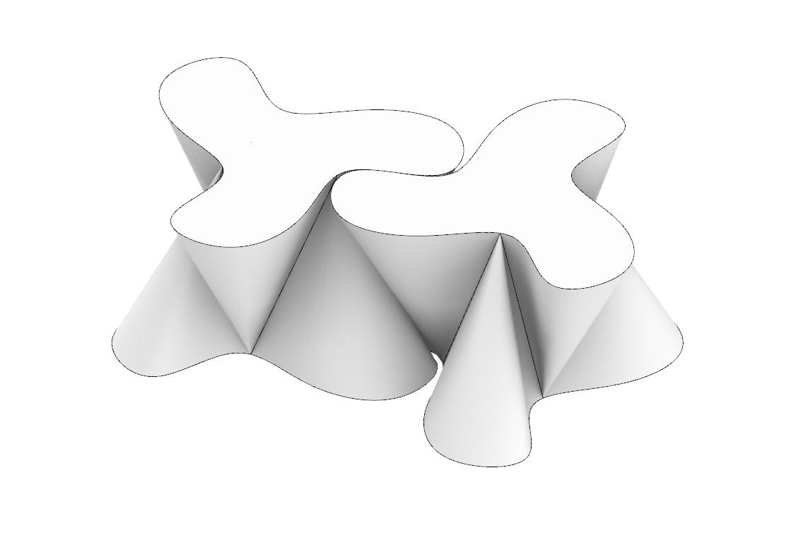
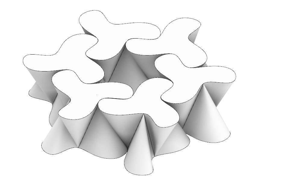
However, as seen in figure 39 this shape did not work as there was a gap in the interlock. This led me to redo the loft and create the shape seen in figure 40. This shape did end up working and allowed me to create the full pattern that will be used to make up the partition wall.
34_ Rhino, Primary Shapes
35_ Rhino, Plan of modular pattern
36_ Rhino, Shape moved up 1”
37_ Rhino, Lofted iteration 1
38_ Rhino, Modular 1
39_ Photo, Test Model
40_ Rhino, Lofted iteration 2
41_ Rhino, Modular 2
42_ Rhino, Modular pattern


34_ Rhino, Primary Shapes
35_ Rhino, Plan of modular pattern
36_ Rhino, Shape moved up 1”
37_ Rhino, Lofted iteration 1
38_ Rhino, Modular 1
39_ Photo, Test Model
40_ Rhino, Lofted iteration 2
41_ Rhino, Modular 2
42_ Rhino, Modular pattern
DESCRIPTION PARTITION WALL
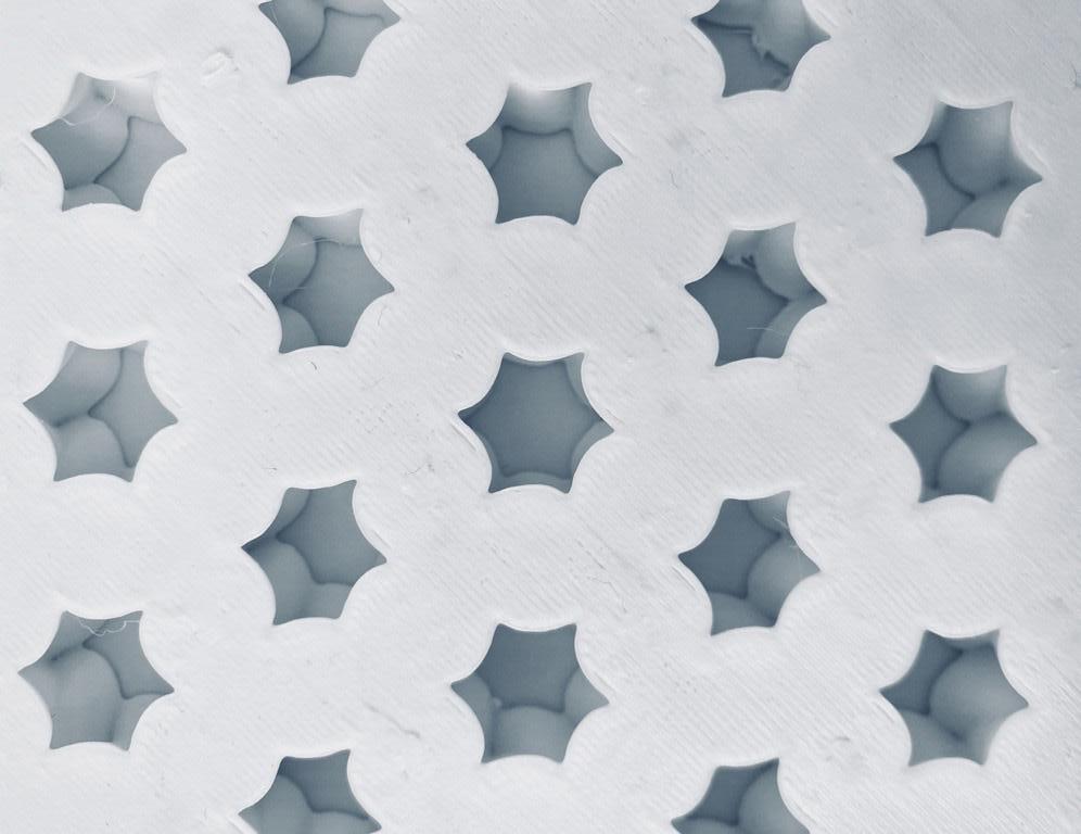
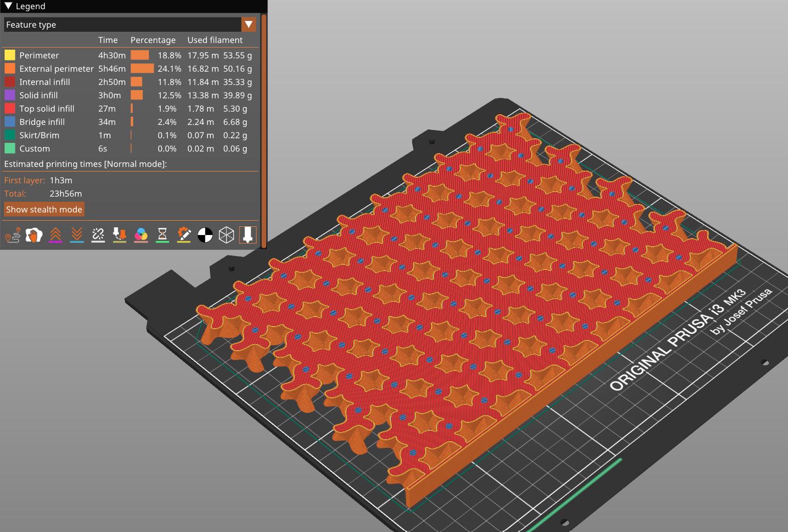
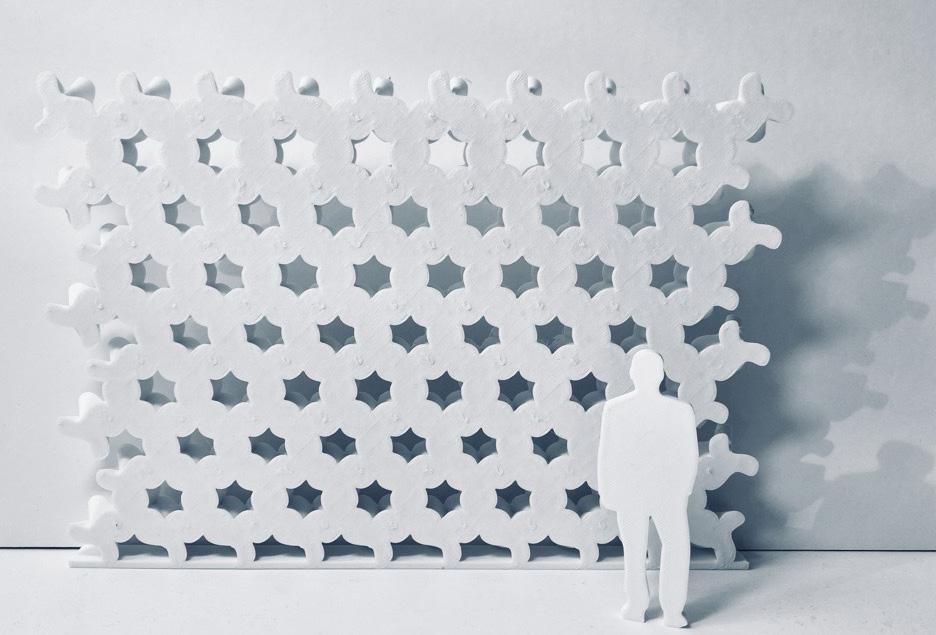
For architectural scale model of the partition wall I chose 0.5” scale. This model consists of the modular pattern stacked on top of each other arrayed in the x direction. The wall is 12’ by 18’. For the final printed model due to time constraints I added a platform for the wall to stand, however it did not need this in the end and would have been able to be supported if not there. The final
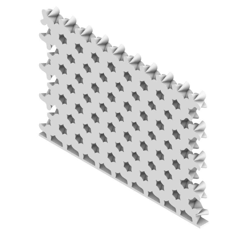
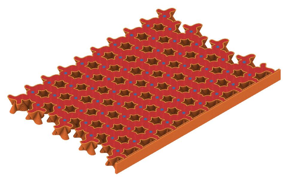
model is seen in figure 47. This final model printed well and was accurate to the elevation seen in figure 43.
45_
46_
DESCRIPTION
PARTITION WALL
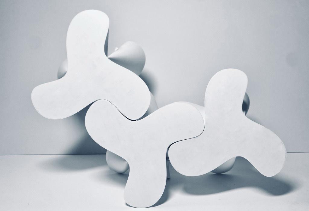
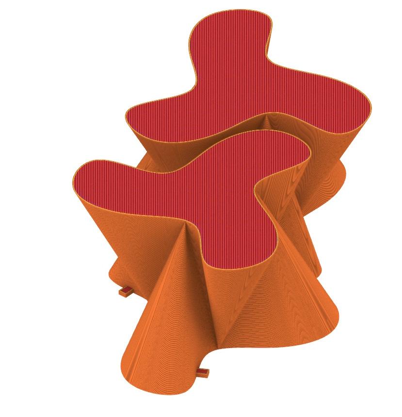
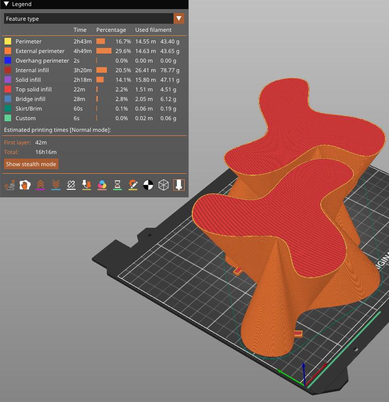
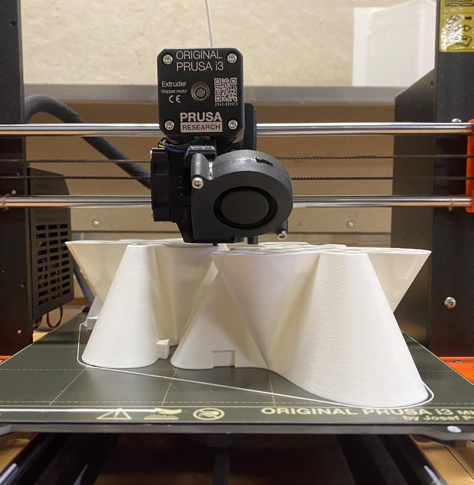
For the large scale 1:1 model each one of these pieces measures 4.3”x4,3”x4”. I added secondary interlocking pieces to reduce the degrees of freedom and help add to the stability of the model. During the printing process I encountered issues with the Prusa printing too fast and causing holes in the bottom layer. This was solved by reducing the printing speed down to 85%.
This solved the issue but increased the print time from over 16 hours to 19 hours. In total I printed three models to demonstrate how the interlocking model works. The final print interlocked well and generally worked.
50_
51_
