ADVANCED DIGITAL FABRICATION & PROCESS
FALL 2024



FALL 2024


DESCRIPTION
3D Model Making Process
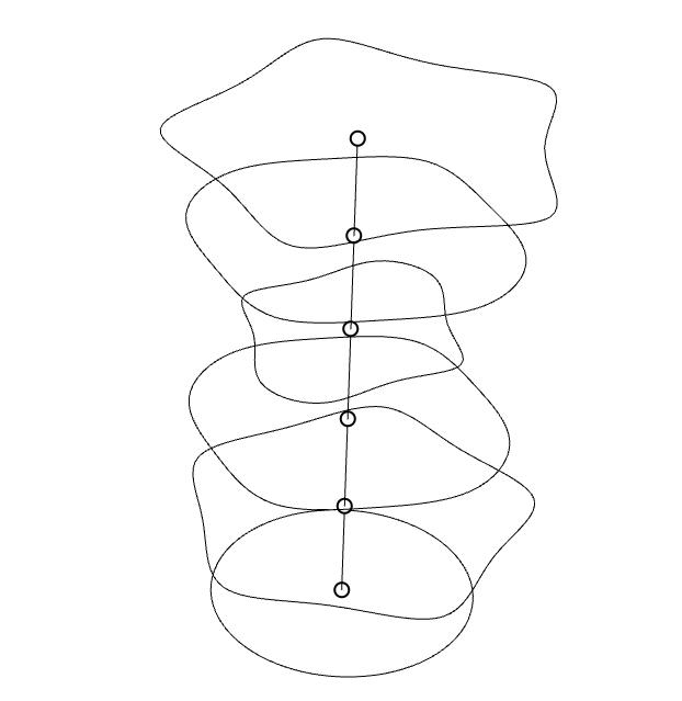
I created the first 3D model by making an elipe in Rhino7 and lofting it five times to create six total elipse stacked on one axes. I then pushed and pulled each of the elipse to create the desired contours of the vase which I then turned into a mesh. Once the object was a solid, I exported the file as a .stl and opened it in PrusaSlicer.
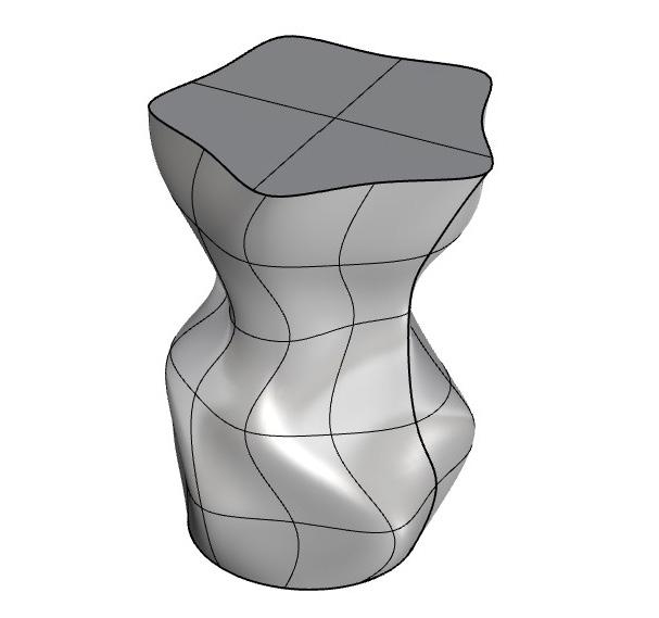
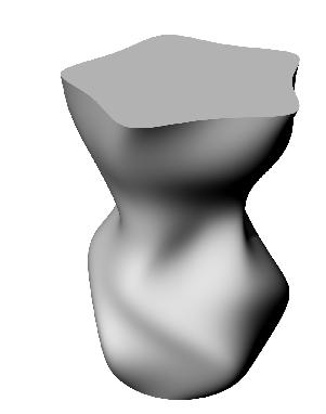
In PrusaSlicer and BamuSlicer I ensured that there was not too much of a twist in the contours of my vase that would cause a failure in the print process. I change the vertical shells to s[iral vase which tells the prnter to not use any infill. This I exported as G-code to print. 1_ 3D Rhino Model - Wireframe 2_ 3D Rhino Model - Mesh 3_ 3D Rhino Model - Render
4_ PrusaSlicer Preview
5_ 3D Print 6_3D Print -Error


6 shows some layer seperation that ocurred near the top of the vase where the contour was slightly too great. The resulting texture is thin and frail conpared to the rest of the print which was quite sturdy.


DESCRIPTION
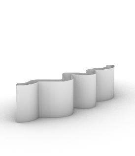
WALL WITH INFILL
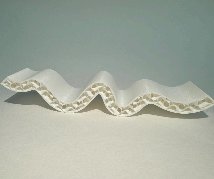
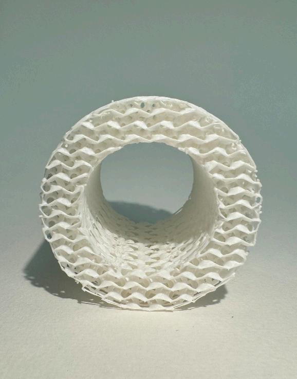
I created a curved wall in Rhino, then extruded it it to create a more solid for without capping it. In order to keep the infill visible. I used a 15% gyroid infill becuase it is curvy like my wall. For stability fo the print, I a few swipes from a glue still to the print bed as well as a raft in the model.
If I were to print this project again I would want to focus on the exterior wall which felt very bumpy. This was my first time printing independently so removing the model from the print bed was a new experience but it made me much more confident in handling projects on my own.

DESCRIPTION
REGIONAL SCALE
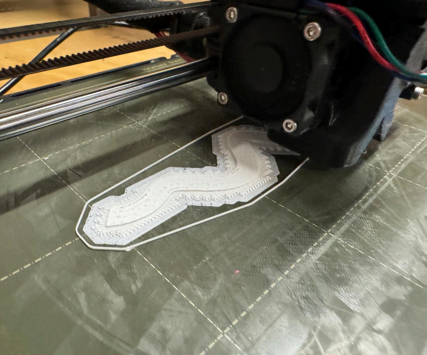
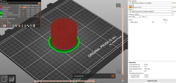
This model began with a cylander which I exported as a .stl file into PrusaSlicer where I removed the top solid layers and vertical shells (Fig. 2). By removing those layers, I was left with a 15% gyroid infill in the shape of my cylander. I made sure to use a raft to secure the object to the plate.
Post-print I realize my infill could have been a bit lighter as its density caused some issues with melting (see Fig. 3). Next time I would select a different infill pattern or lessen the the percentage of infill just to keep the object a bit more airy.
1_3D Rhino Model
2_3D Print Model
3_3D Print Side Closeup
4_PrusaSlicer Display
5_Prusa Print Raft
6_Prusa Print Early Progress
7_Prusa Print Late Progress


DESCRIPTION
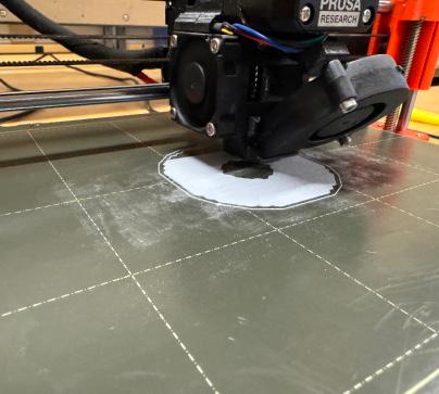
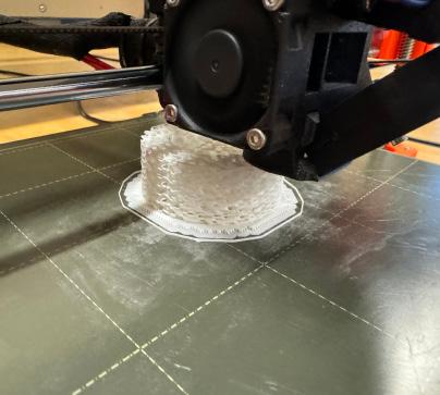
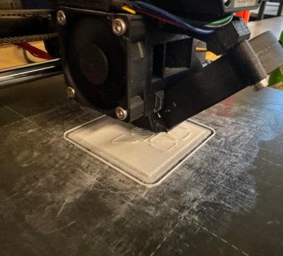
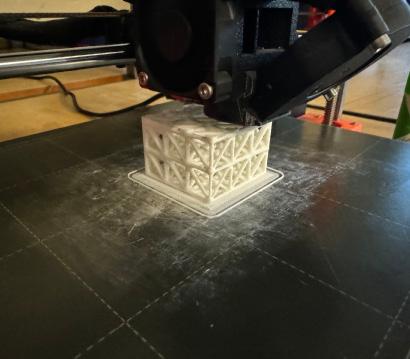
This 3D model began as a cube in Rhino that was then processed through grasshopper to create a series of lines with varying thickness based on a specific point. I then baked the grasshopper file and exported it as a .obj into PrusaSlicer. The print was wstimated to take fifteen hours which resulted in me scaling the model down within Prusa until the print took four hours.
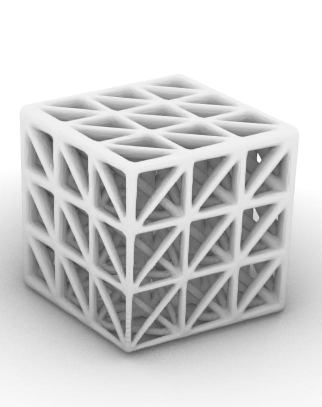
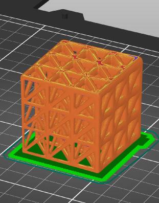
The next issue was that due to the contour of the base of my object, the print bed was only connecting on the tickest corner, so I was forced to cut off some of my design (see Fig. 5) which resulted in an interesting texture.
1_ 3D Rhino Model - Base
2_ 3D Rhino Model - Render
3_ PrusaSlicer Preview
4_ 3D Printed Model
5_3D Printed Model - Bottom Face
6_3D Printed Model - Melting
7_Prusa Print Raft
8_Prusa Print Early Stage
9_Prusa Print Late Stage

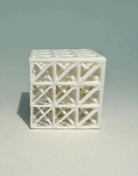
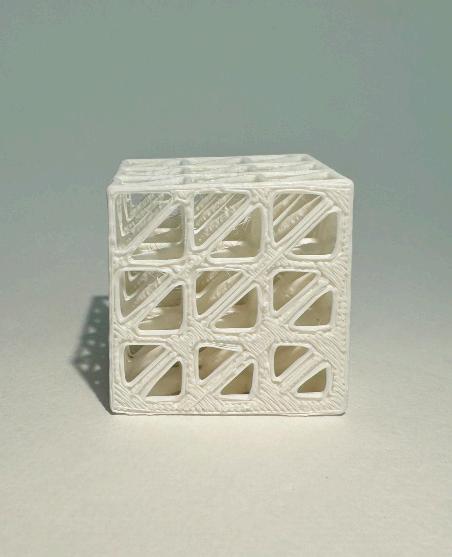
Fig. 4 and Fig. 6 show that if this model was printed at a larger scale, it may have been more neat. Many of the smaller connections were very bumpy and some areas had points of melting (Fig. 6). If I were to have another opportunity, I would try this at a larger scale to see if it might clean up the model.


DESCRIPTION
REGIONAL SCALE
This 3D model began as a polygon in Rhino that I seperated into three pieces by drawing three key shaped lines. One side I tested by doing a dovetail and one side I decided to make a key in order to test the tollerance at multiple angles.

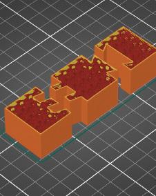
In order to ensure the pieces fit together accuratly, I facotred a tolerance of .3mm. I exported the model as a .stl and placed it in PrucaSlicer. I printed with a 15% gyroid infill for stability and did not need to use a raft or support material because the surface was flat.
2_
3_ PrusaSlicer Preview
4_ 3D Printed Model
5_3D Printed Model - Bottom Face
6_Prusa Print Raft
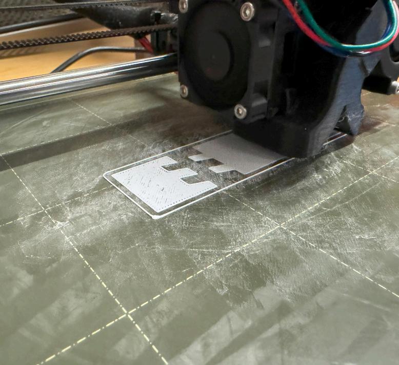
7_Prusa Print Early Stage
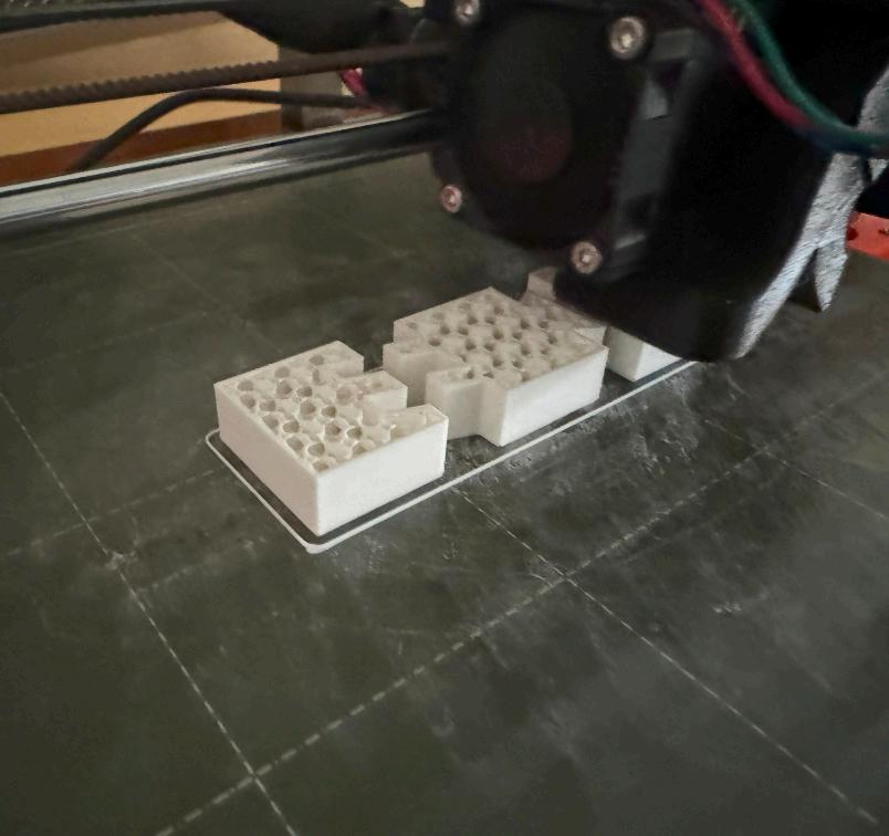
8_Prusa Print Late Stage

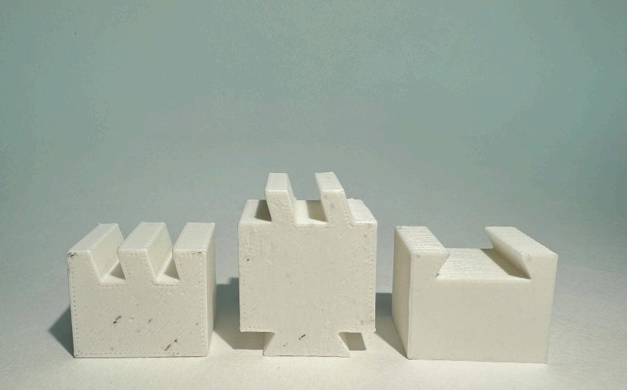
When printing, the dovetail end fit perfectly, but the key end was so tight I had to srike it with a metal waterbottle. With sanding, the key side does fit. Due to melting, the pieces were too snug and gaps were formed as shown in Fig. 4.

DESCRIPTION
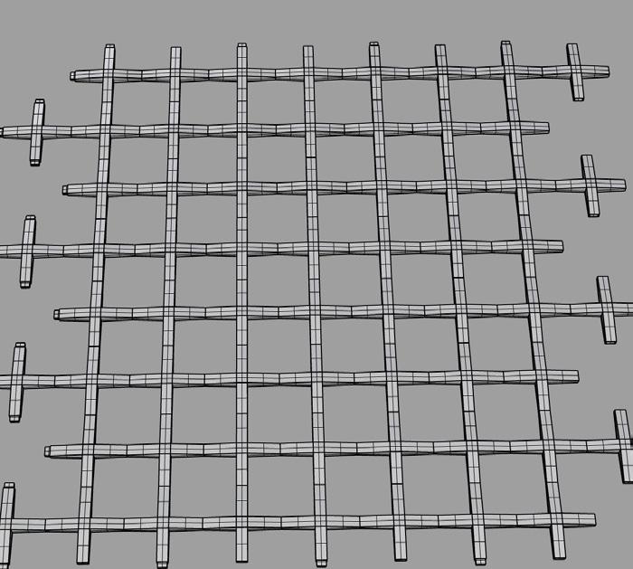
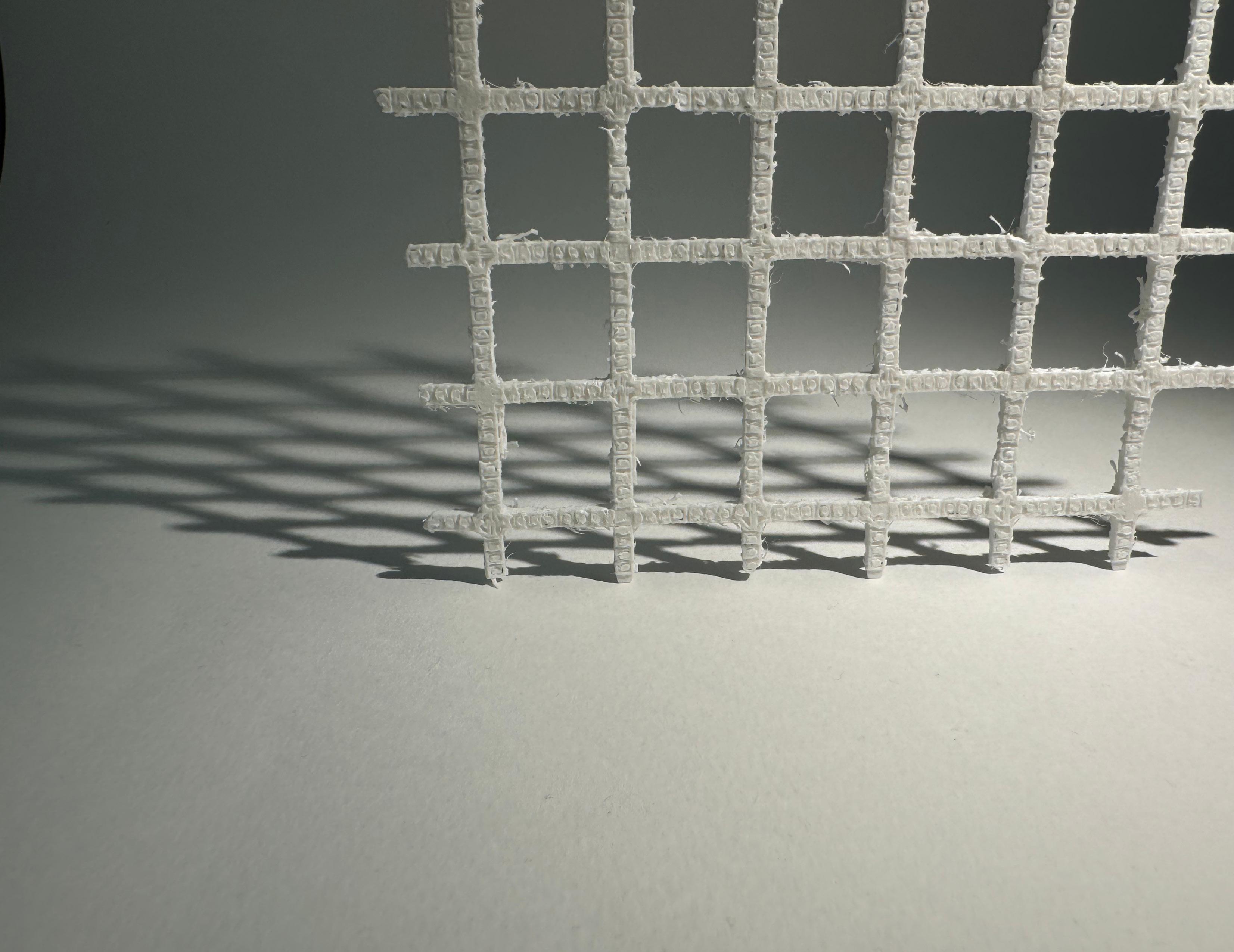
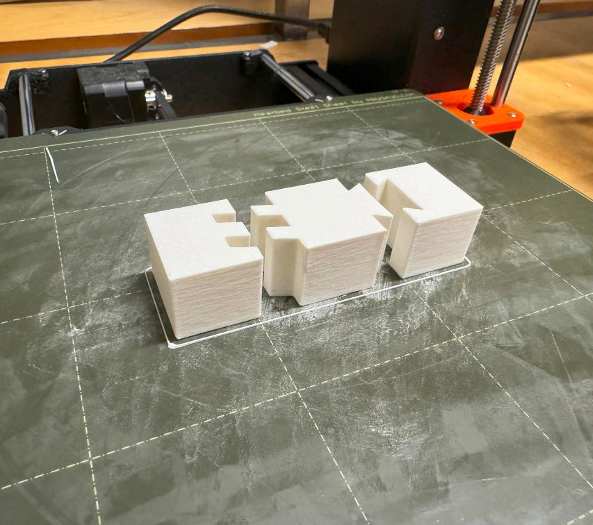
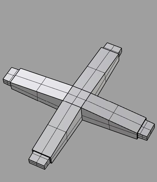
This model is a system of crosses that lock to gether with a male-female connection to create a woven pattern that will be back-lit in my building for studio. The idea is to create a stitching pattern that makes the building appear that it is stitched together.
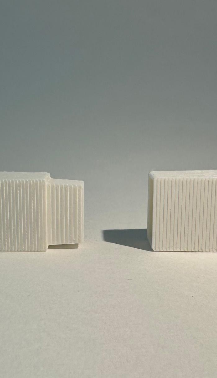
I started by creating male and female pieces that I then cut to test print the connection alone. The first print I tried had a tolerence of .03 which fit snug, however, I experimented with tapering the joint which made it too loose (Fig. 3). Once the tolerence was correct, I printed the entire piece (Fig. 5).
1_ 3D Rhino Model - Base
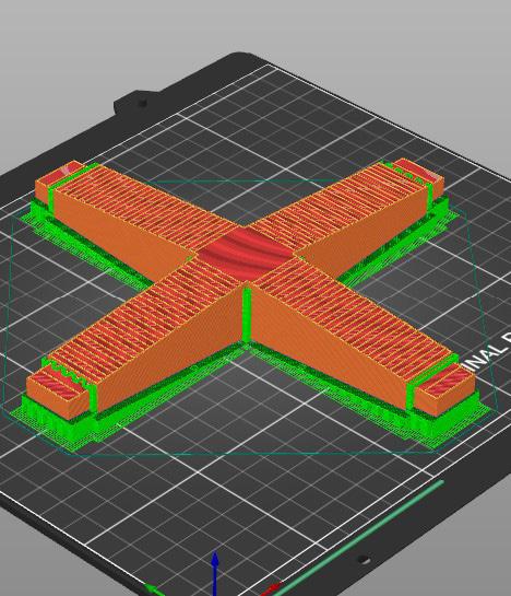
2_ PrusaSlicer Preview
3_ 3D Printed Connection Test
4_ 3D Printed Connection Fit
5_3D Printed Full Model Connection
6_ 3D Rhino Scale Model
7_ PrusaSlicer Scale Model Preview
8_ 3D Printed

I printed the pieces at full scale and at 1 1/2 inch architectural scale. The full scale was printed with automatically generatwed supports in PrucaSlicer which performed well. The 1 1/2 in scale model was very flimsy and hard to clean up. In the future I would prefer to use a smaller nozel for preceision or a much larger architectural scale.
