Module 1
Vase, Infill, & Gradient
VASE DESCRIPTION
MODELING AND PRINTING A VASE
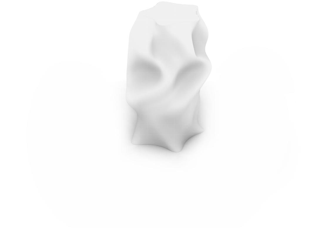
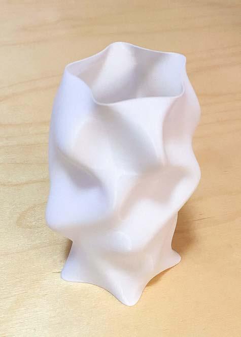
To create a vase 3D print we started with a simple circle shape in rhino and copied it up along a line at equal intervals to create a six circles total. We then manipulated each of the circles independently by adding points to the circle and pushing and pulling them. The circles were also rotated to create more changes. We then used the loft command and selected all of our created curves in
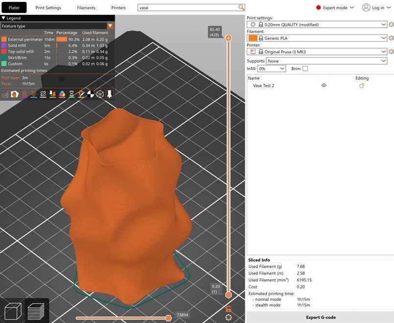
order to create a surface for the model. Once the surface was created we were able to continue to manipulate the different circles to further alter the design. To complete the model we caped the surface and exported that surface as an STL file for Prusa 3D printer. Next we opened the file in Prusa and typed into the search line vase and clicked on spiral vase. By following Prusa’s
setting recommendations we were able to set up the file to 3D print a vase. Next we sliced the file by clicking on the layered cube on the bottom right and check to make sure there weren’t any layer gaps in the slices. One of the feet of my file had a slightly too severe of an angle, the printing went well, but the vase does not hold water.
Top Face
3D Model, wireframe
3D Model, wireframe with surface
3D Model, rendered surface
FIGURE
FIGURE
FIGURE
Import STL/OBJ into Prusa and slice using the spiral vase settings. Make sure to check the layers to see if there is any separation between them that will cause gaps in the printing. The layers on this vase at the base are at an angle that is too severe and has slight gaps in the print that allow water to leak through.
Use vase printing settings
Angle of print too severe
INFILL WALL DESCRIPTION
MODELING AND PRINTING A WALL WITH INFILL
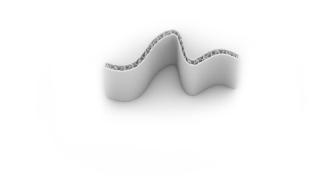
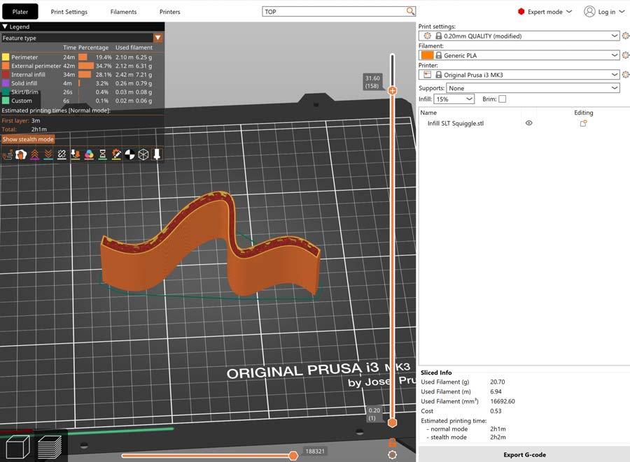
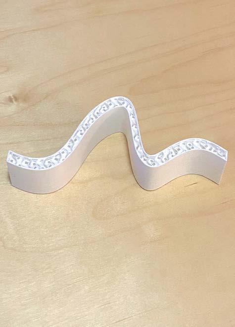
For this 3D model Rhino was used to create a curved figure that was extruded up to create a wall. The extrusion was exported as an OBJ file and opened in Prusa. In the Prusa file a 15% gyro infill was applied to the model to give it more structure. Make sure to check if the infill is dense enough to touch both sides of the wall when printing. A OBJ file was exported out of Prusa and
and opened again in Rhino to create the 3D model in figure 3. The top layers were left off of the print in order to see the infill of the wall. This print was success, 15% infill was sufficient to create a sturdy wall.
Exposed infill
FIGURE
FIGURE 2
FIGURE
The structure of the wall could probably be achieved with a smaller infill percentage. 10% was the lowest with this pattern that the infill would touch both sides of the wall exterior.
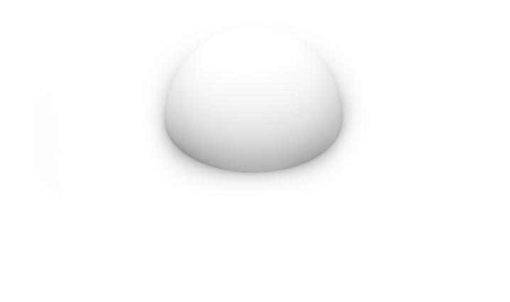
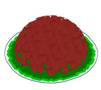
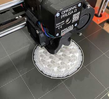
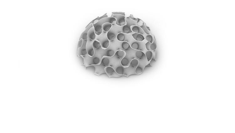
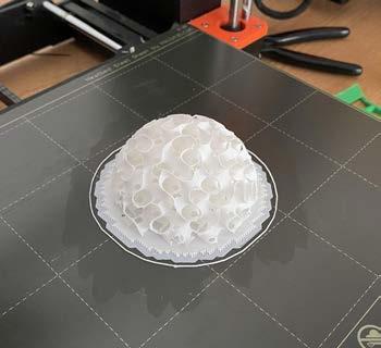
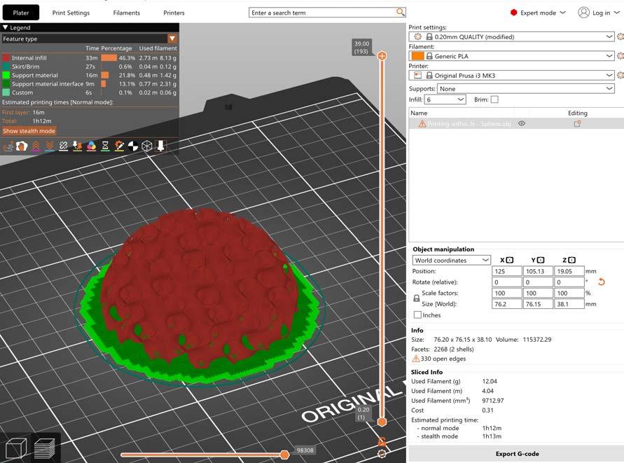
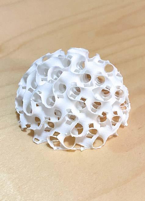
For this infill without walls print a half sphere was used. First the half sphere was created in Rhino and then it was exported as an OBJ to Prusa. Prusa was used to slice the half sphere and the walls of the print were removed to leave only the 6% gyro infill. Make sure to consider the infill percentage carefully, for this print anything below 6% caused major structural problems.
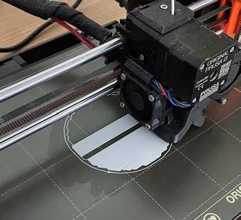
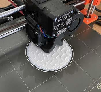
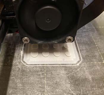
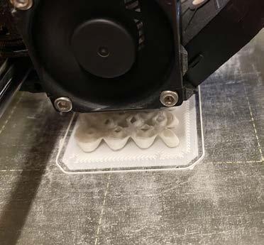
Figures 5-8 show the printing process from the brim and skirt printing in figures 5 and 6 to the completed 3D model in figure 8. The main difficulty with this model was removing the final print from the skirt after the print was done without damaging its base.
1_ 3D Model, original rhino shape
2_ 3D Model, original rhino rendered
3_ 3D Model, import into Prusa
4_ 3D Model, Rhino from Prusa
5_ Print, laying down a base
6_ Print, gyro infill start
7_ Print, in process infill
8_ Print, completed print
3”
FIGURE 1
FIGURE 5
FIGURE 2
FIGURE 6
FIGURE 3
FIGURE 7
FIGURE 4
FIGURE 8
Infill less than 6 is hard to print
Missing part of gyro pattern
Removing from skirt was difficult
Final printed model has gaps in the gyro pattern due to layer thickness. The printer layers made it miss a square of the gyro pattern throughout the print, but the structure is still strong.
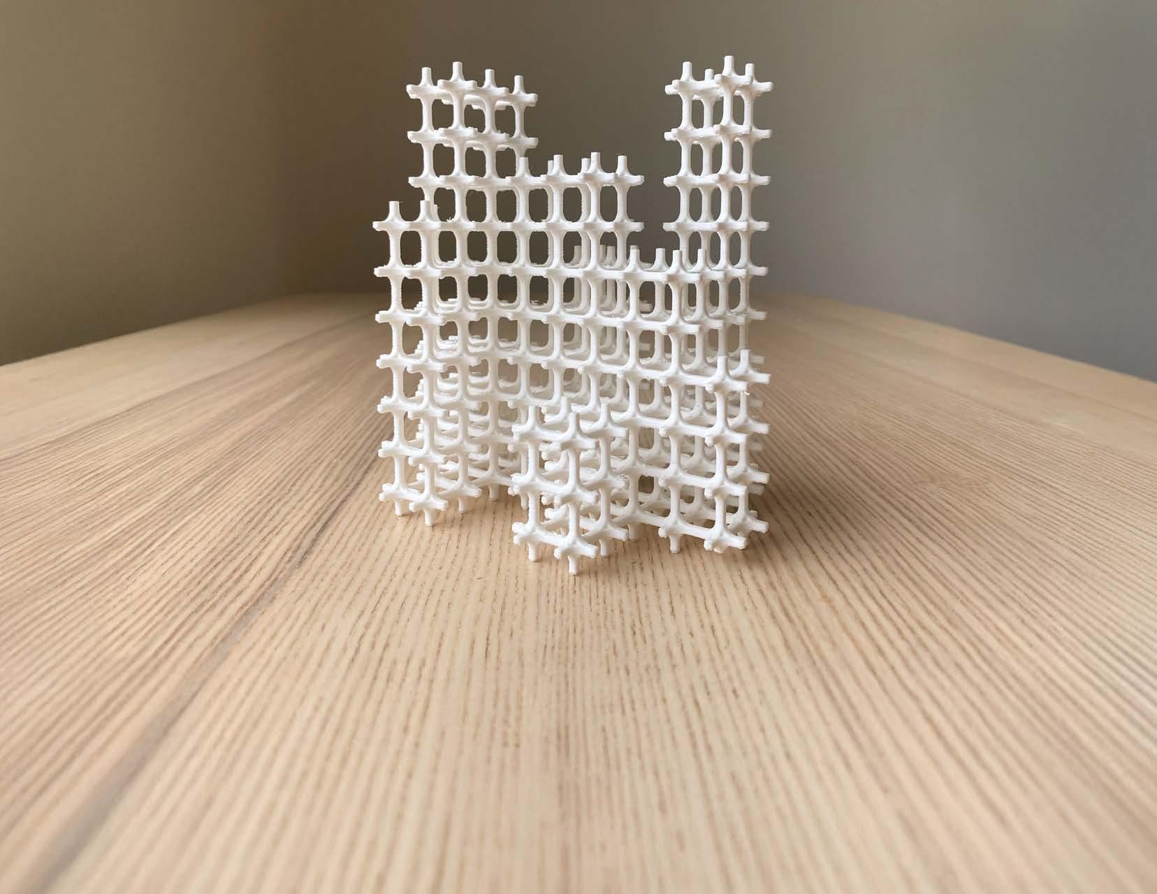
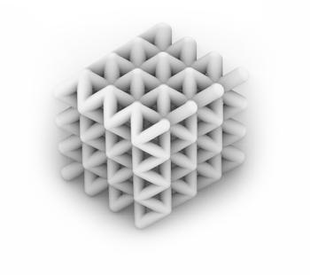
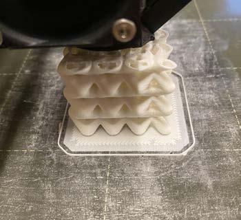
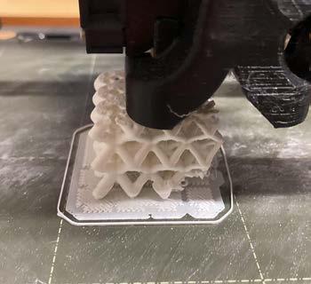
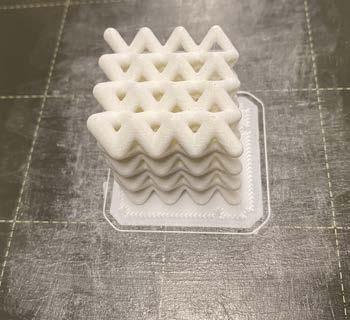
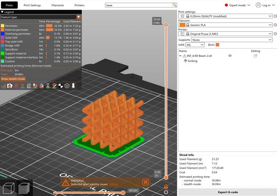
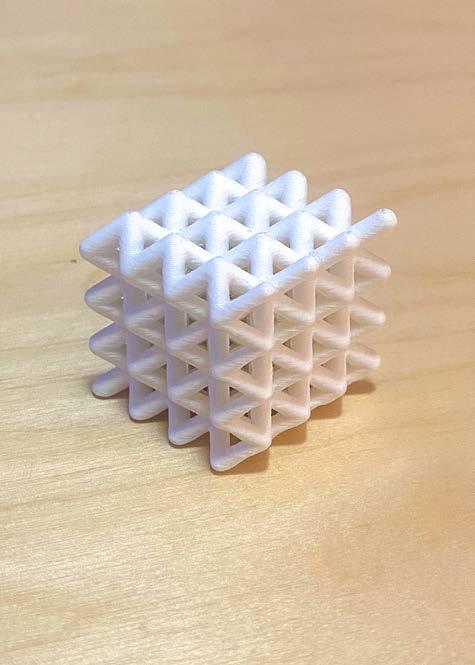
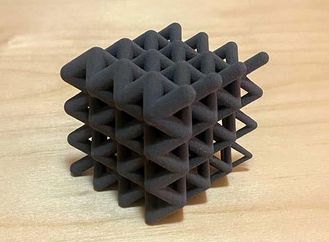
For this print a script in grasshopper was used to create a box structure formed from lines. These lines were given a thickness using the grasshopper script, which was visualized in Rhino (figure 3). This frame was then backed in grasshopper to create a mesh version in Rhino that was then exported as an OBJ file. The OBJ file was then opened in Prusa and
sliced in Prusa. The first iteration of this model failed because the frame on the thin end was too skinny to support the model (figure 4). The model was then adjusted to increase the thickness of the frame and the next print worked well.
The biggest issues with this printing process were the thickness of the frame and making sure to eliminate the infill of the 3D print because of the time it adds to the overall printing process.
1_ 3D Model, lines from grasshopper
2_ 3D Model, grasshopper cube
3_ 3D Model, rhino rendered
4_ Print, first failed print
5_ Print, laying down a base
6_ Print, building up layers
7_ Print, in process printing
8_ Print, completed print
Model too thin
FIGURE 1
FIGURE 5
FIGURE 2
FIGURE 6
FIGURE 3
FIGURE 7
FIGURE 4
FIGURE 8
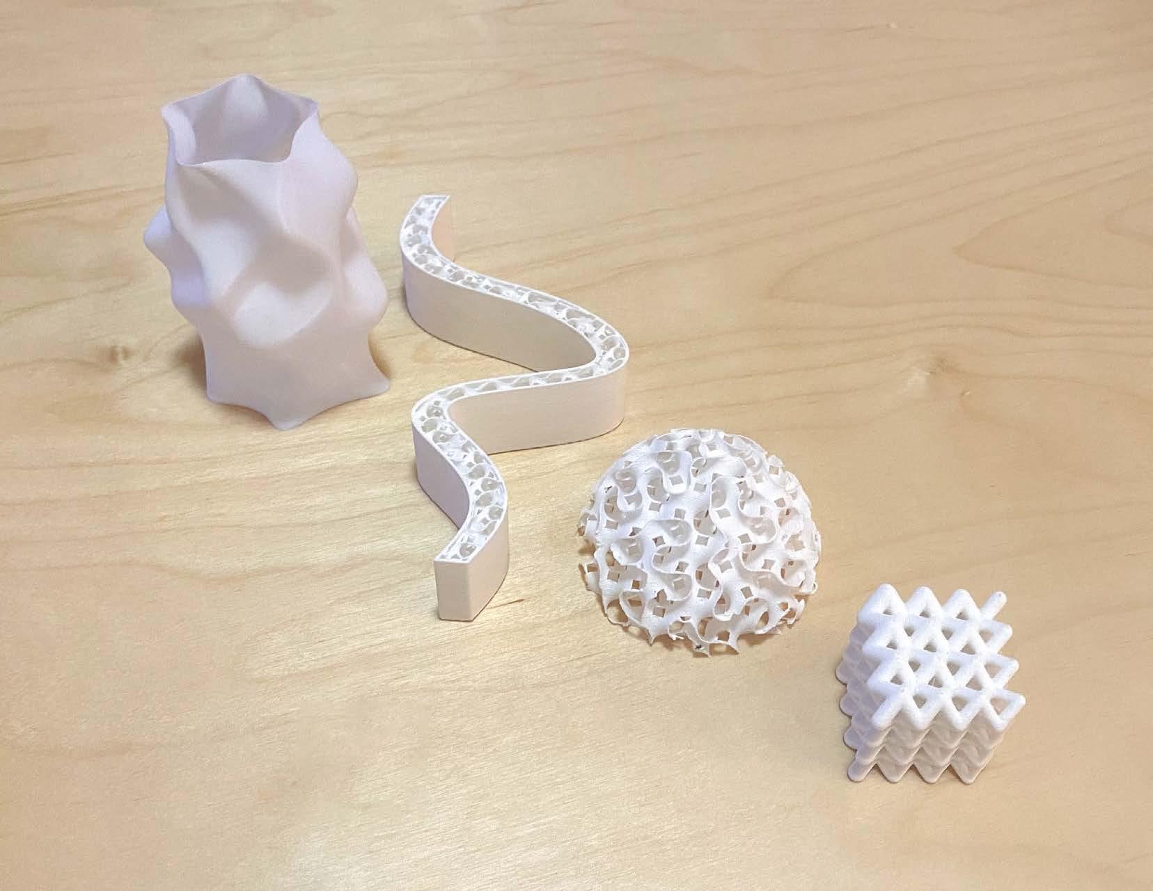
The first failure of the project occurred after the file was scaled down in Prusa. Make sure to check member thicknesses after scaling down a file to make sure that the print will still be viable. The white print is done on the Prusa 3D printer and the dark print is done with the powder 3D printer. The powder printing is more accurate and doesn’t need supports.
Module 2
3D Printed Assemblies
TOLERANCE TESTING
PROCESS AND METHOD
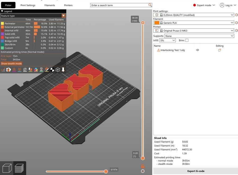
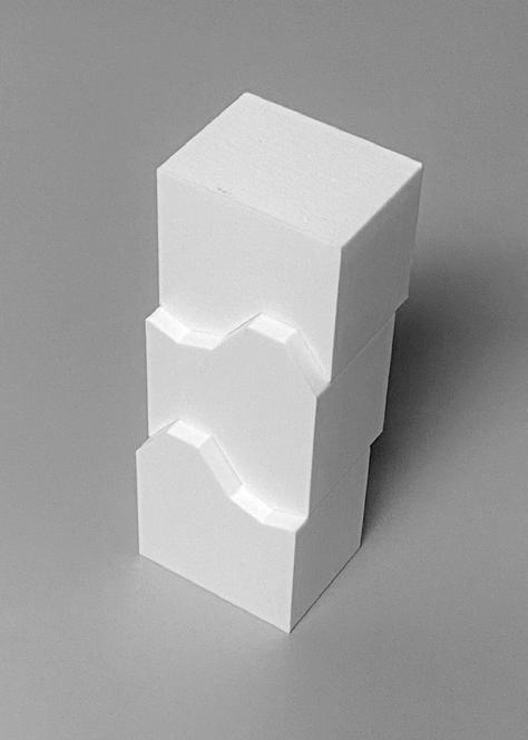
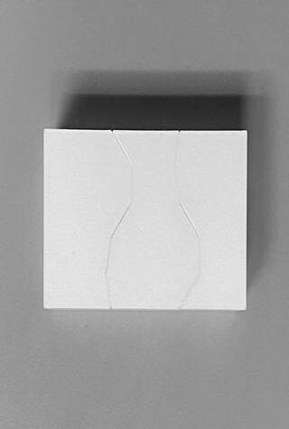
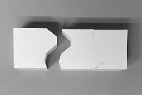
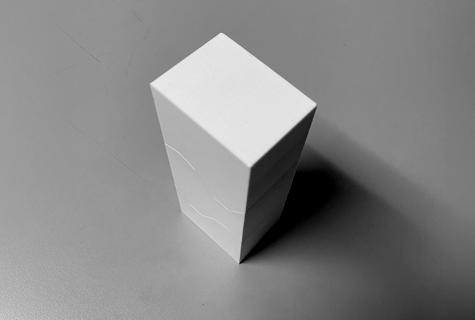
For this model a simple shape was created in Rhino with interlocking edges. This was to test the tolerance of the printer when connecting different shapes together. The .15mm tolerance worked well and the shapes fit together tightly.
3D Model, wireframe
3D Model, wireframe with surface
FIGURE 1
FIGURE 2
FIGURE 3
.15mm offset
INITIAL DESIGN
PROCESS AND METHOD
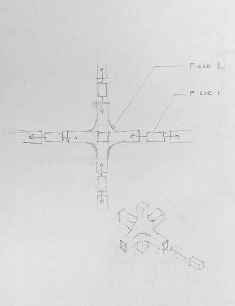
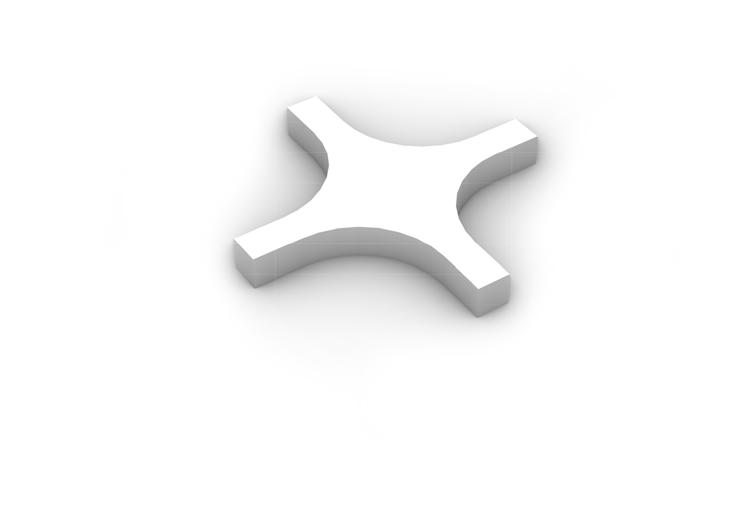
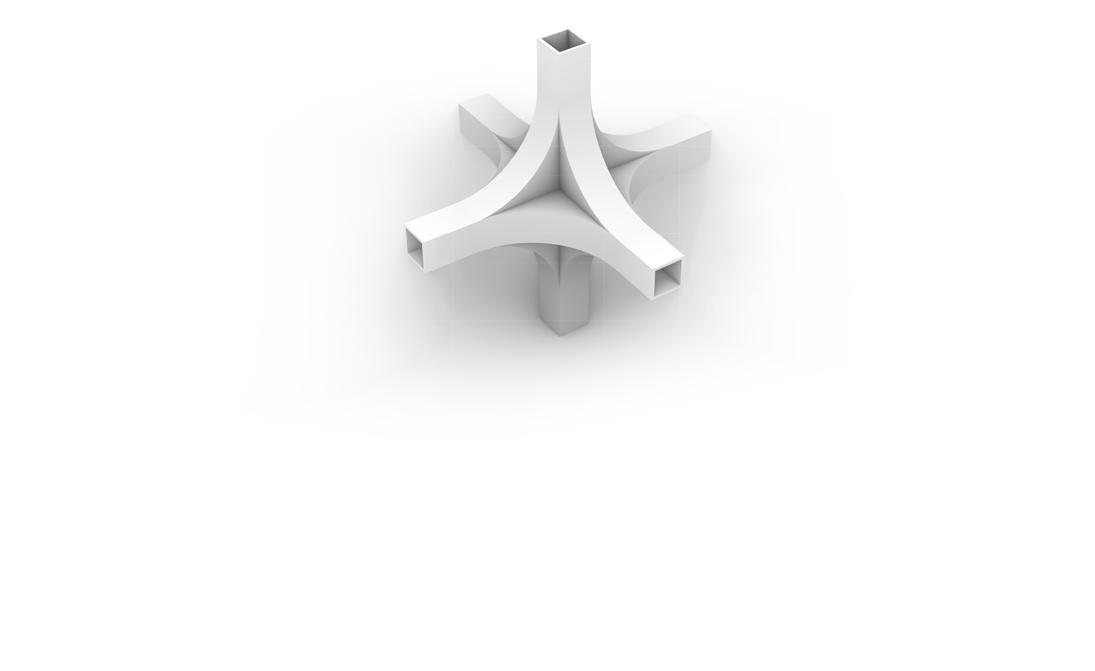
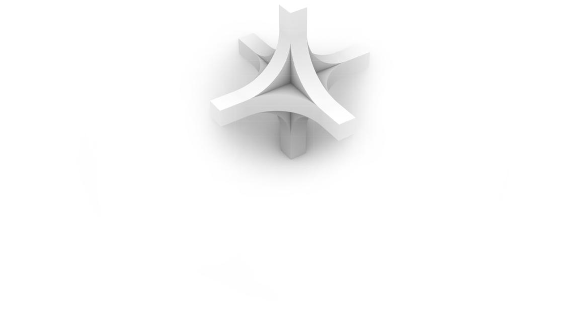
Initial design concept starting with a simple sketch that showcases two pieces, the primary piece with six connection points and the secondary connector that holds the primary pieces together. The connector pieces have a .15mm offset from the interior of the primary piece in order to create a tight fit. The walls of the primary piece at the connection areas are
1/16” thick, which is strong enough to handle the pressure of inputting the connector. The connectors can be varied in length in order to create a large array. It was important to test a variety of offsets for the connector in order to achieve the perfect fit. For this project I tested .1mm, .15mm, .3mm, and .4mm with .15mm working the best.
Sketch, initial idea
3D Model, first phase
3D Model, overall shape
FIGURE 1
FIGURE 2
FIGURE 3
Figure 5 shows how the array can be expanded in the XYZ directions and can be repeated as many times as needed to create the desired final structure.
Connector w/ .15mm offset
5_ 3D Model, array
4_ 3D Model, shape with connection
FIGURE 4
FIGURE 5
50% SCALE PRINT PROCESS AND METHOD
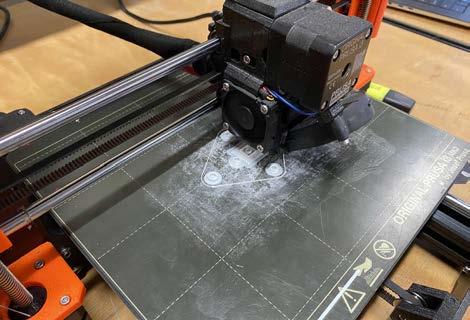
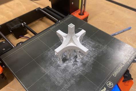
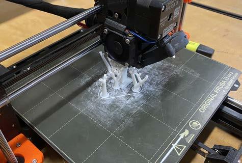
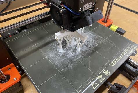
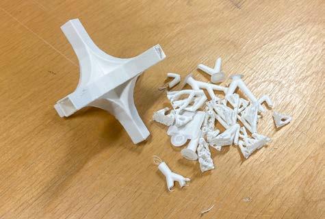
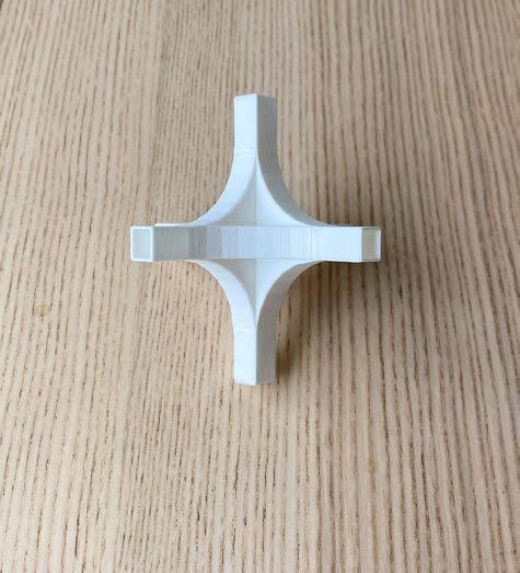
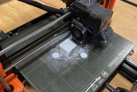
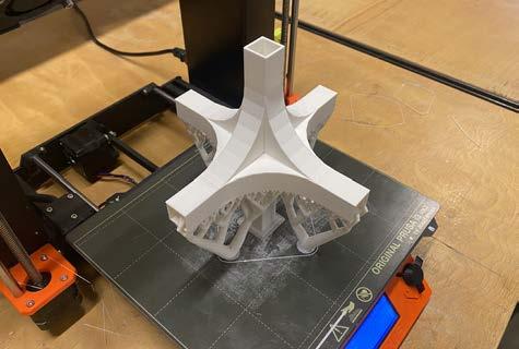
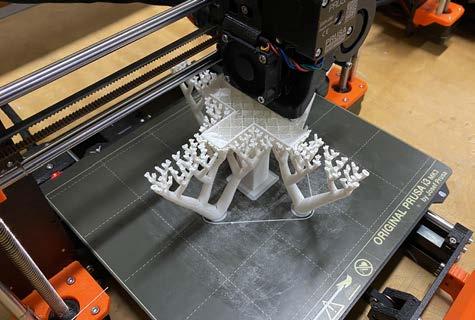
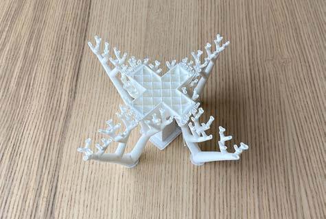
Here are the process steps for creating a 50% scale print of the primary component of the array. Organic supports were applied to support the cantilever and at this scale they worked very well. They were also easy to remove from the exterior, but very difficult to remove from the connection areas because they were too small to get a tool inside. It’s very important to watch
the model build organic supports to make sure they get established, because they can easily fall over and ruin the print.
1_ Print, laying down the base
2_ Print, organic supports and early print
3_ Print, supports complete
4_ Print, model complete
5_ Print, supports removed
6_ Print, final 50% model
FIGURE 4
FIGURE 5
FIGURE 6
FIGURE 1
FIGURE 2
FIGURE 3
100% SCALE PRINT
PROCESS AND METHOD
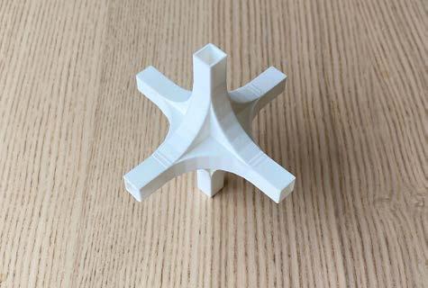
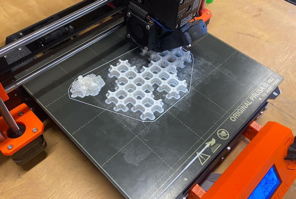
Here are the process steps for creating a 100% scale print of the primary component of the array. Organic supports were applied to support the cantilever and at this scale they worked very well on two of the three printers used. On one printer the organic supports fell over during the print (figure 5). This was caught early and the print was canceled, for a model of this size
using the grid support would probably be more effective, but less efficient than the organic supports.
1_ Print, laying down the base
2_ Print, organic supports and early print
3_ Print, supports complete
4_ Print, model complete
5_ Print, failed print showing supports
6_ Print, final single element
FIGURE 4
FIGURE 5
FIGURE 6
FIGURE 1
FIGURE 2
FIGURE 3
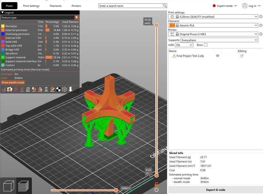
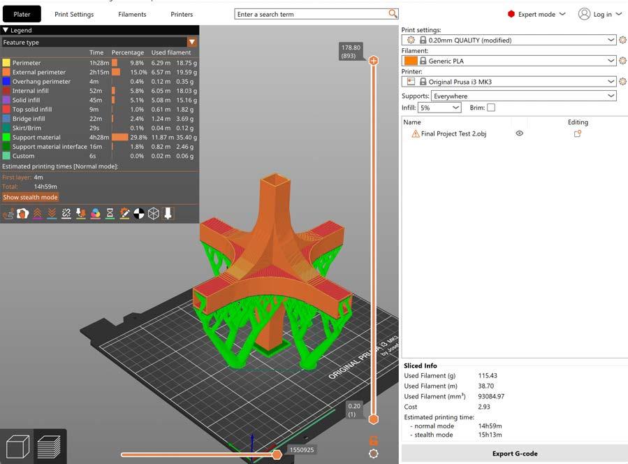
The print time for this model was very time consuming, this was mostly due to the scale and the use of supports. The image above shows that creating the support material accounted for 29.8% of the print time.
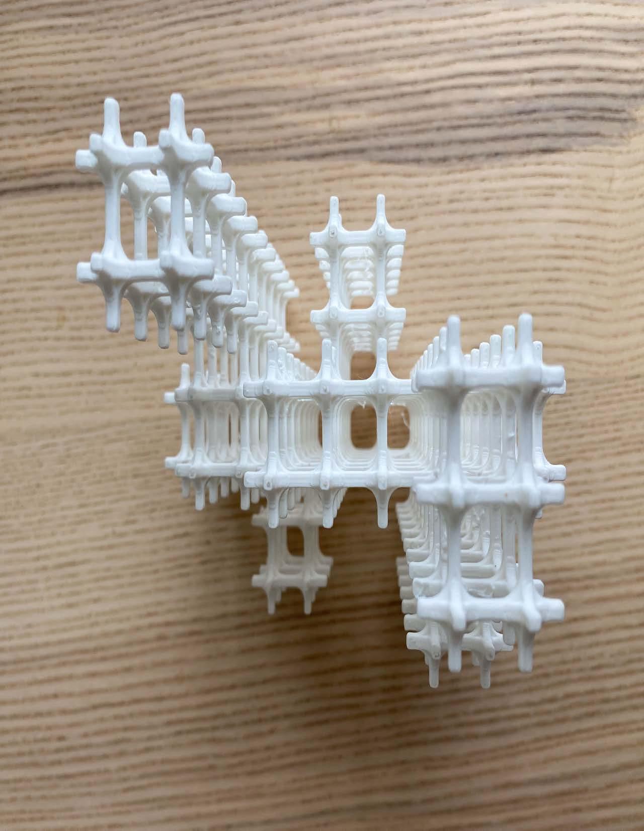
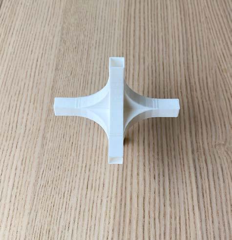
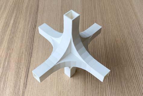
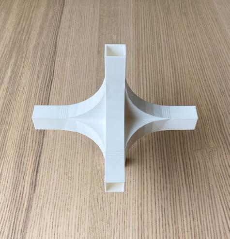
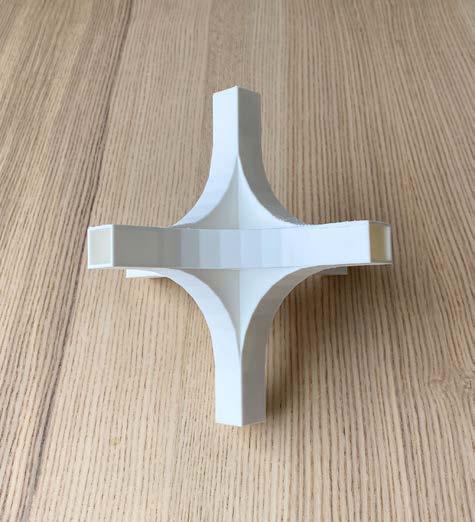
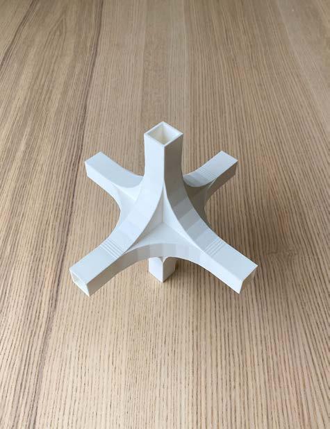
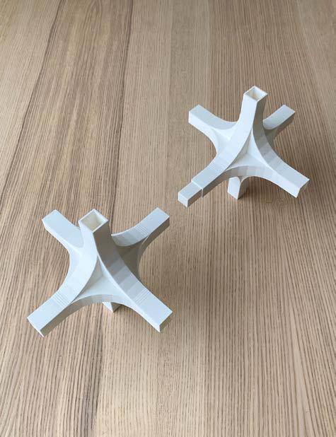
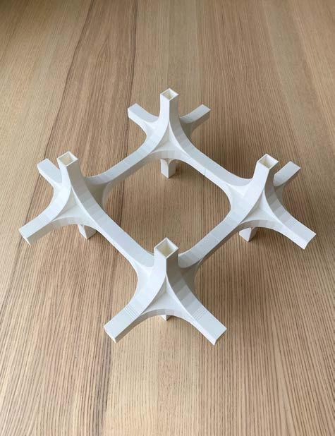
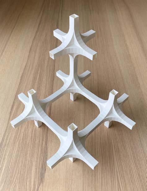
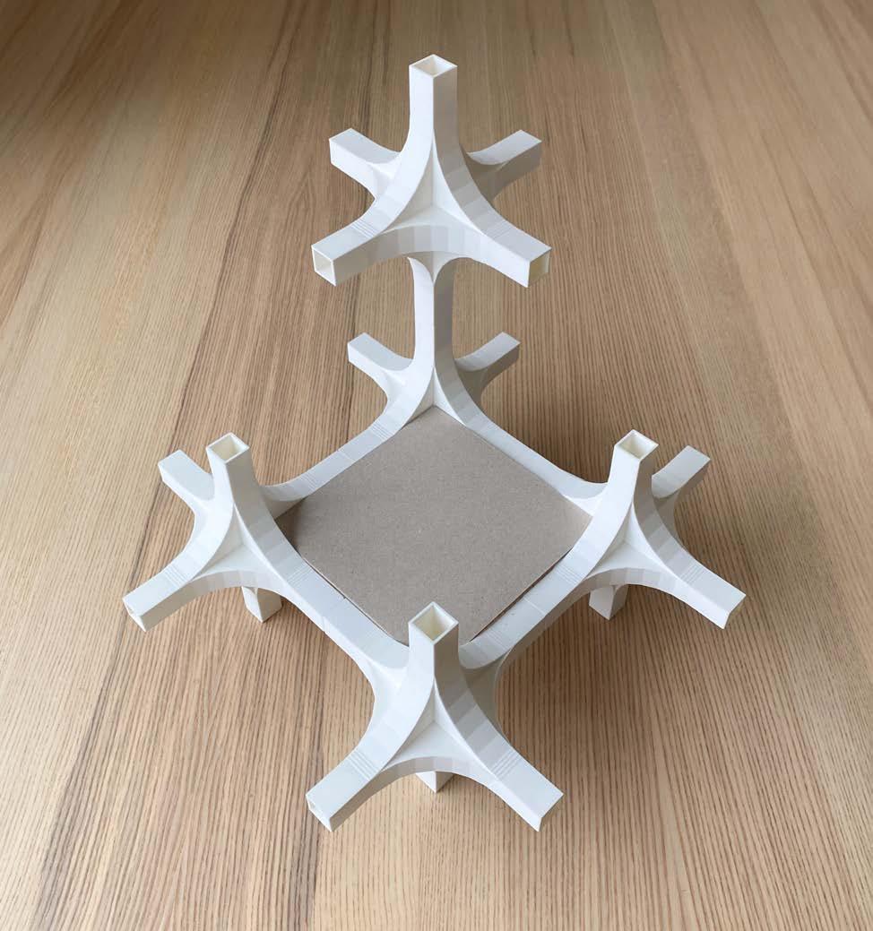
Here are the final models printed at full scale. The figures show how the pieces can be arrayed and expanded in order to create a shelf system. It’s important to lightly sand the connector pieces to make sure there aren’t any bumps or slight defects that can damage the connection point. Figure 5 shows how shelves can be created by adding a flat material to the middle
square created by connecting four of the primary pieces. Overall the printing process went well for this portion of the project other than the organic supports falling down during one of the prints.
1_ Print, one full scale module
Print, connection between elements
Print, one arrayed unit
FIGURE 1
FIGURE 2
FIGURE 3
4_ Print, array in the XYZ
5_ Print, model with shelf example
FIGURE 4
FIGURE 5
FINAL ARCHITECTURAL SCALE
ARCHITECTURAL
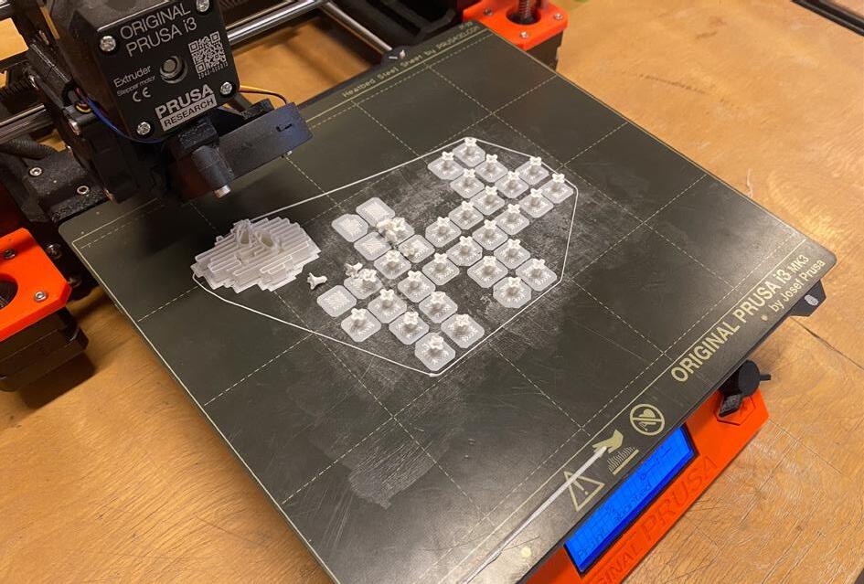
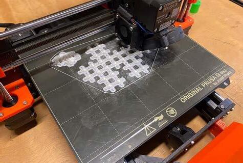
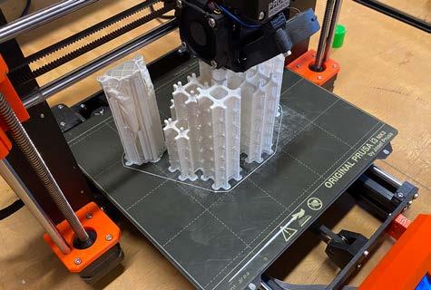
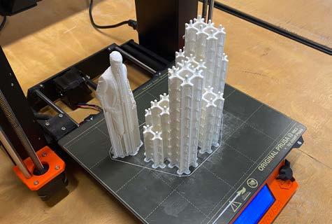
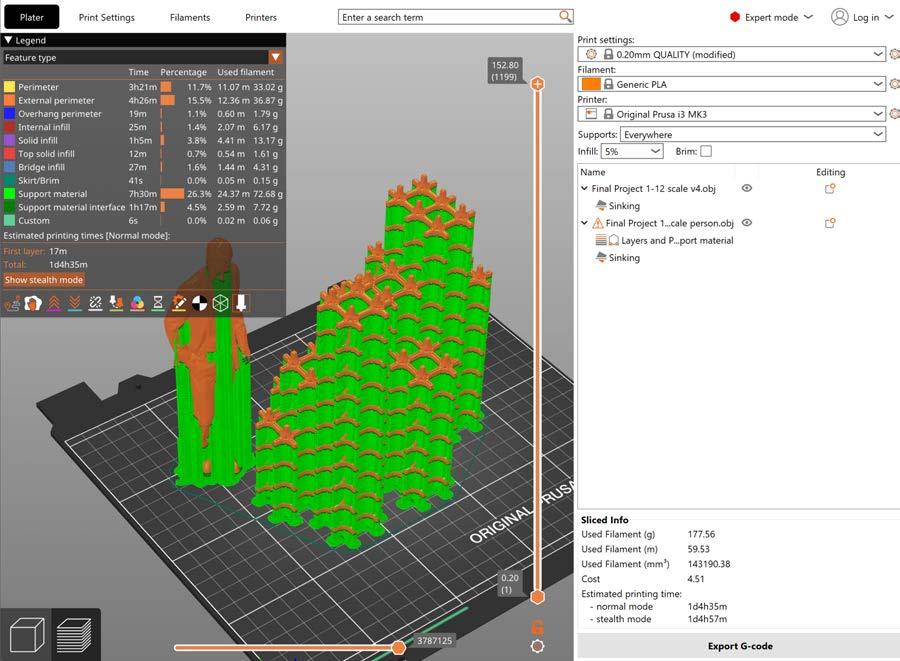
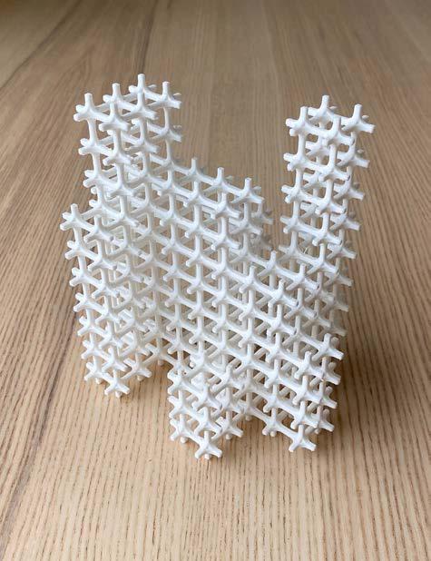
Here is the process of printing a scale model of the entire shelf structure. The model was built in Rhino and exported to Prusa. The size of the pieces was too small for Prusa to print so in Rhino 8 a shrinkwrap was applied to give the model an offset of .1mm and this made it thick enough to 3D print. The shrinkwrap took a lot of computer power on a complicated
model like this so make sure to have the computer plugged in. The first print was attempted without supports in order to save time, but it failed after one hour. Snug supports were applied and the print worked very well although it was almost 30 hours long.
1_ Print, failure no supports
2_ Print, laying down the base
3_ Print, rect. supports and early print
4_ Print, model process w/ supports
5_ Print, model complete
6_ Print, supports removed
FIGURE 4
FIGURE 5
FIGURE 6
FIGURE 1
FIGURE 2
FIGURE 3
6’
FINAL ARCHITECTURAL SCALE
ARCHITECTURAL SCALE ASSEMBLY
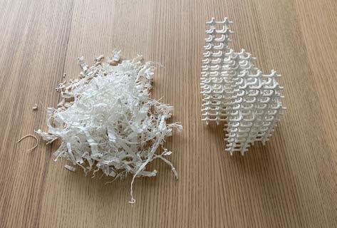
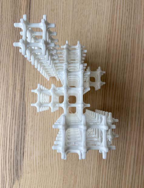
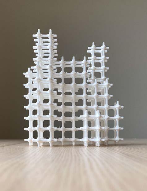
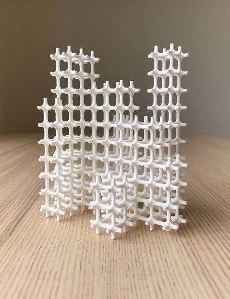
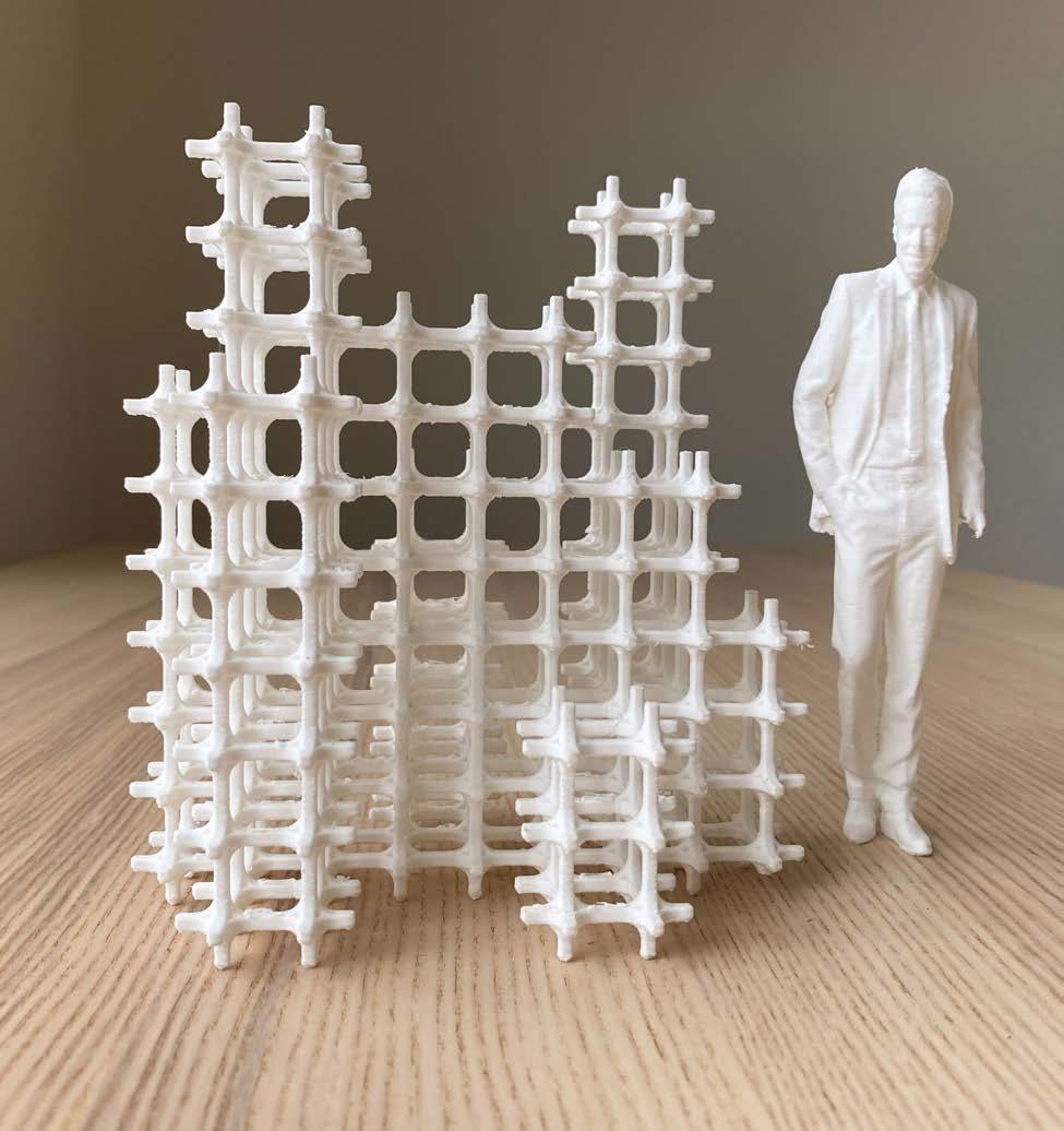
Here are the final photos of the architectural scale model. Removing the supports from this was very difficult, but the model turned out great and all of the cantilevers were successfully printed. This architectural scale model showcases one potential way to arrange the array to create shelving. Other opportunities with this design would be to increase the connectors
length in order to make the spacing of the shelves larger.
FIGURE 1
FIGURE 2
FIGURE 3
4_ Print, final scale model
5_ Print, final scale model with scale figure
FIGURE 4
FIGURE 5
