ADVANCED DIGITAL FABRICATION

VASE, INFILL & GRADIENTS 2
3D PRINTED ASSEMBLIES


DESCRIPTION

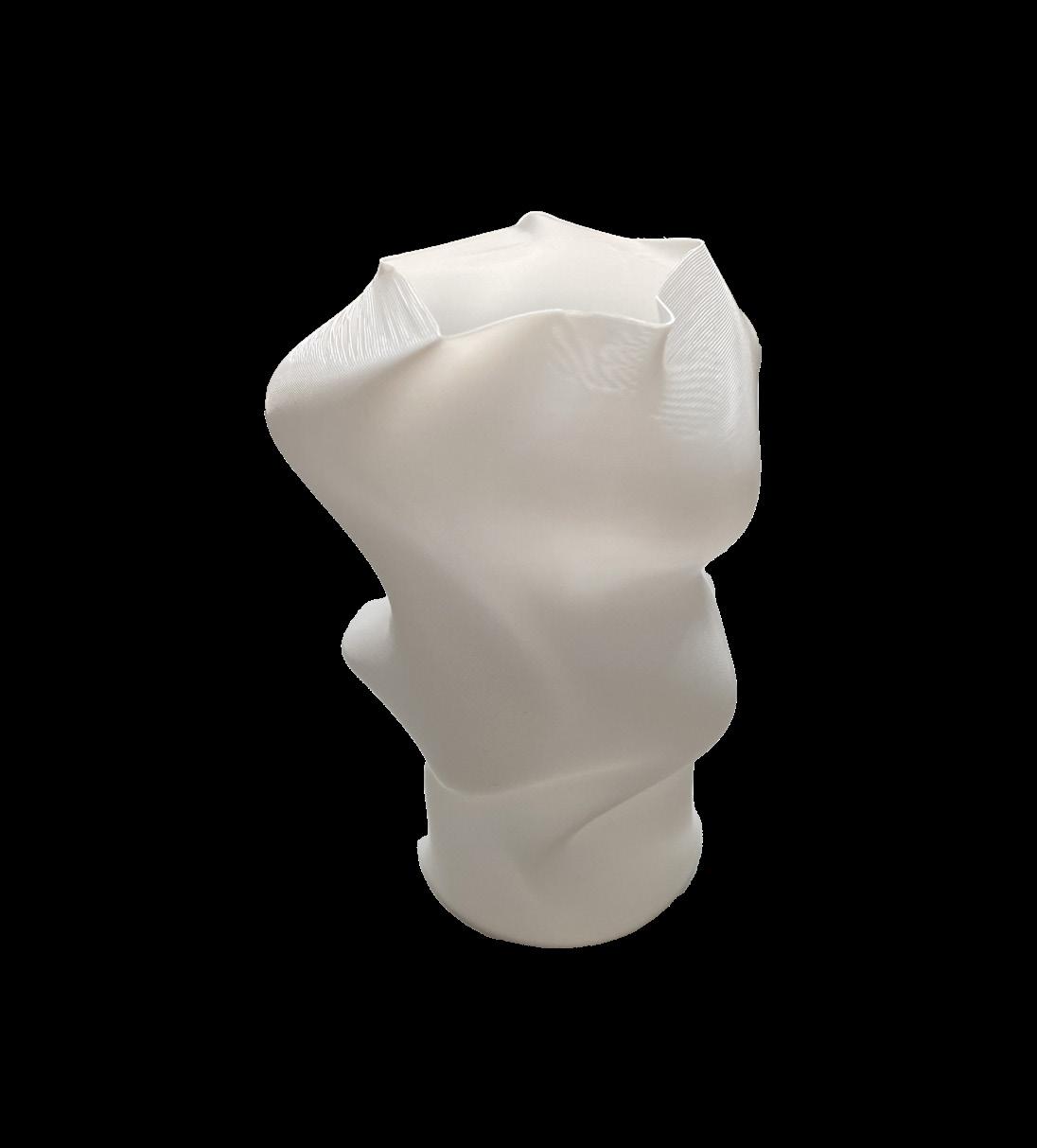
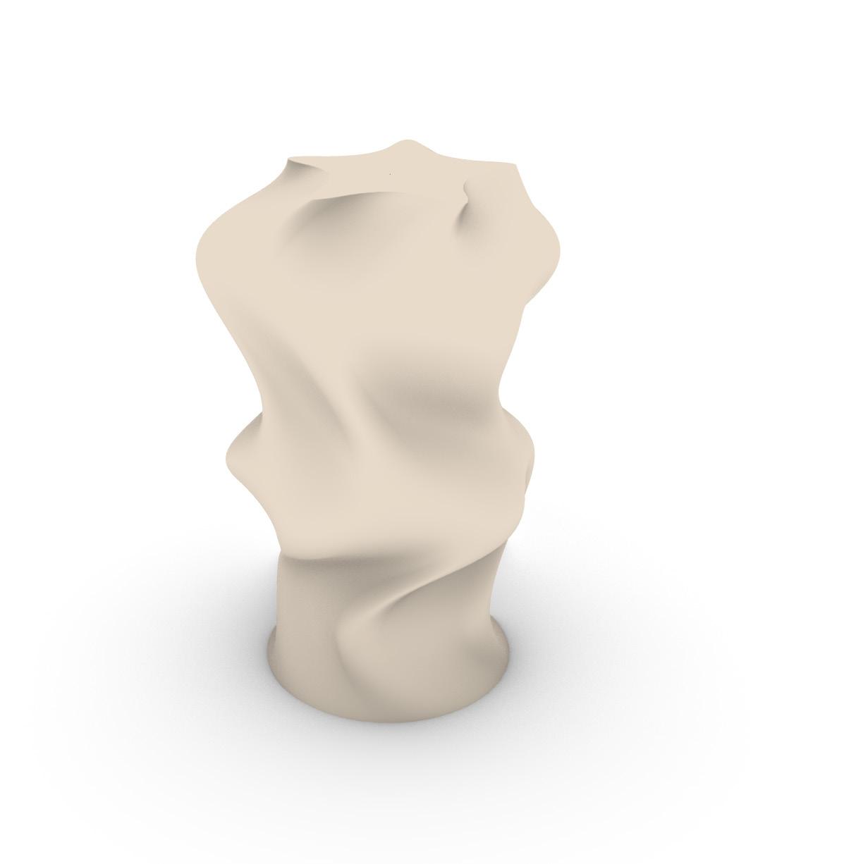
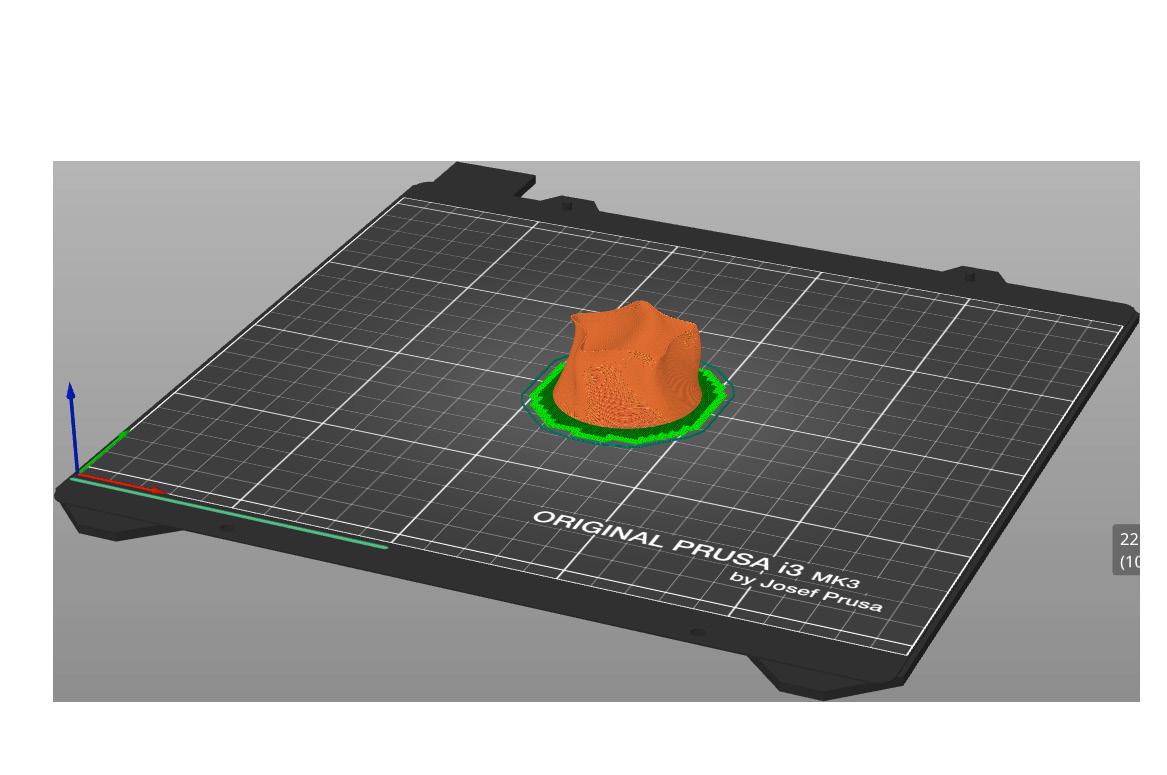
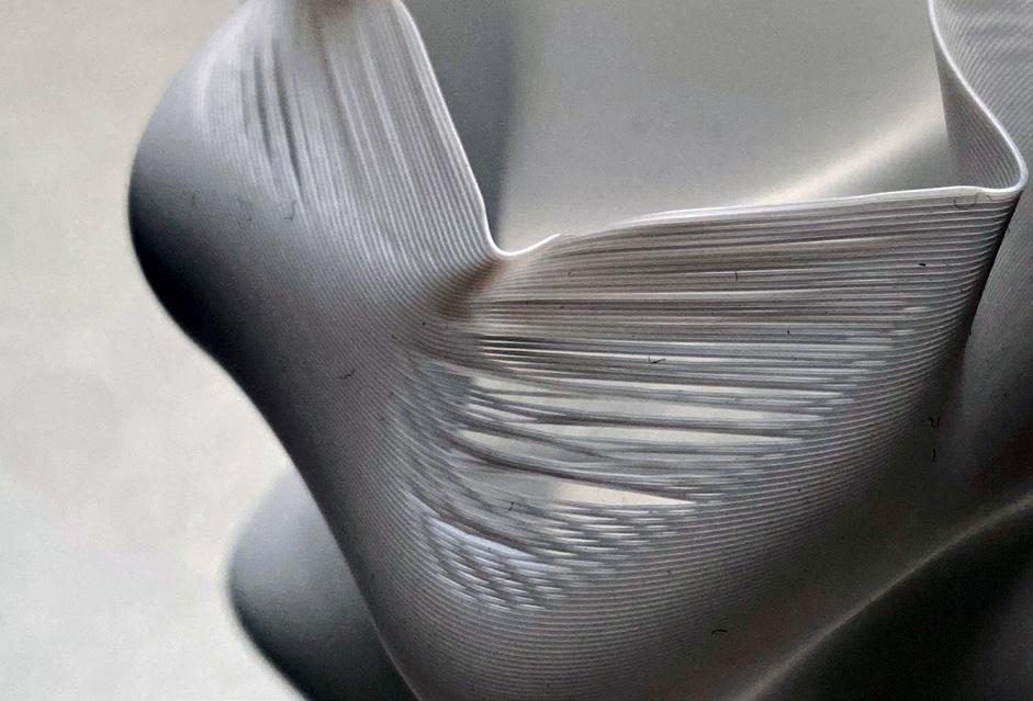
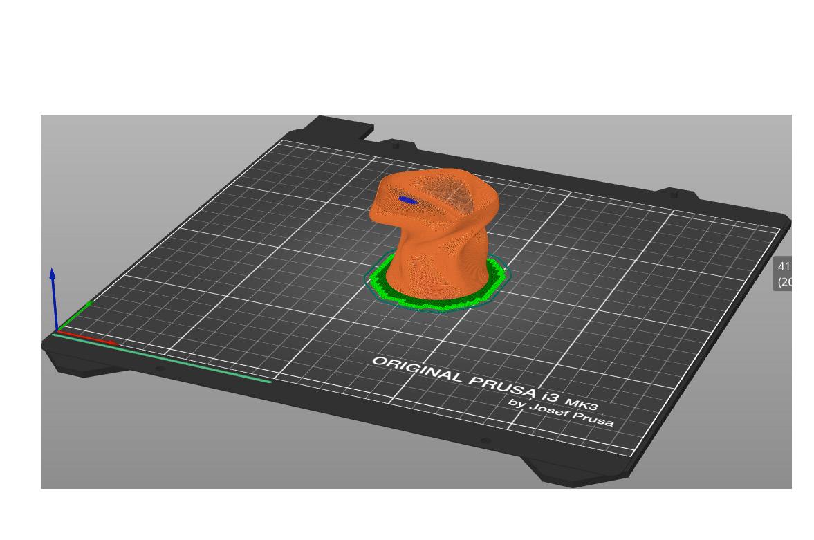
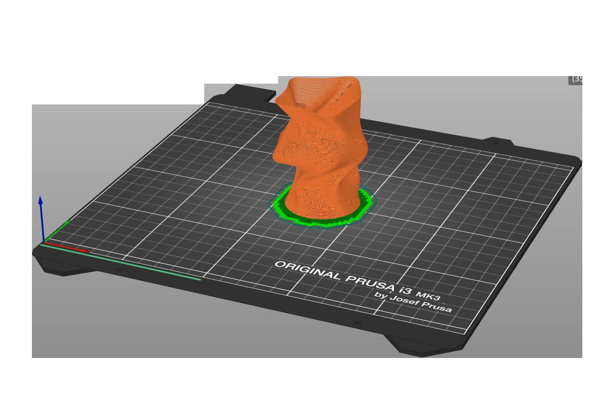
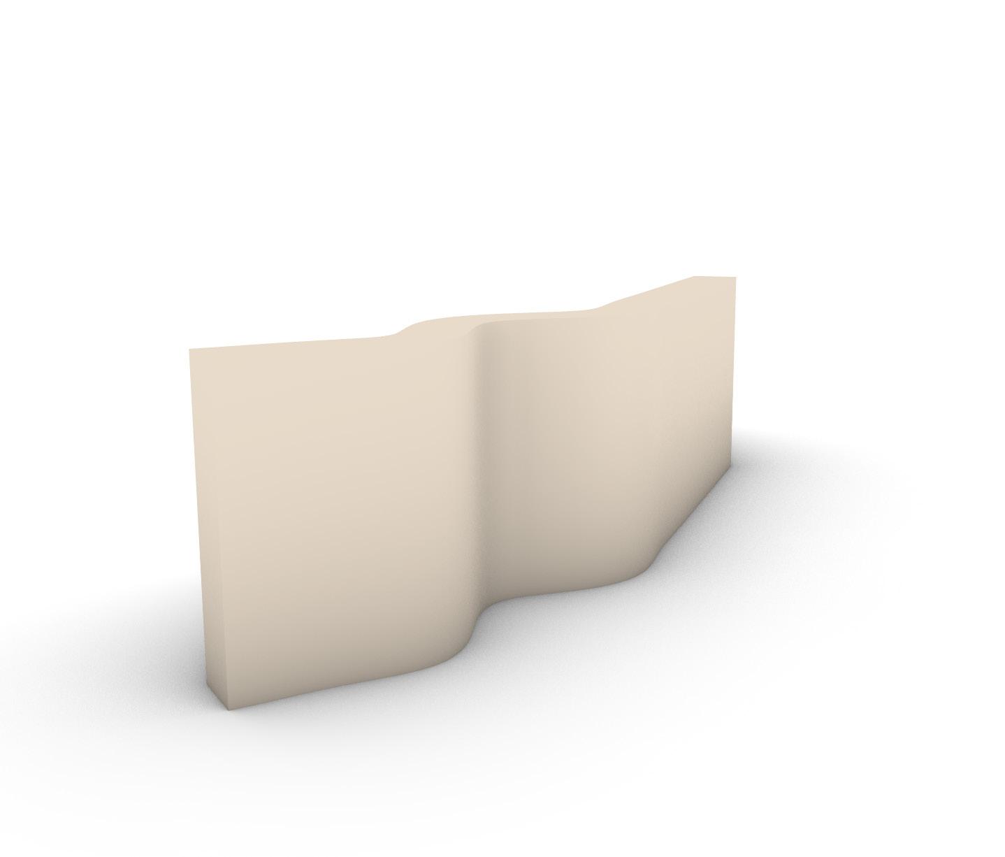
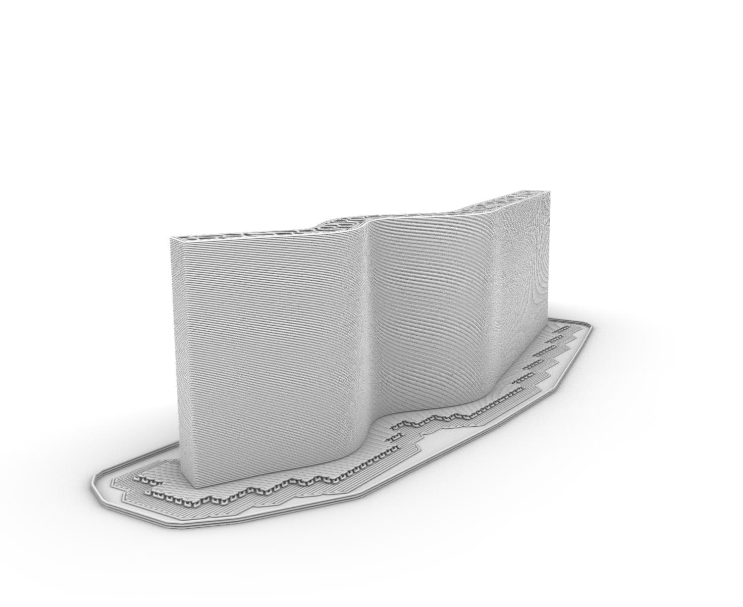
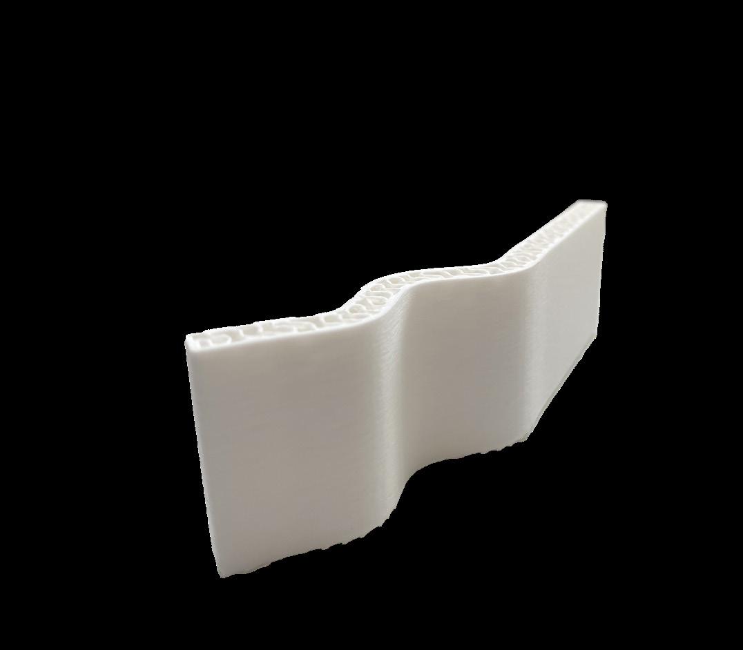
The main issues with this print were having to do with the cantilevered sections. Horizontal gaps appear at the steepest angles which disrupts the prints air-tightness. A wider print width would possibly solve this issue for future prints. The bed adhesion was solid and the print bed pull required no clean-up.
Steps
Create circular curve at Z-0
Draw vertical line from the base
Copy base curve along vertical
Manipulate copies for varied shapes
Loft curves into surface
Cap the open surface
Export STL file
Prusa Steps
Import STL file
Choose type “vase” Select “spiral vase”
Add “raft” and “brim” Slice form
Analyze issues Export G-Code Print
3_





DESCRIPTION
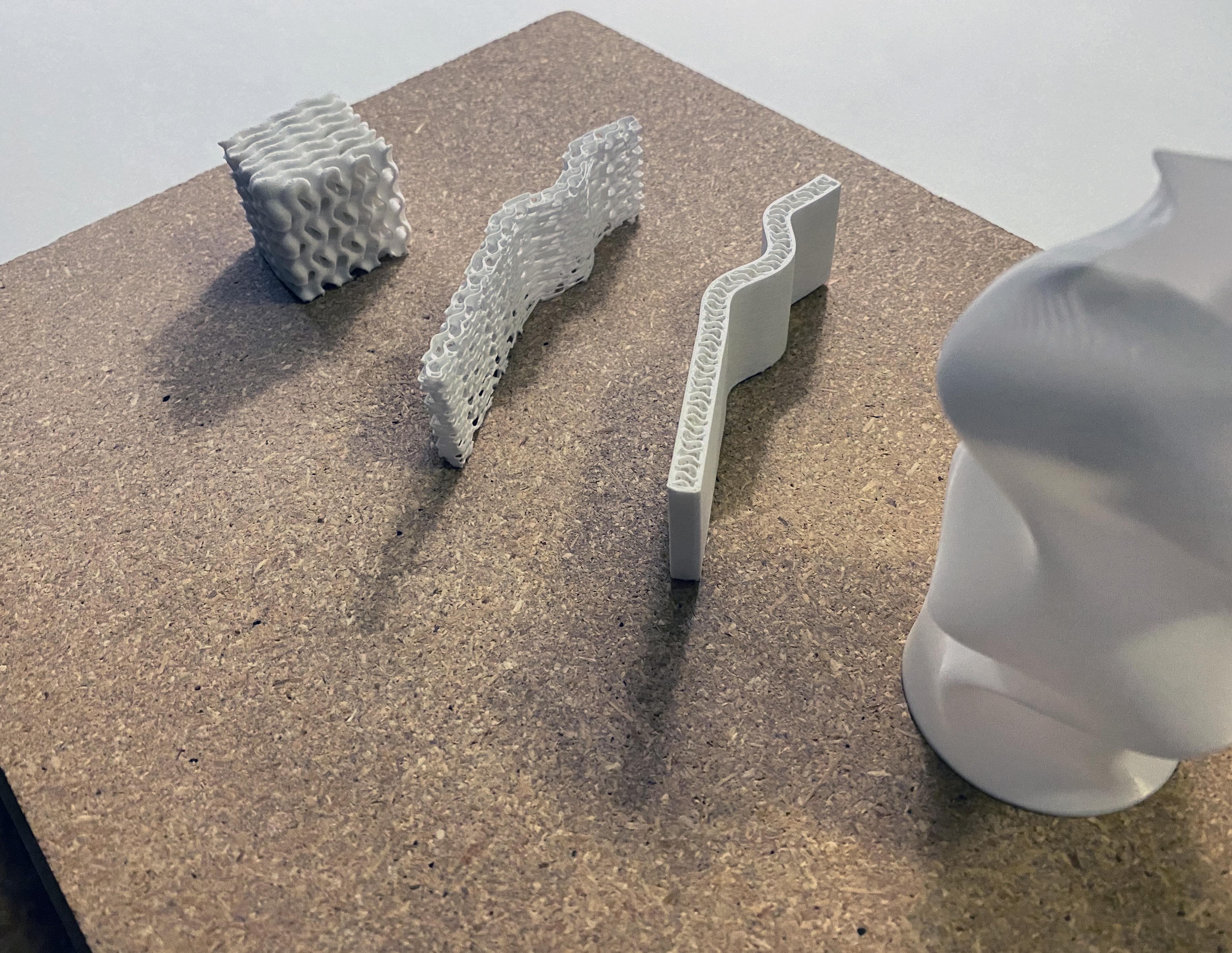
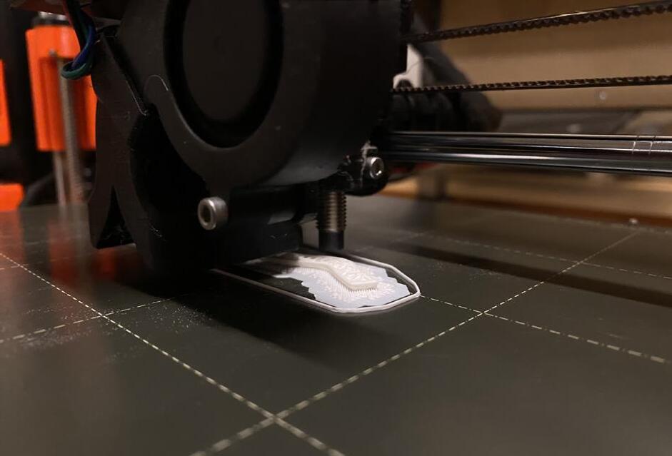
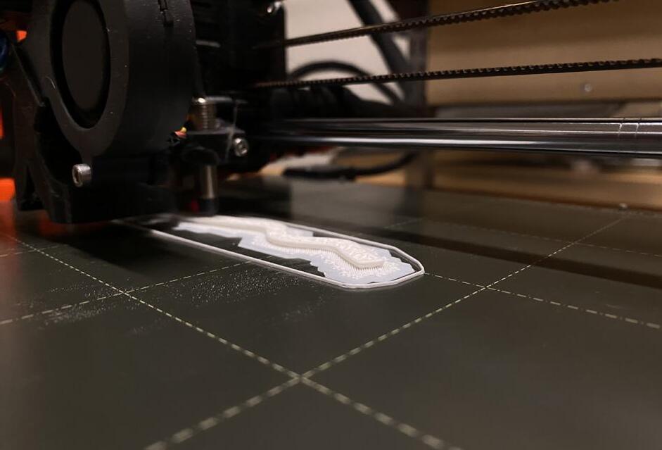
The main issues with this print were having to do with bed adhesion. The pull from the print bed was quite messy and the excess filament hairs from the raft created stability issues at the base. The gyroid infill pattern (25%) was discontinuous because of the tight wall confounds but the print was still structurally stable. For lighter and faster print, reduce infill percentage.
Rhino Steps
Create curve
Add control points to curve
Manipulate curve to undulate
Extrude curve into closed surface
Export STL file
Prusa Steps
Import STL file
Choose “infill style” Manipulate infill %
Add “raft” Remove “brim”
Reduce “top layer” to 0 Export G-Code Print
1_
2_ PRUSA Tool Path
3_ Physical Print

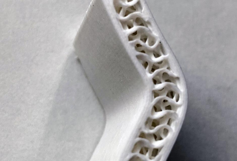


4_ Discontinuous fill pattern
5_

DESCRIPTION
An identical footprint with a reduced infill percentage (15%) compared to the “walled” infill was used to compare results. The gyroid pattern was even more discontinuous than the previous one, but the print was remarkably stable still. This was surprising given the jumpy nature of this print that picked up and started sporadically. Much cleaner bed pull compared to the previous as well.
Rhino Steps
Create curve
Add control points to curve
Manipulate curve to undulate
Extrude curve into closed surface
Export STL file
Prusa Steps
Import STL file
“Vertical shells” -> 0
“Horizontal shells” -> 0
Manipulate infill %
Manipulate infill anchor
“Fill angle” -> 0
“Auto generate supports”
Export G-Code
1_
2_
3_ Physical Print


DESCRIPTION
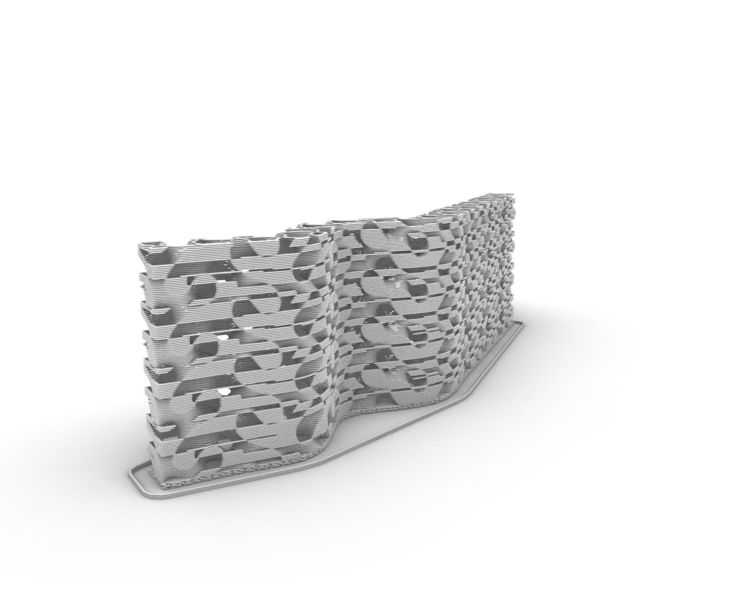
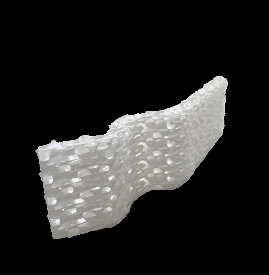
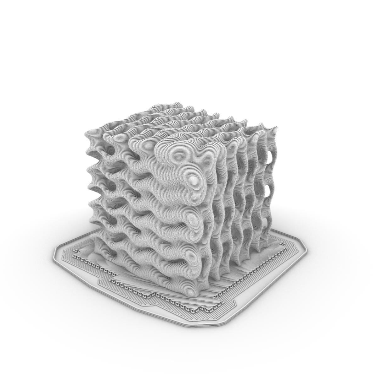
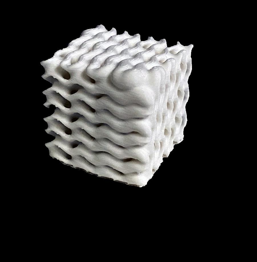
The main issues with this print were in regards to bed adhesion and raft clean-up. Lowering the undulating form below the print bed allowed for a stable start, but it also created stringing issues. The print was very structurally stable due to its undulating form and it created a very interesting wood-grain pattern on the top of the print.
Rhino /Grasshopper Steps
Open Grasshopper script
Adjust “brep” and “mesh” settings
Choose point attractors
Adjust output scale
Adjust output thickness min/max
Bake desired outcome
Export STL
Prusa Steps
Import STL file
Connect print to bed
Add “raft” & “brim” Export G-Code Print
1_ Rhino Closed Mesh
2_ PRUSA Tool Path
3_ Physical Print





DESCRIPTION
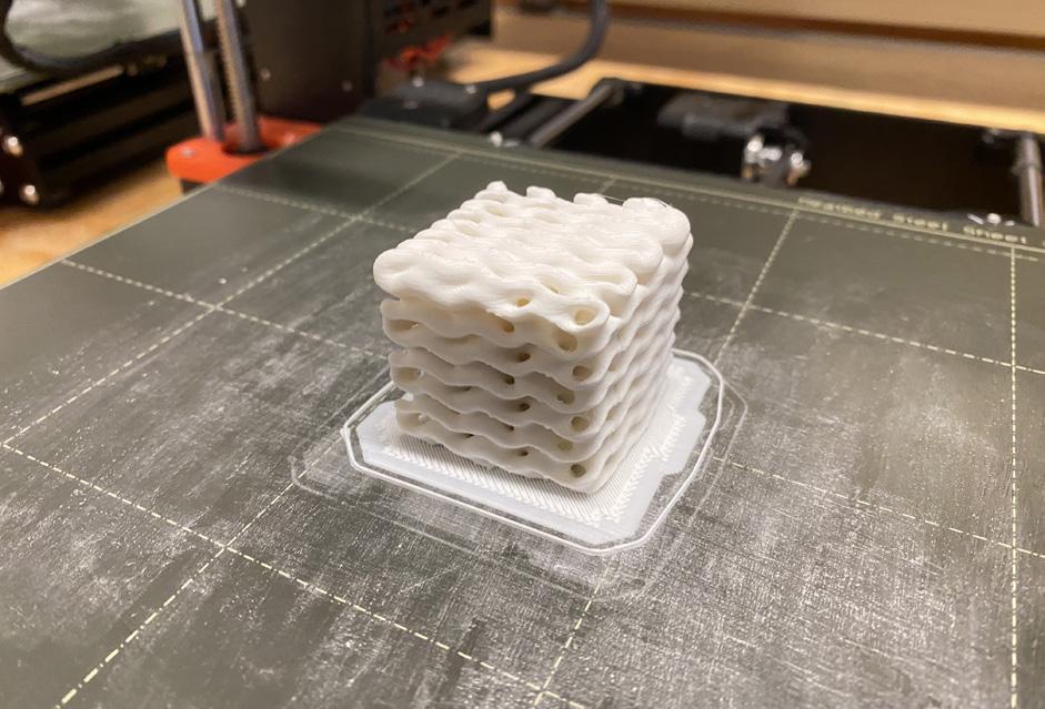
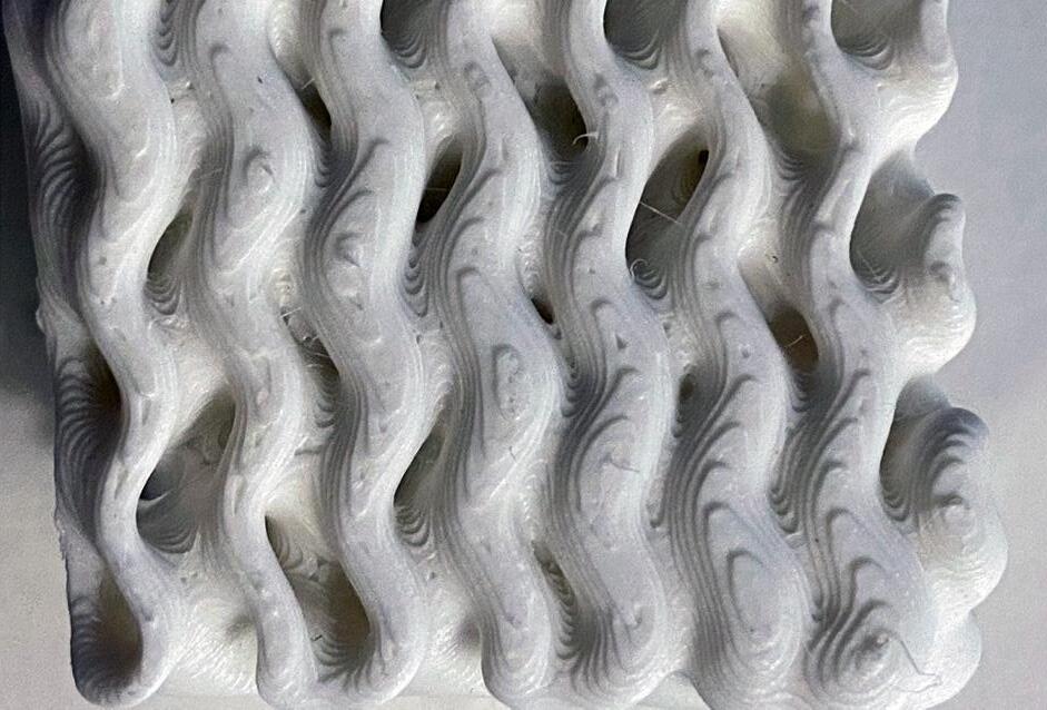
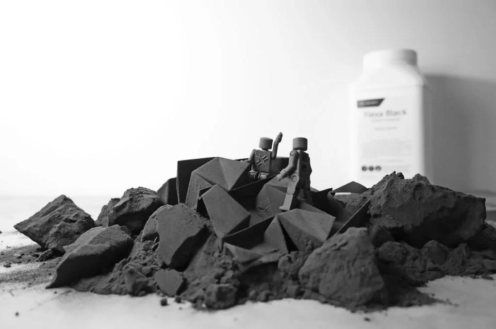
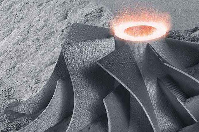
This print is identical to the previous, but it uses a different 3D printing technology (Formlabs Fuse). The process is known as ‘laser sintering’ and it is most applicable. The precision and strength of these prints allows for much wider application in sectors such as manufacturing and biomedicine.


Laser Sintering Process
Printer bed coated with powder
Laser selectively heats powder
Laser melts/fuses powder together
Print bed lowers
Process Repeats
Allow part to cool
Remove from powder bed
Move to vacuum booth
Clean unused powder
Apply surface finishing
Reuse leftover powder
1_
2_
3_
Fuse Physical Print
Fuse Physical Print
Fuse Physical Print




4_Laser Sintering 3D Formation
5_Vacuum Powder Cleaning
6_Finished Fuse Print
https://sinterit.com/blog/sls-technology/5-most-common-myths-about-sls-powder-handling/ https://www.buschvacuum.com/us/en/news-media/high-precision-3d-printing-with-metal-powder.html https://powder.samaterials.com/blog/the-application-of-3d-printing-tantalum-powder-in-biomedicine.html

3D Printed Assemblies


DESCRIPTION
REGIONAL SCALE
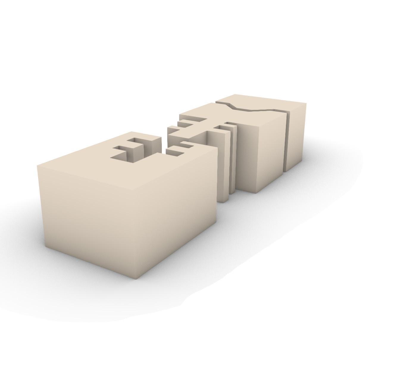
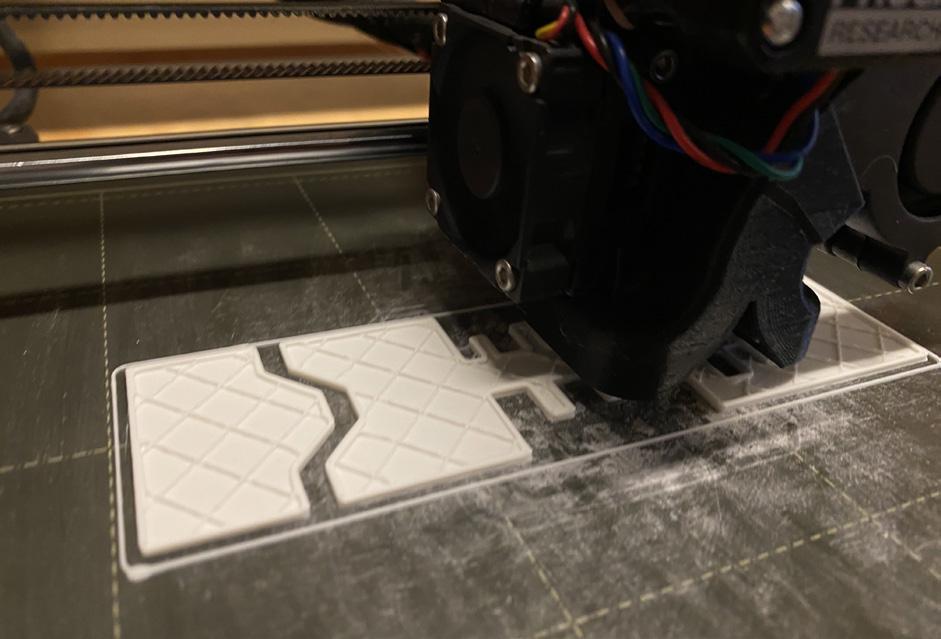
A .3mm offset was utilized for this interlocking geometry print (.15mm/ curve) to begin to explore a locking mechanism. The fit was fairly flush, but for tighter fits, a .15mm offset would be preferable. It should also be noted that some issues arise with connections on the bed-side of the print due to slight overflow past the geometry boundary.
Rhino Steps
Produce interlocking curves
Offset curves by .3mm
Correct unintended offsets
Extrude curves into closed surface
Separate surfaces for print
Export STL file
Prusa Steps
Import STL file
Choose infill
Style Rectangular
Density 5%
Export G-Code
2_ PRUSA Tool Path
3_ Physical Print



DESCRIPTION
REGIONAL SCALE
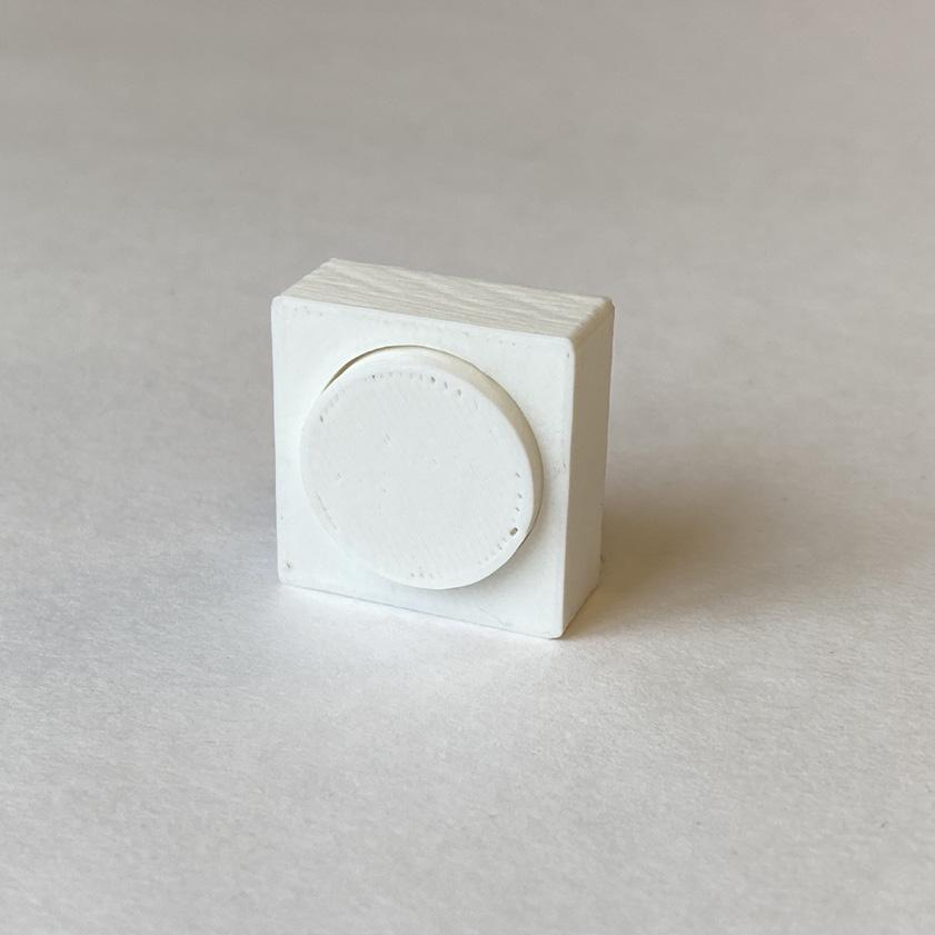
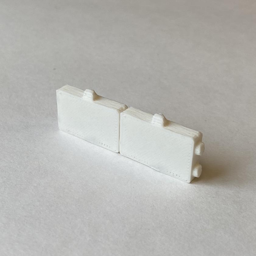
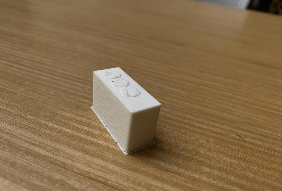
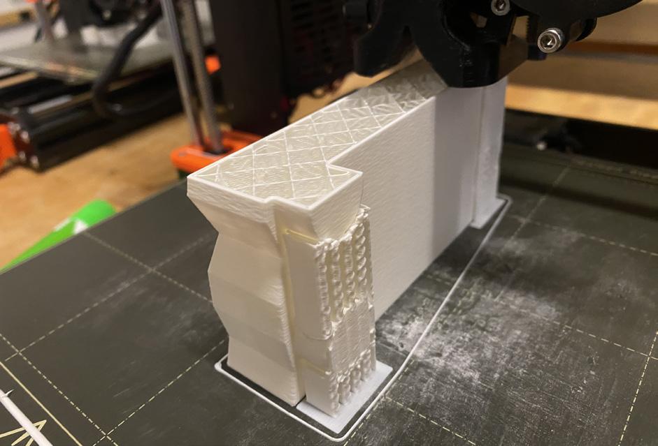
Initially, a ‘key/lock’ component was planned for the final assembly print. This concept veered from the intended aggregation of a component so it was abandoned, but it provided plenty of insights into proper tolerance fits for the dowel connections of my ‘wall’ component assembly. The initial component test print was for an insert with lock pins, which utilized a .3mm offset. As can
be seen in Figure 1, the tolerance for this rounded .3mm connection was very loose, and would not be ideal for most applications. Due to this, the dowel connection for the ‘wall’ component was reduced to a .15mm offset and tested (Figure 2). This was still not ideal for the intended application so I reduced it once again to a .075mm offset for a snug fit. In addition to these tolerance
tests, a miniature assembly of the ‘wall’ components was printed (Figure 3). Although the scale reduced the connections to be nearly unusable, it provided a basic understanding of the different connection conditions throughout the ‘wall’ assembly.
1_ Component 1 Trial (.3 mm offset)
2_ Component 2 Trial (.15 mm offset)
3_ Component 2 Mini-Assembly





DESCRIPTION
REGIONAL SCALE
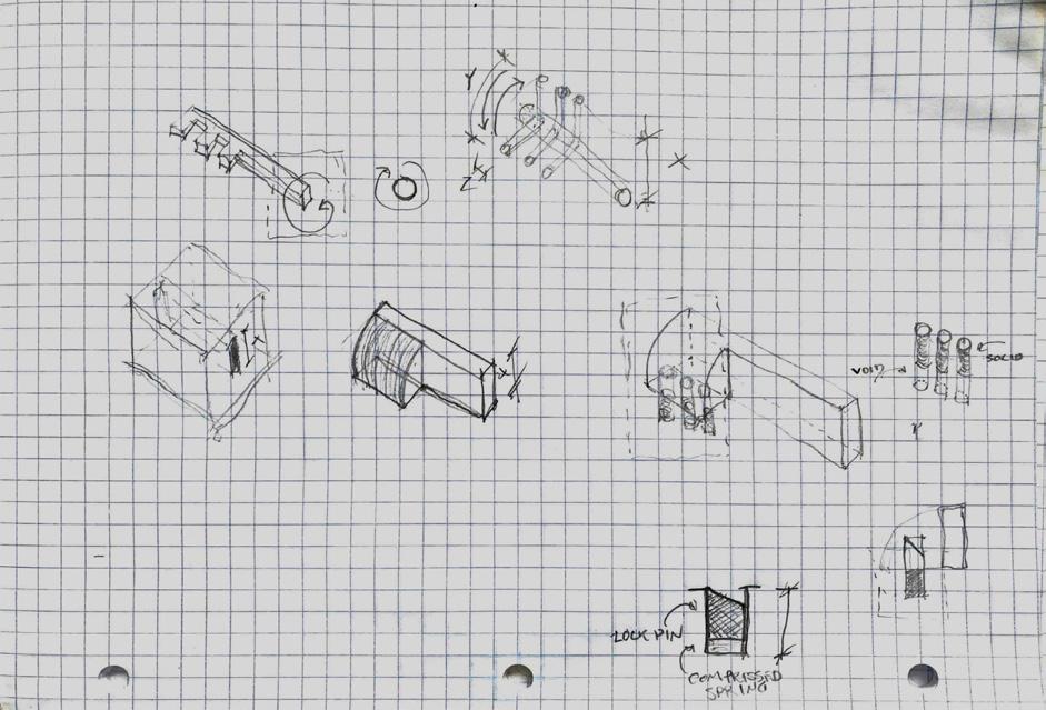
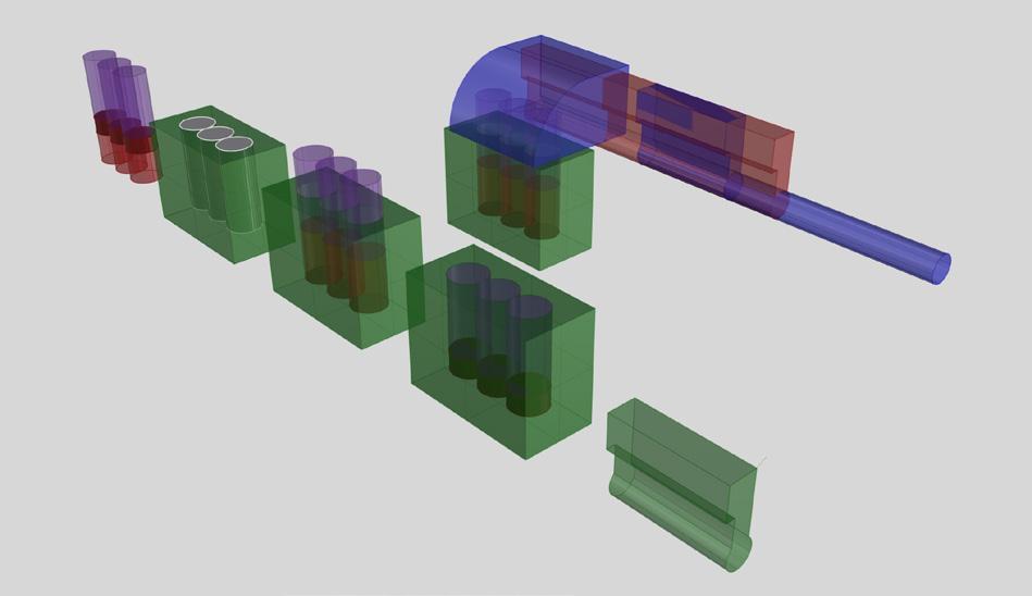
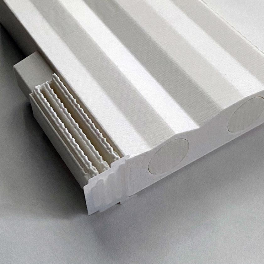
A standard component, with vertical and horizontal connections, was the first to be printed. This print was oriented on its side, due to a reduced print time, but the filament direction for the finish pattern was not ideal with this print direction. In the following prints, an upright position was maintained, and the finish and patterning of the components were much cleaner. In
addition to this improvement in surface finish, the upright print position also provided a different internal support pattern that can be seen when held up to the light. This difference in light-play and finish quality is something that needs to be considered at all scales, but at a larger architectural scale this is even more important, because the structure and load paths of the
components would differ. Besides some slight issues with the cleanliness of bottom facing surfaces, the prints were successful and the automatically generated support forms were easy to clean. What would be the ideal formation of these supports at an architectural scale to reduce material cost and cleaning labor?
1_ Standard Component
2_ Prusa Support Formation
3_ Incorrect/Inverted Tenon



4_ Comp. 2 Initial Design
5_ Comp. 2 Connection Design
6_ Corner Component Design


DESCRIPTION
REGIONAL SCALE
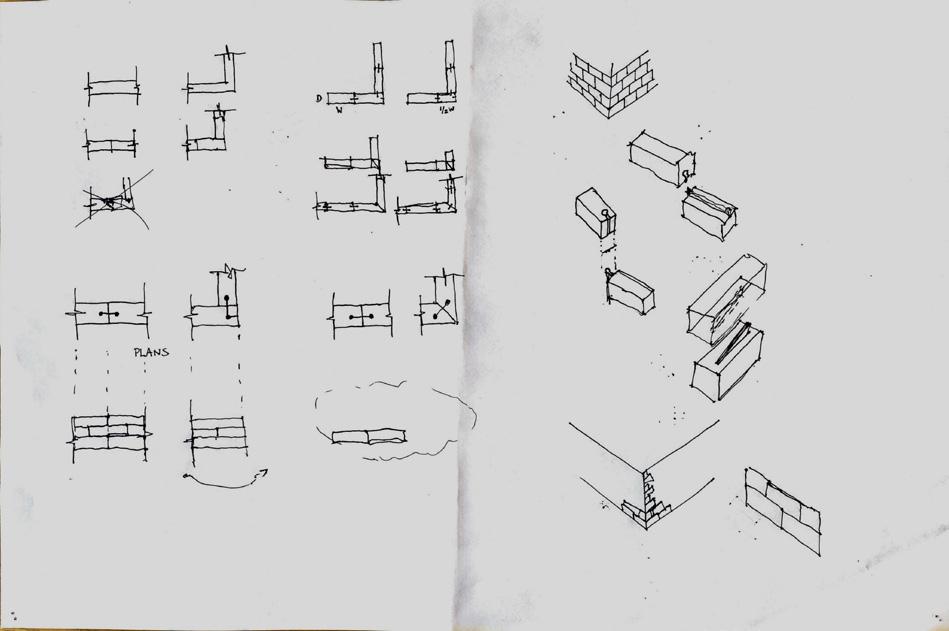
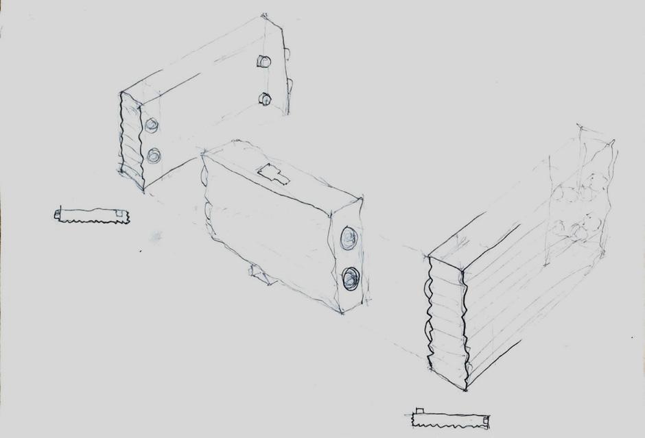
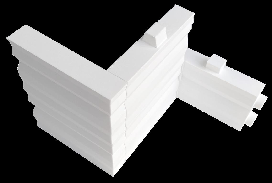
The initial standard component that was printed had a mistakenly oriented tenon connection, Paying very close attention to connection orientation is crucial for successful assemblies. In addition, the sequencing of connections also must be carefully analyzed. For instance, the ‘mortise’ connections drop vertically into the ‘tenon’ channels and slide horizontally
within the channels to lock. The sequence of this connection is misaligned with the simpler ‘dowel’ connections. This is most evident in the corner components, where the geometry makes it impossible to complete both connections without flexing the components and likely breaking there male parts. In addition to improving the connection sequencing of
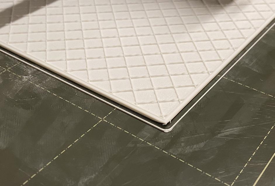
components, the structural integrity of them could also be improved by increasing the number of perimeter layers in the printer settings. 2 perimeter layers were used on the individual components, while 4 were used on the final assembly for this very reason.
1_ Vertical Connection
2_ Outside-Corner Connection
3_ Inside-Corner Connection




DESCRIPTION
REGIONAL SCALE
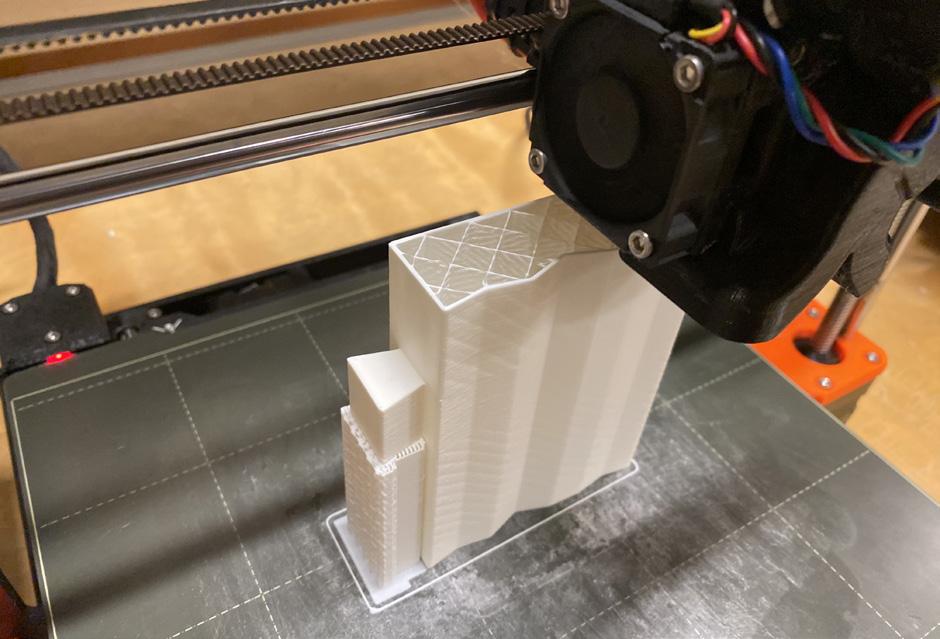
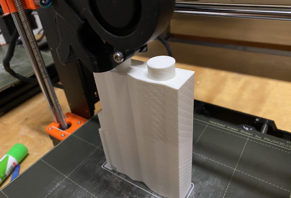
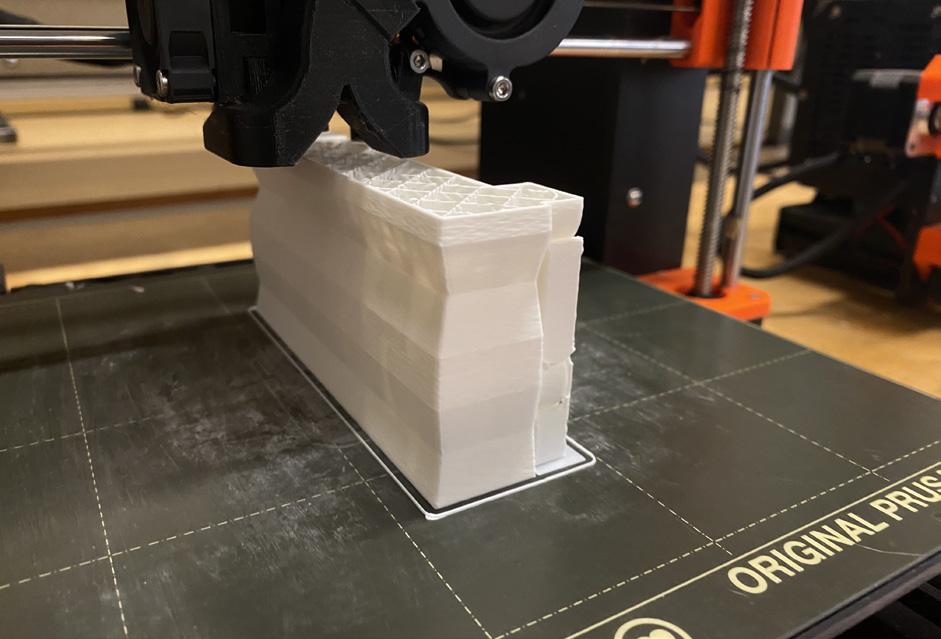
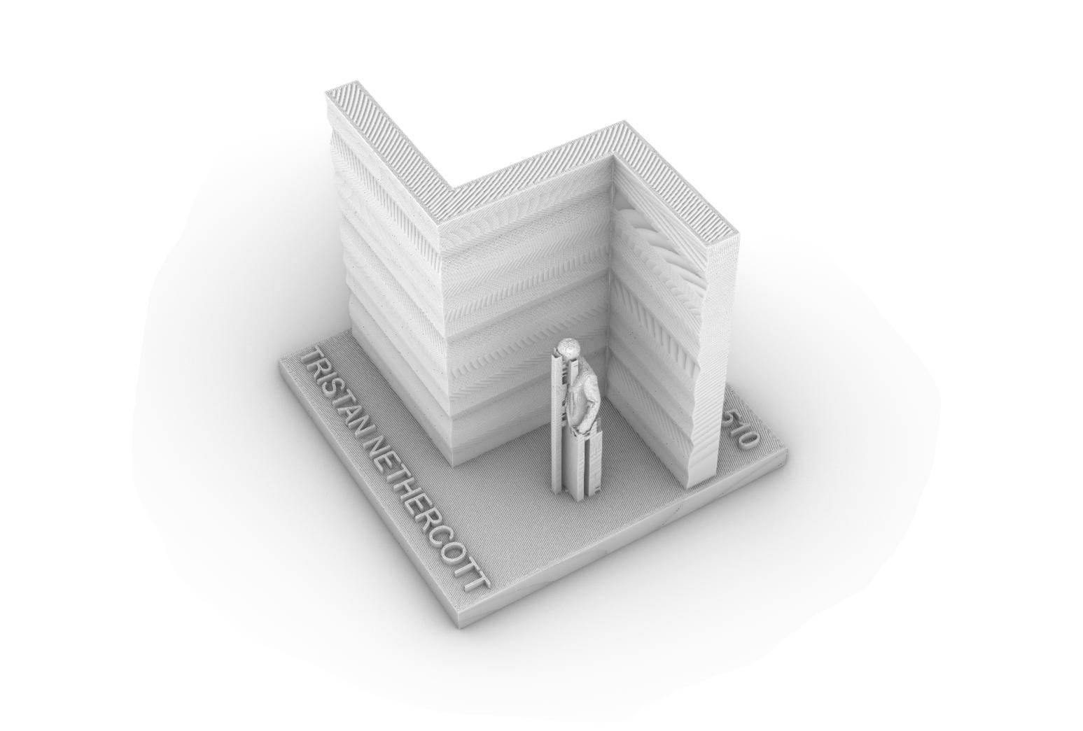
The final assembly aggregates the various components into a cohesive form at an architectural scale. 3 components stack upon each other to form a 5’ x 9’ x 1’ wall module. This module can then turn the corner both internally and externally, creating a cohesive wall form that has an infinite number of aggregation options and a high level of scalability. Ideally, the component
design at this scale would provide wall cavities within for a rainscreen and insulation layers. Beyond this building scale, the components can be scaled down to be used as enclosure cladding or even finish material such as backslash. One thing that should be considered is the size of the various connections at different scales. At the printed scales, the connections work well,
but at its largest ‘wall’ scale, these connections would become overly bulky and difficult to operate without heavy machinery. Ideally, these would be redesigned so that a small team of laborers could complete a small house assembly primarily by hand, in a similar fashion to framing a simple wall.
2_
3_




4_ Rhino “human-scale” options
5_ Prusa Print-Preview/Scale Decision
6_ Broken Connection - Increase Perimeter #

