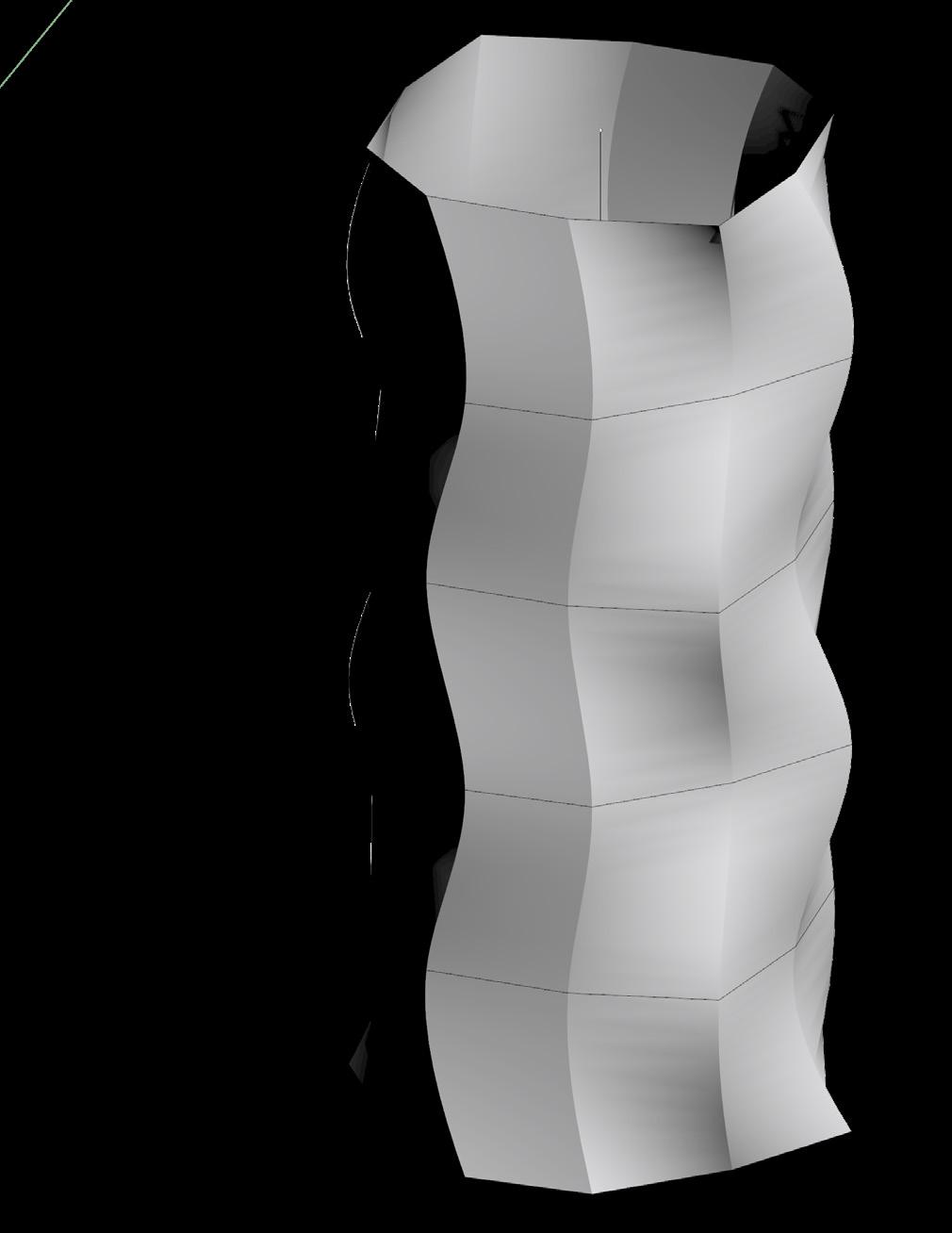
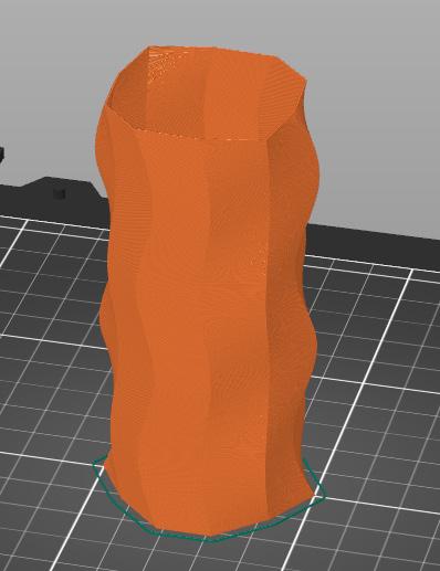
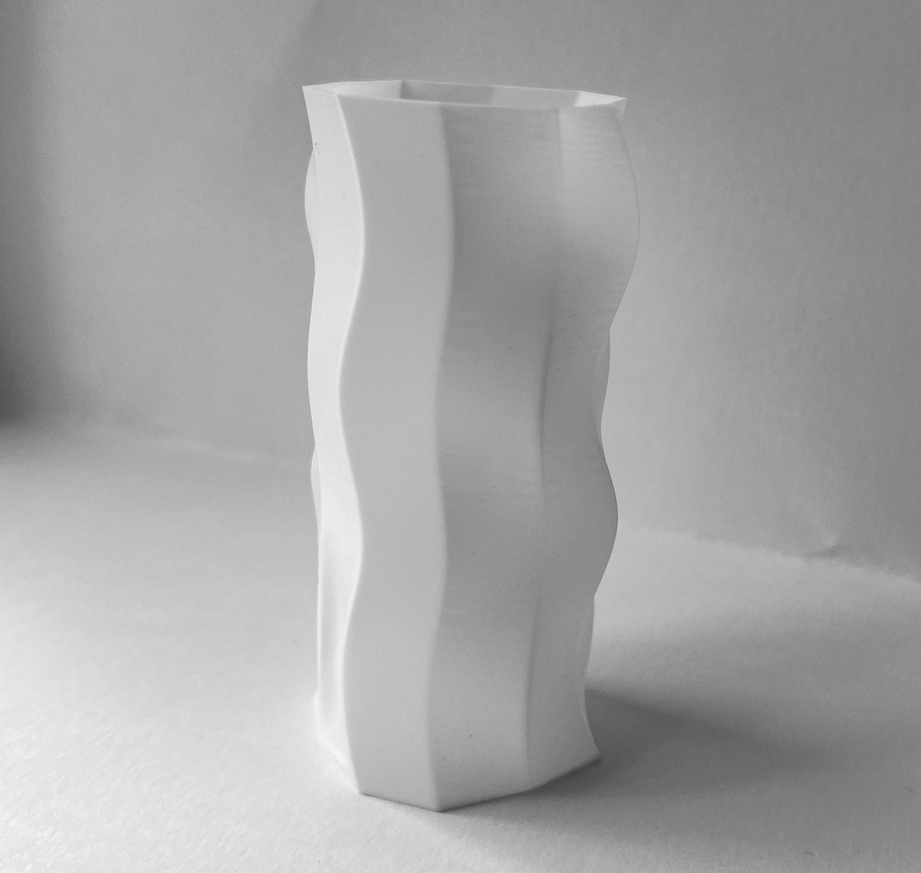
The design process for this vase started with an ellipse. Adding control points in Rhino I was able to make the form more geometric with 10 flat sides (figure 01). Rotating the shape 45 degrees and copying it up five more times, I was able to loft them together to create the shape (figures 02 and 03). Preparing for 3D printing, I made sure to cap the object to give it a base. then took
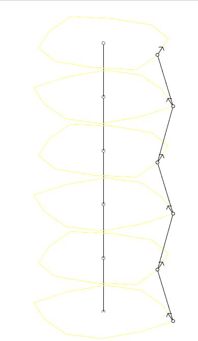
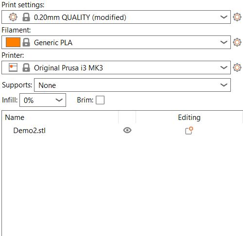
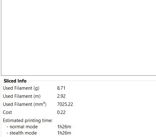
my form and exported selected and saved it as an .stl file. Opening the file in the Prusha Slicer program, I removed the infill under the “print settings” tab. While my mass printed well with no layering issues, I did have some problems getting the filament to stick to the base of the 3D printer which I fixed a glue stick.

DESCRIPTION
OBJECTS WITH INFILL
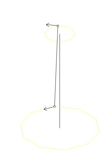
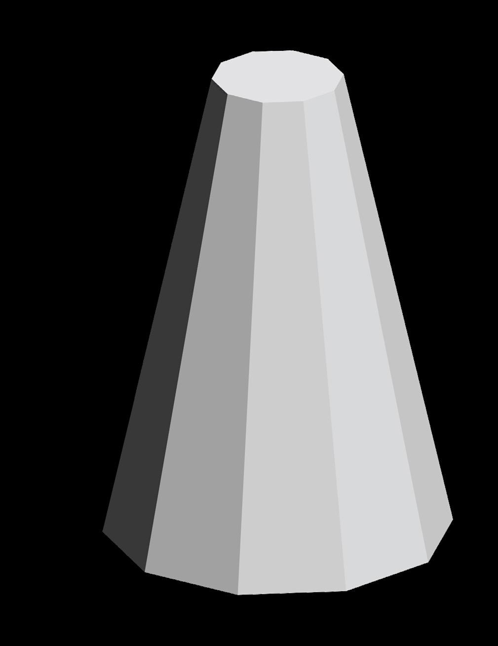
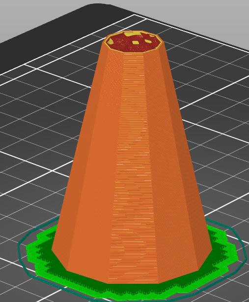
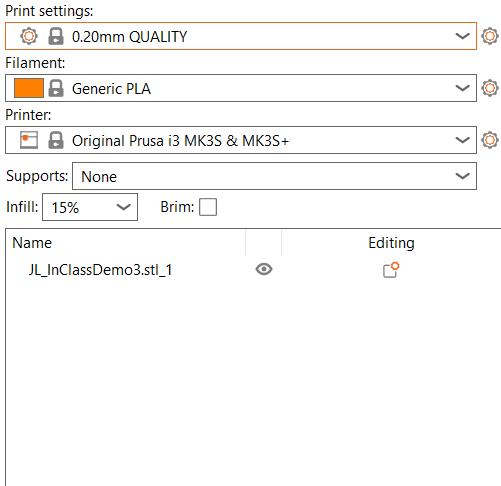
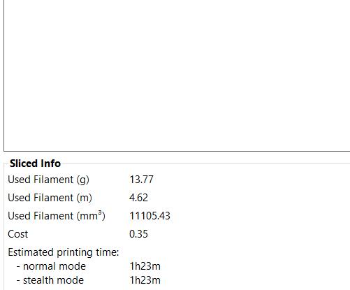
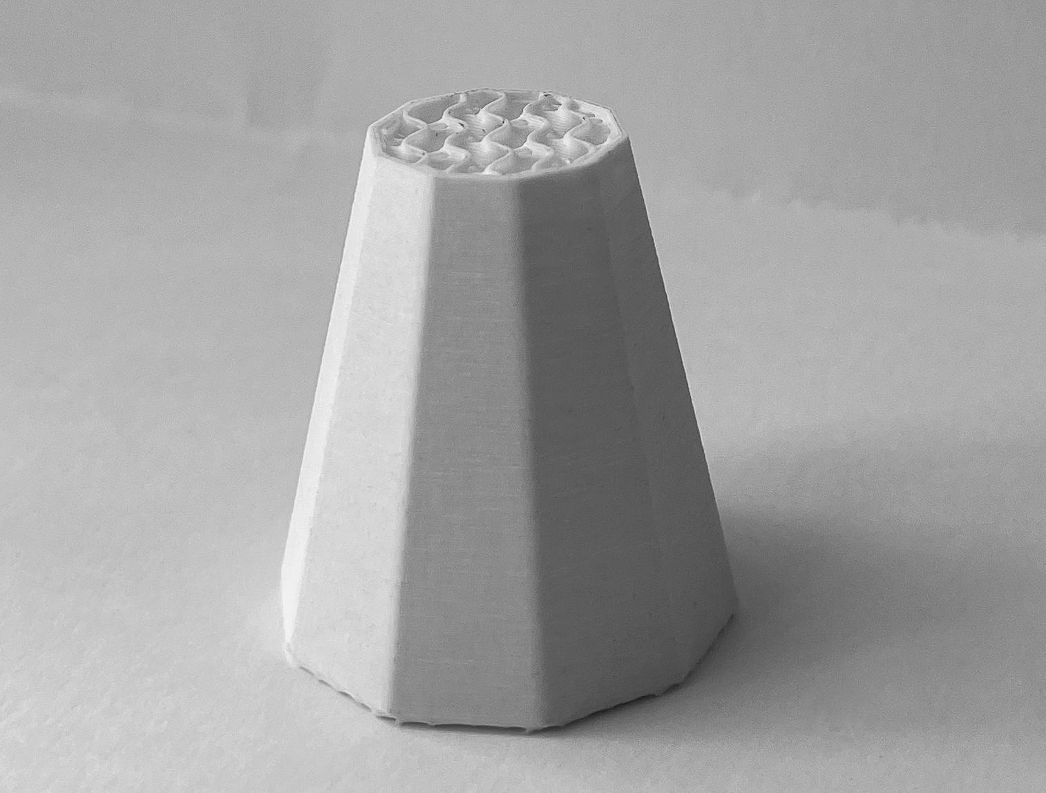
This model looks at printing with infill. I created a new 10 sided closed polyline (figure 07) and lofted it to a smaller version above itself (figure 08). I then capped the shape to create a solid form and exported selected as an stl file and opened document in Prusha to get ready to print the object. For this model, I applied a 15% gyro infill and a base to give the object structure

(figure 10). It is important to check how the infill is meeting the sides of the walls to make sure the print and bridging is successful. My print turned out well however the infill was dense at the top of my model and I could’ve probably done 5-10% infill.

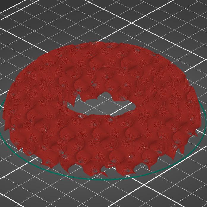
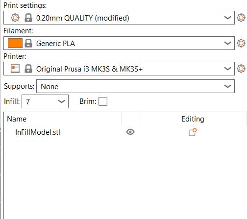
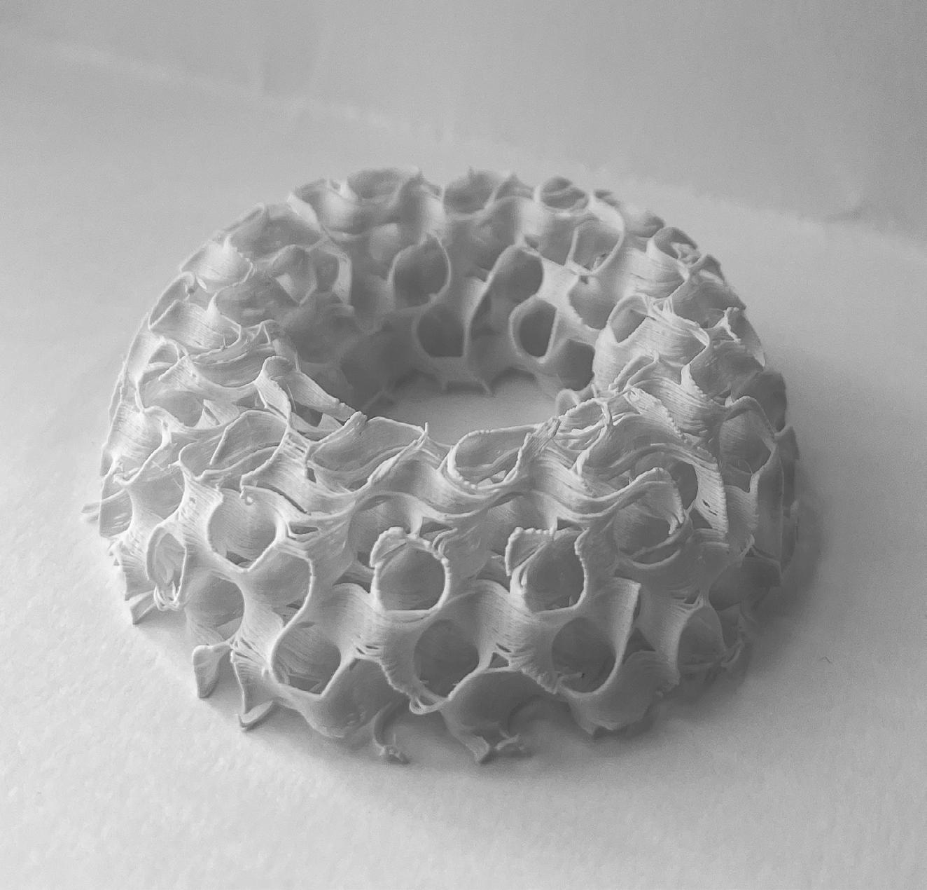
DESCRIPTION to the print bed. My infill was set to 7% and the gyroid pattern again (figure 15). When removing the print from the bed it is best to use a putty knife or a similar tool and allow it some time to cool down can to help the filament fully cure
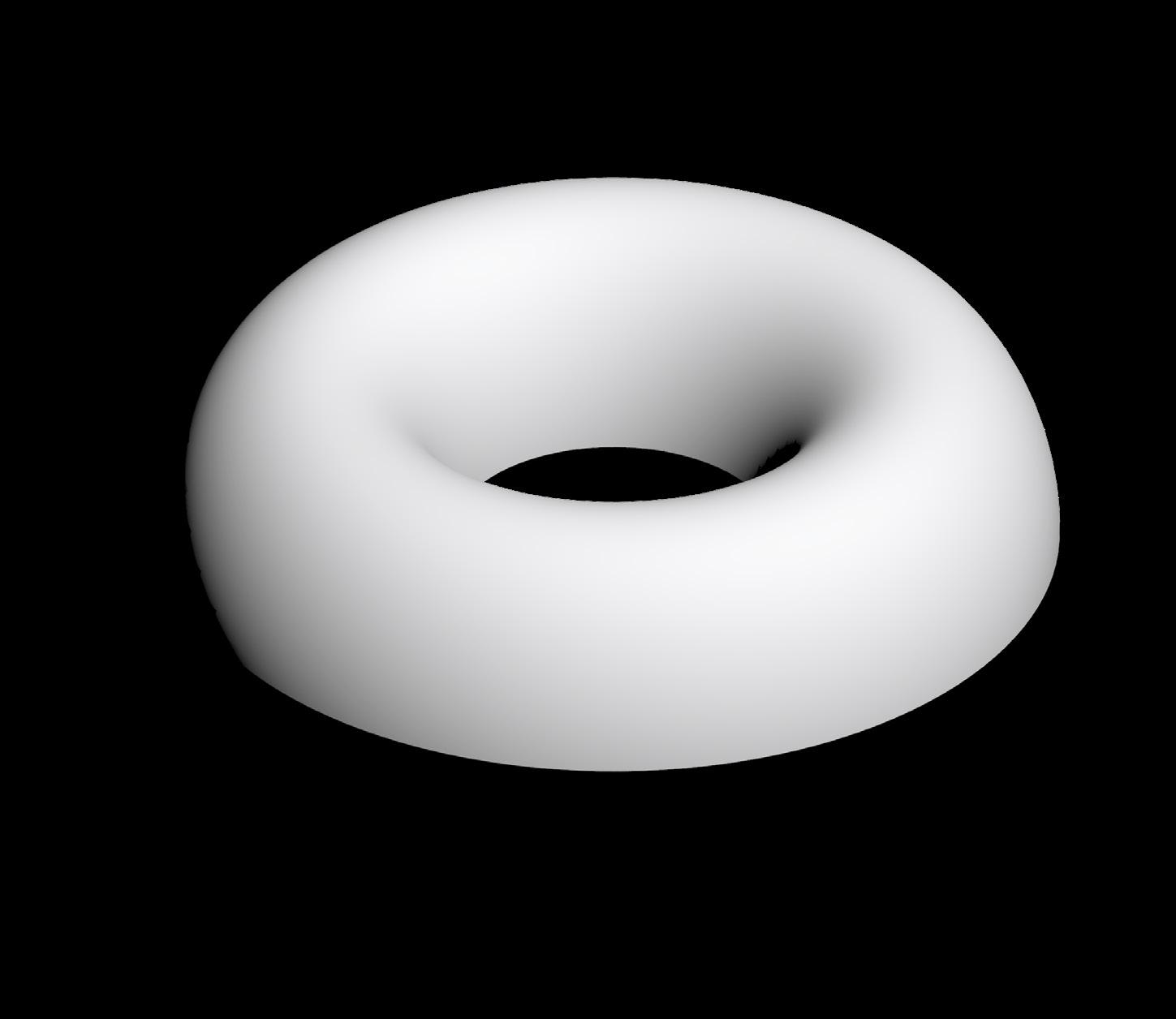
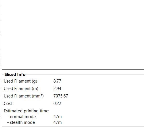
For this shape used the torus tool in Rhino where I then took the central circumference and use the wirecut command to cut the shape in half (figure 13 and 14). When printing just infill I had to change the maximum length of the infill anchor from 8mm to 1mm. Because the object is so delicate, having lots of anchor points helps the print be successful and ultimately have a good connection
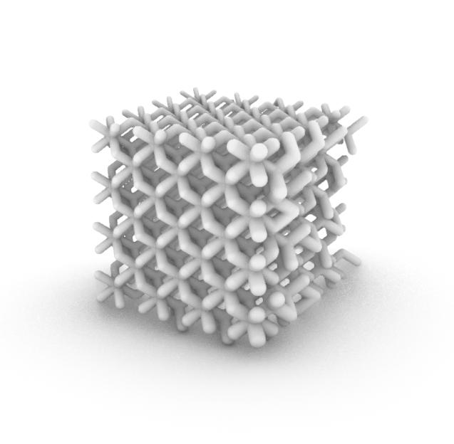
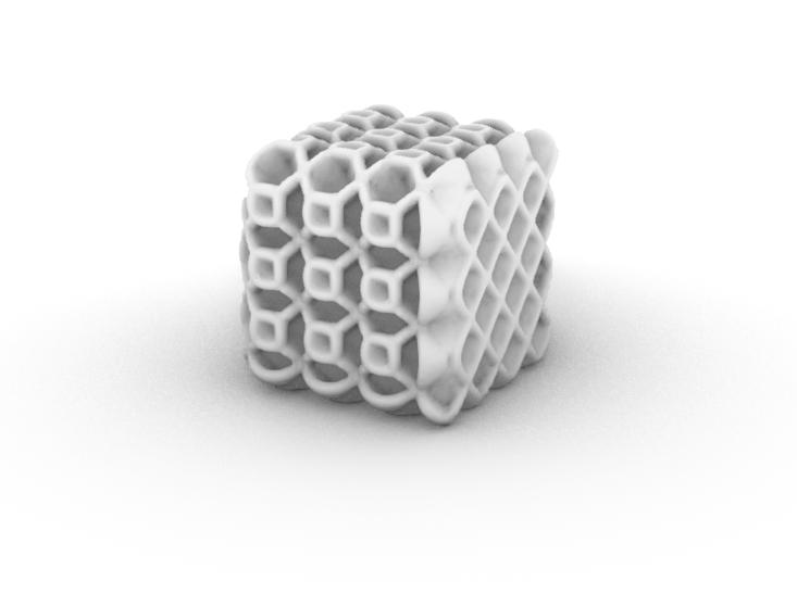
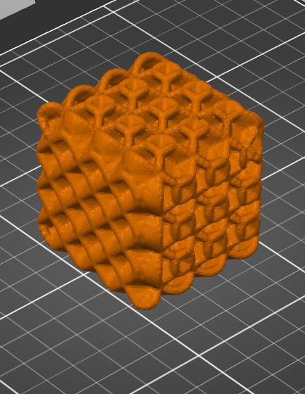
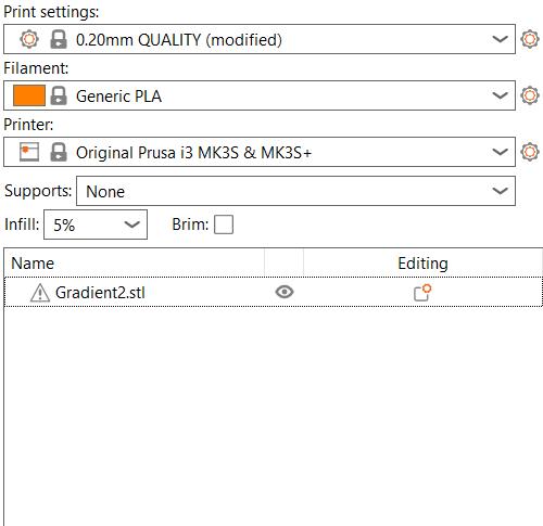
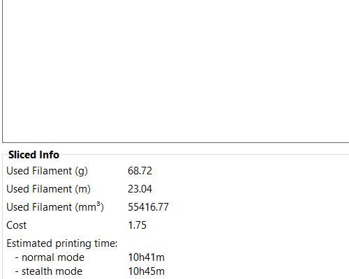
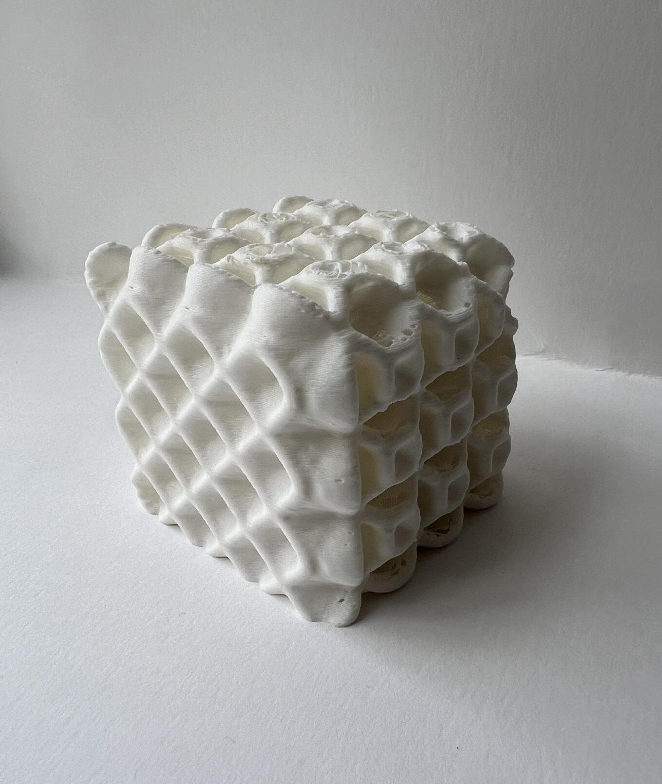
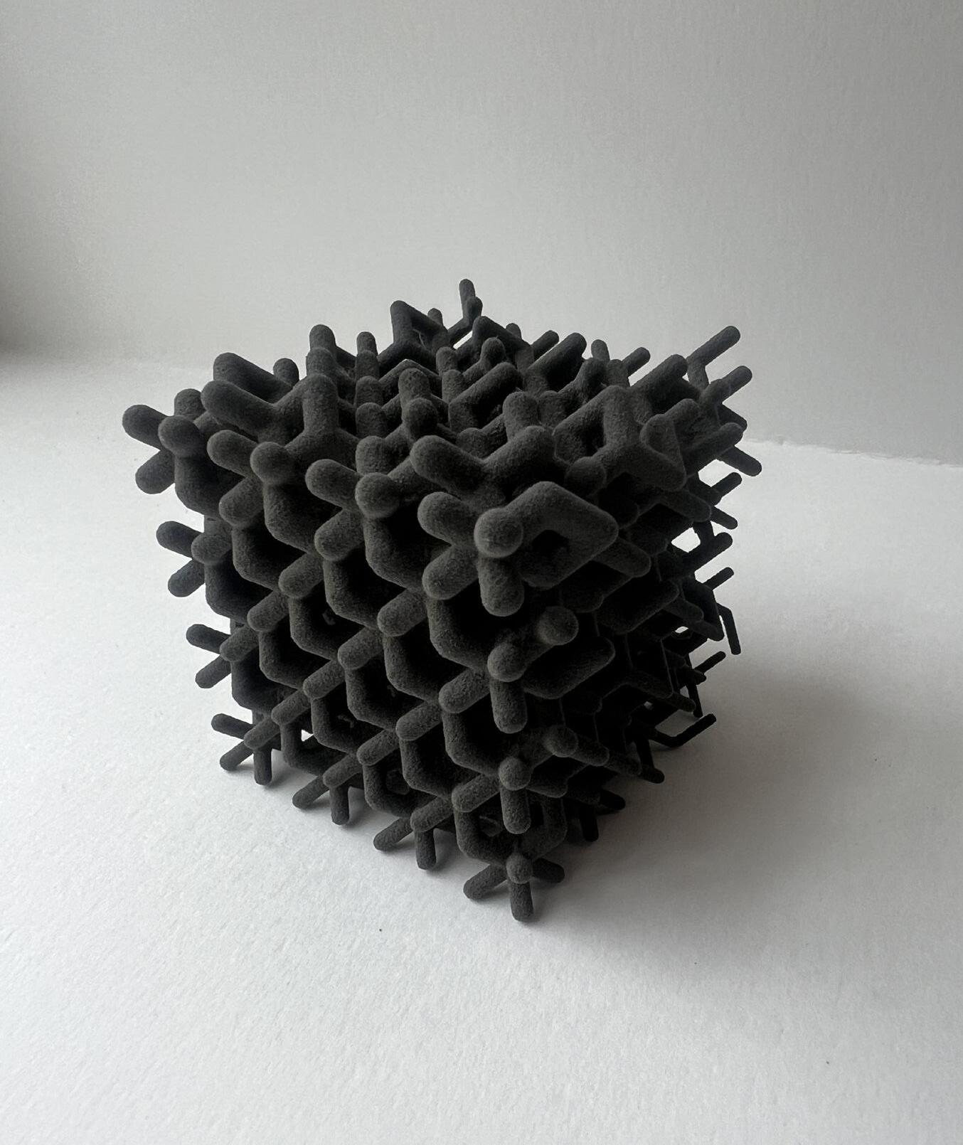
The final print of module 1 looked at 3D printing from parametric design using grasshopper. The program allowed me to creating the repeating and organic forms shown above (figure 18 and 19). Using sliders in grasshopper (figure 22) I was able to manipulate the form and shape of each object. One script was dedicated to shell infills (figure 18) and the other was beam infills
(figure 19). These types of prints take a very long time and use lots of supports on Prusa printers and are recommended to be made using formlabs sls printers (figure 23), which uses powders to give the print quick and easy support. After printing on the Prusa printer we can see lots of stringing on the top where the holes occur. Slowing print speed can help prevent this.

DESCRIPTION
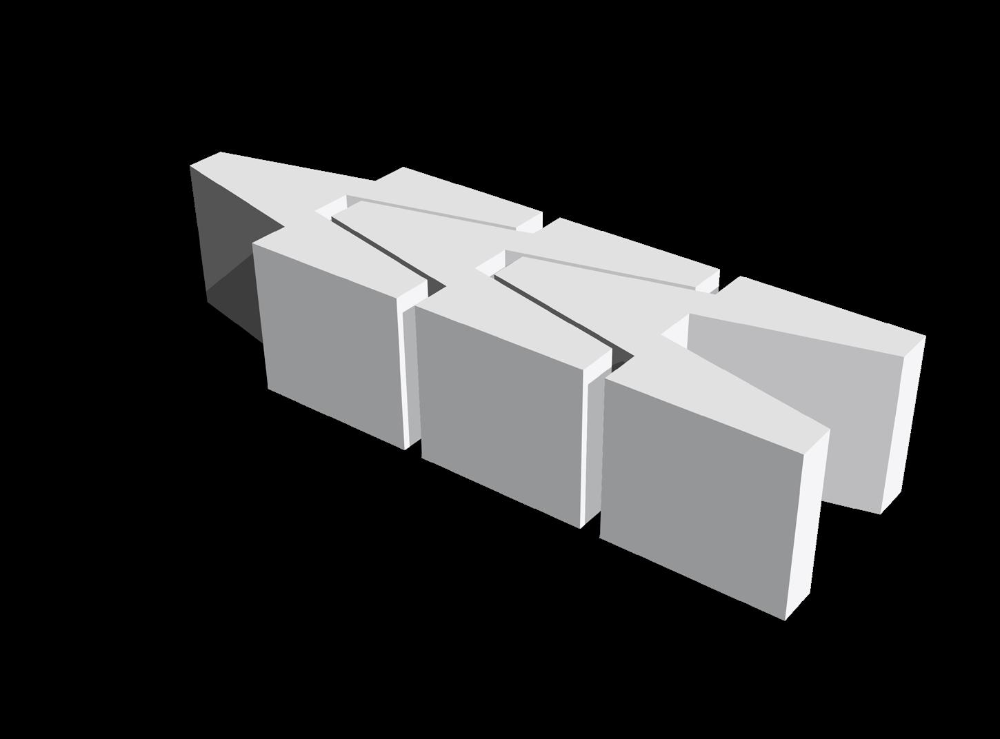
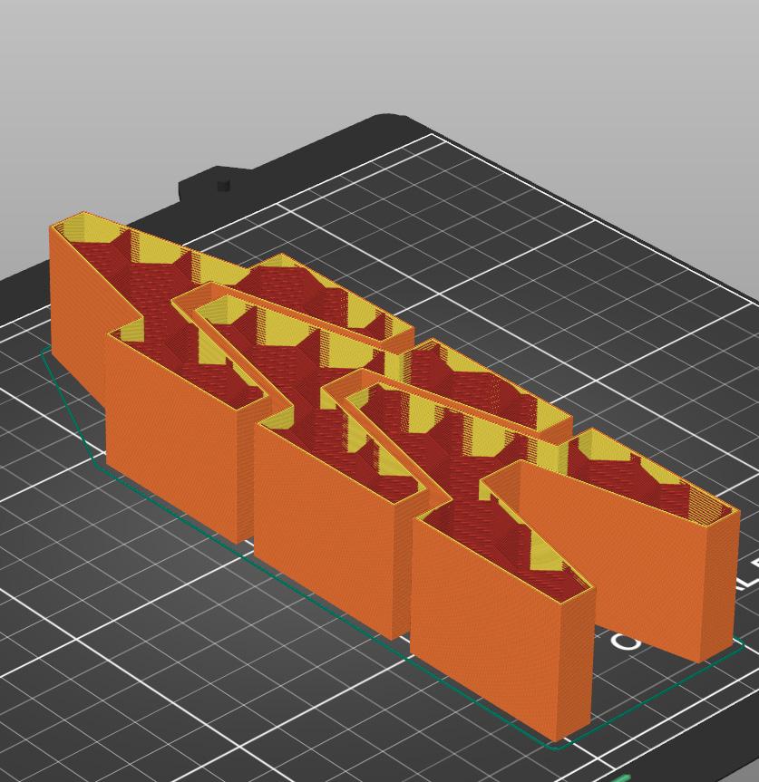
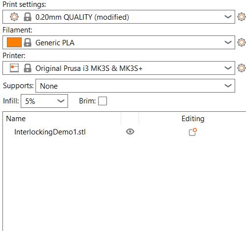
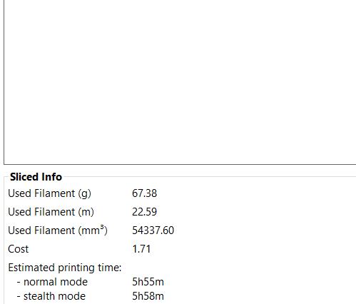
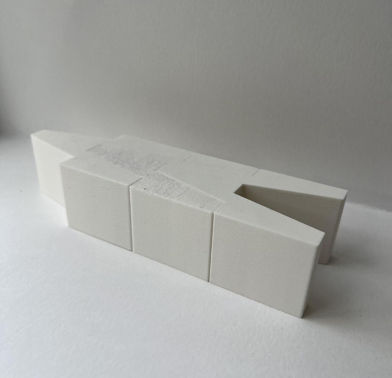
The first print for module 2 looks at the necessary tolerance needed to print interlocking components. For the print we took a rectangle which was divided up into segments (figure 24), to create interlocking pieces. That line work was then offset 0.30mm to insure the printer would create pieces that fit snug when put together (figure 25). For this print I applied a 5% hexagonal
infill in order to minimize print time while still having a strong print (figure 26 and 27). Looking at the final print we can see that a 0.30mm offset of joining pieces is a high enough tolerance to allow the components to fit together well (figure 28).
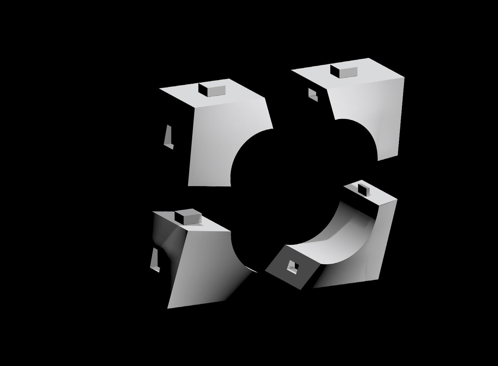
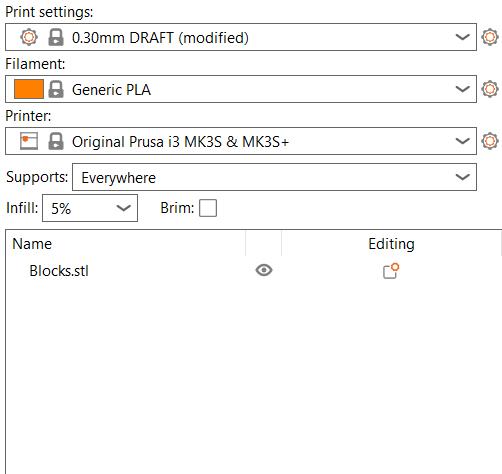
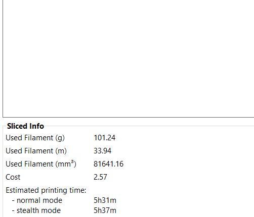
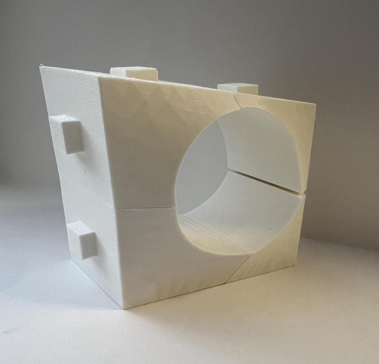
For this print we looked at creating a new modular assembly that had intricacy in the x,y, and z plane. In order to create the component, 4 rhino blocks were created and adjusted to make the shapes of the module (figure 29). The design uses mortise and tenon joints to create the connection between components with a 0.15mm offset to test minimum tolerance once more.
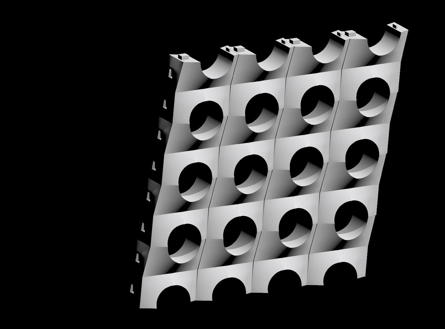
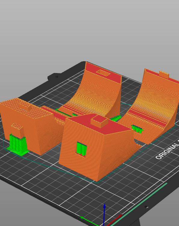
(Figure 30) shows how the component can be repeated creating an arrangement. Prusa alerted me of print stability issues so supports were added shown in green and applied a 5% gyroid infill to minimize print time (figurer 31 and 32). Looking at the final print, it shows that the 0.15mm offset only worked for 3 of the 4 pieces and the top right doesn’t fit (figure 33).
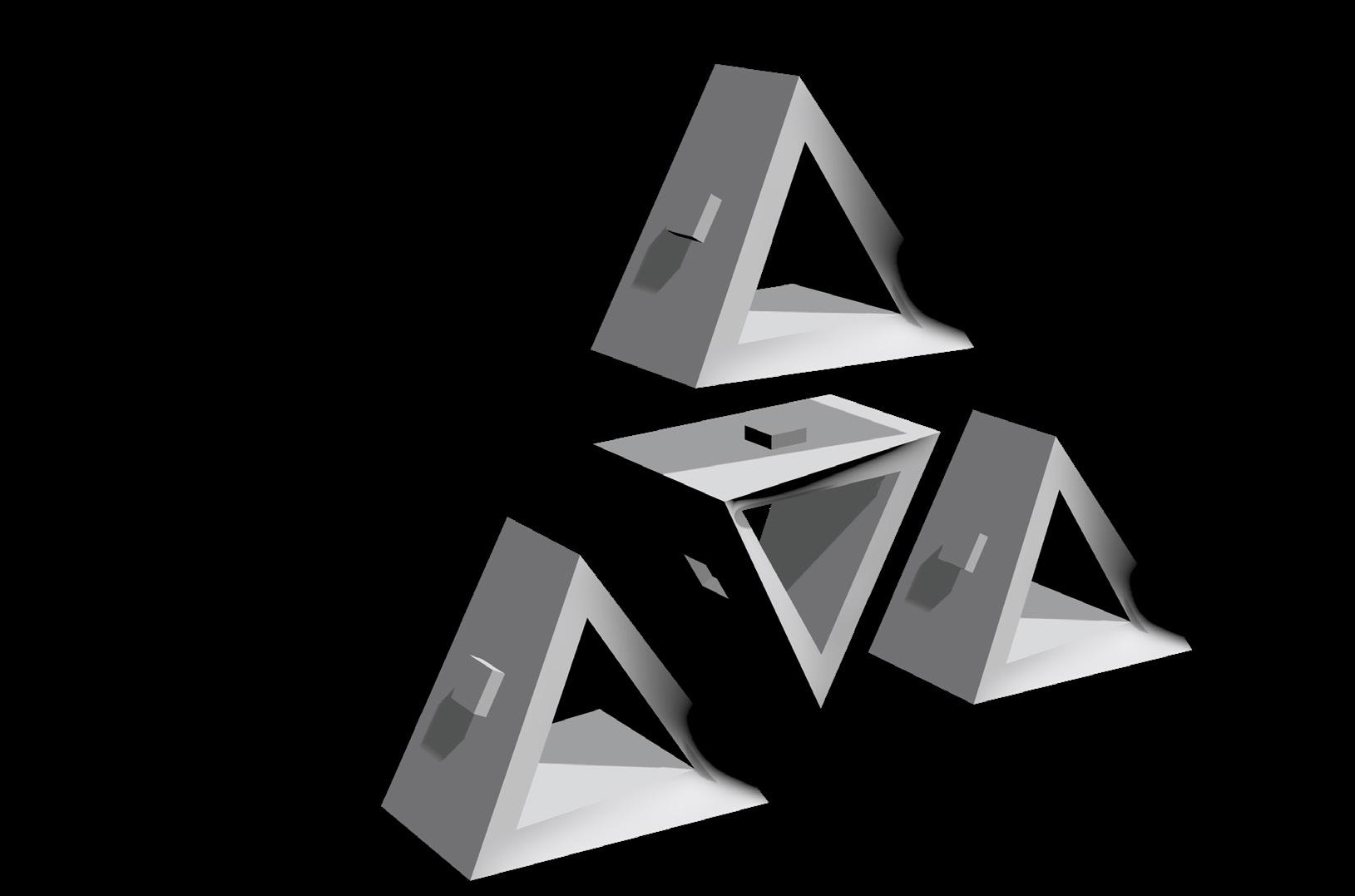
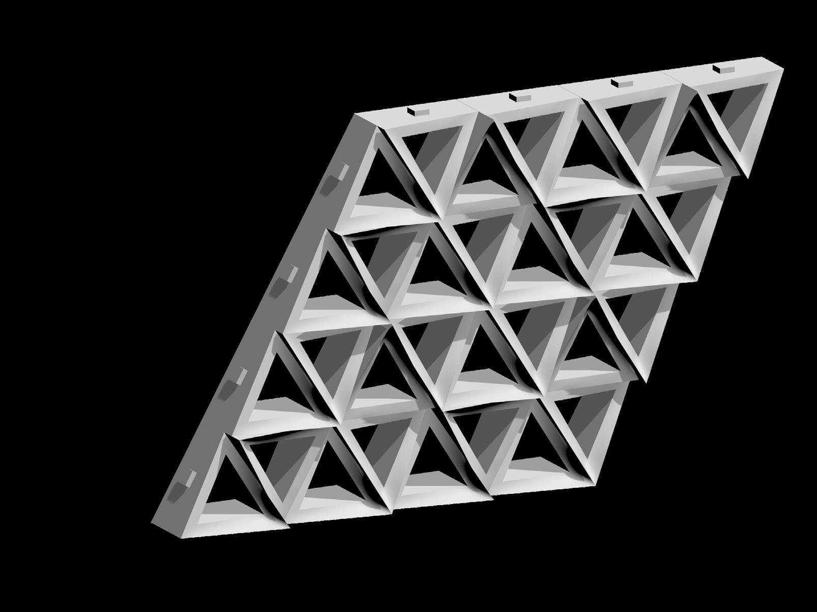
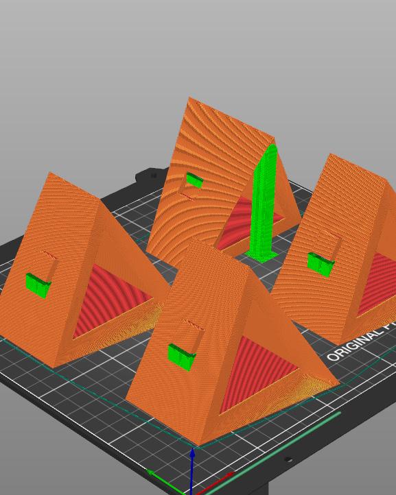

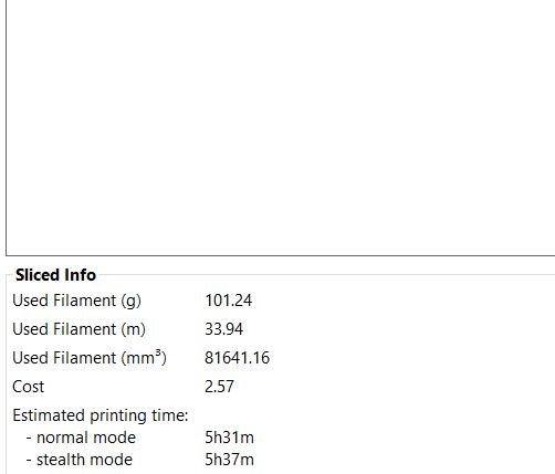
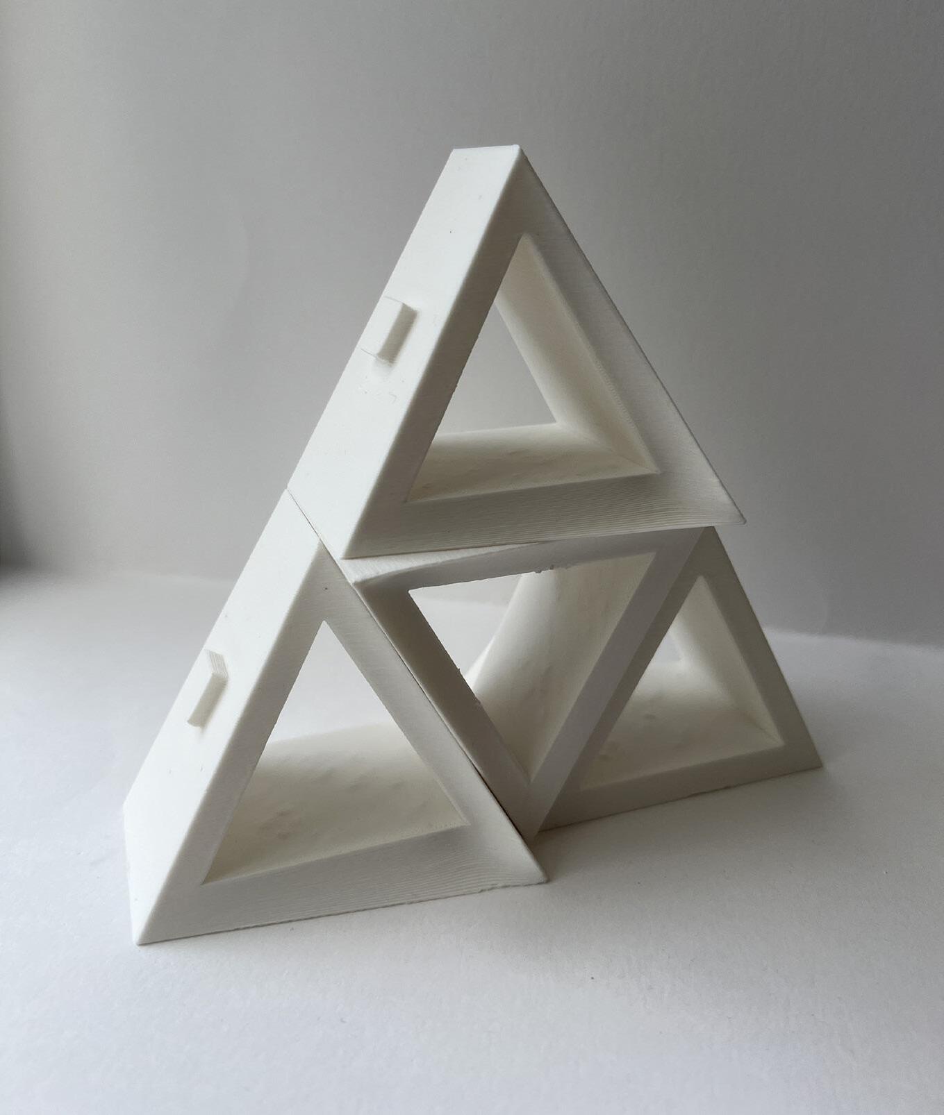
The final print of module 2 applied lessons and tests learned from the previous 2 prints to create a final modular arrangement. Similarly, to create the component, 4 rhino blocks were created and adjusted to make the shapes of the module (figure 34). This design also uses mortise and tenon joints to create the connection between components with a 0.3mm offset
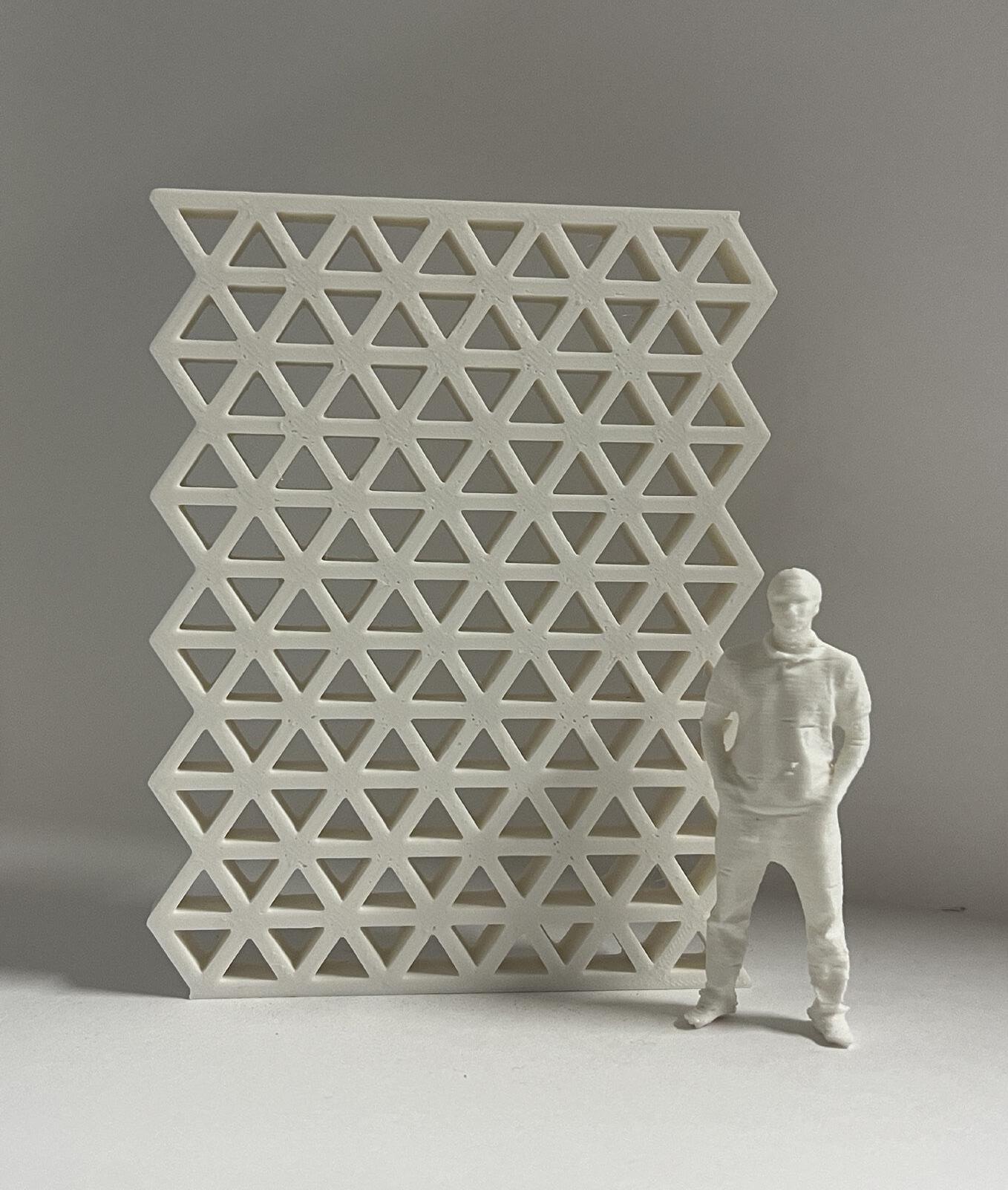
(Figure 35) shows how the component can be repeated creating an arrangement. I applied a 5% gyroid infill to minimize print time (figurer 36 and 37). Looking at the final print, we can see 0.3mm is the safest offset for interlocking components (figure 38). (Figure 39) shows how this design could be used as a permeable wall or shading device at full scale.
