ADVANCED DIGITAL FABRICATION
3D PRINTING AND FABRICATION


3D PRINTING AND FABRICATION



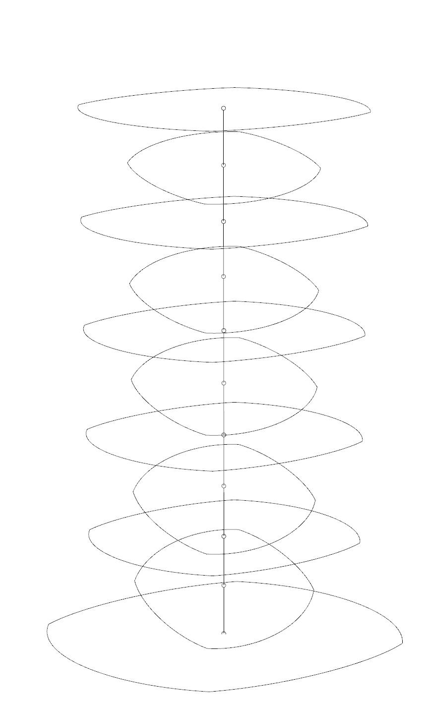
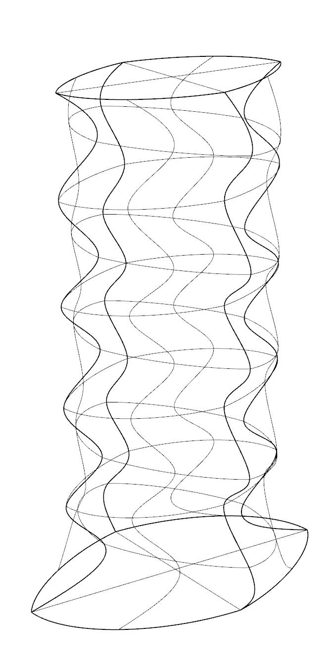
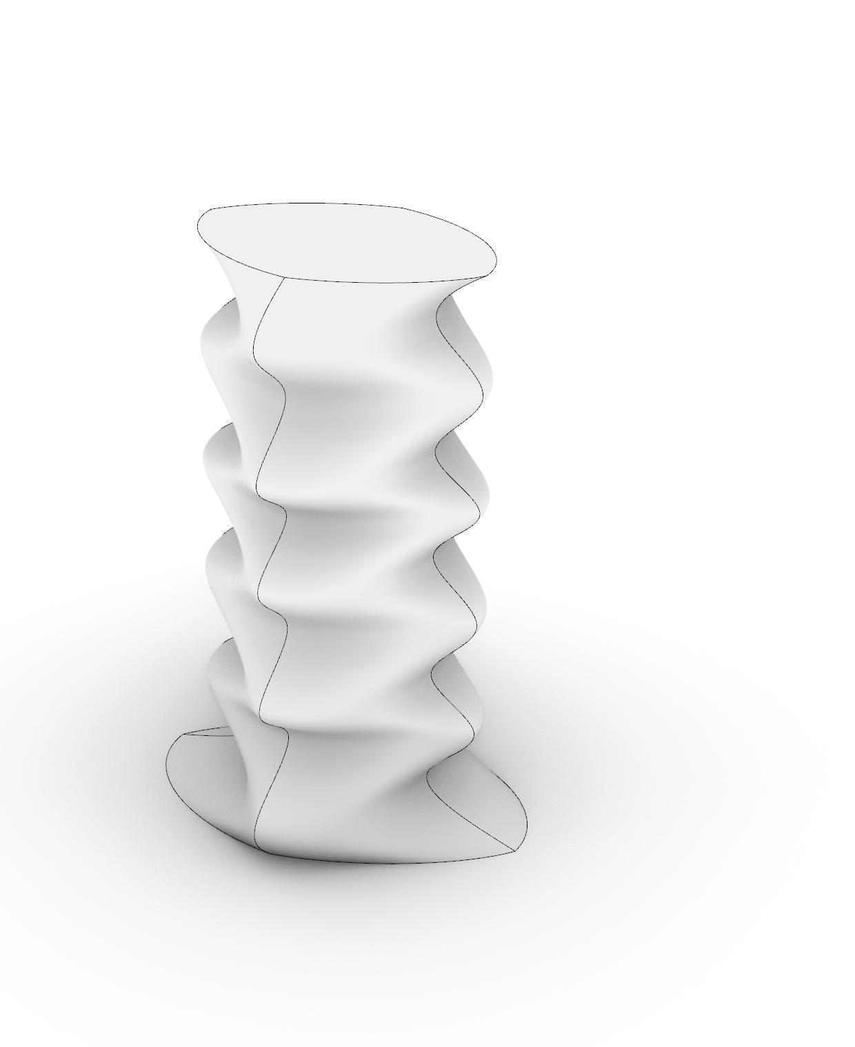
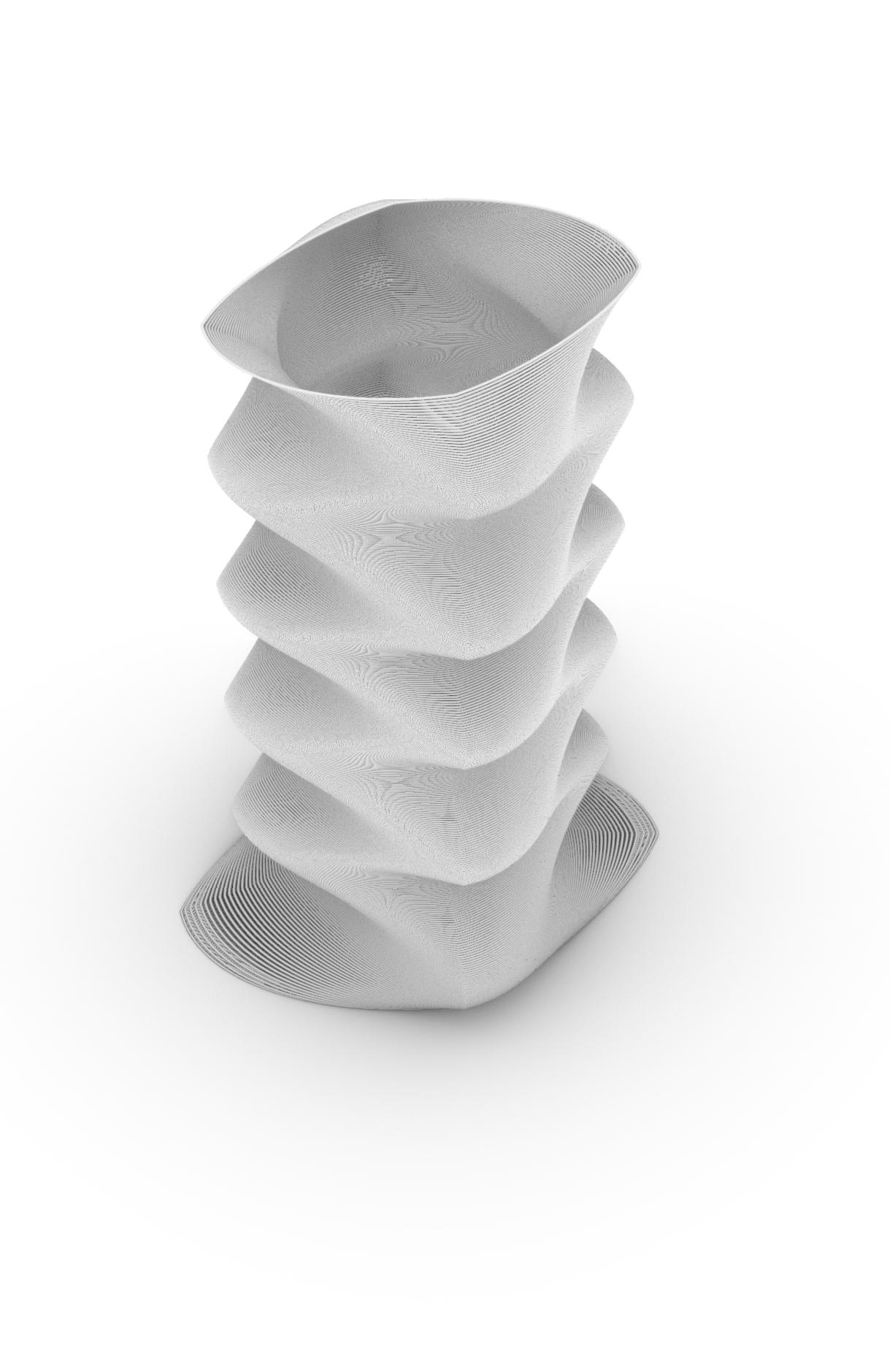
When designing a 3d printed vase I first started by creating an ellipse. I duplicated this shape and lofted them together to create a surface. the image above on the right (fig. 2) shows the wireframe view of the lofted epyps and to the right (fig 3) depicts the same shape capped to create a solid. when 3d printing it is important to cap your models and export a solid stl file into the slicer,
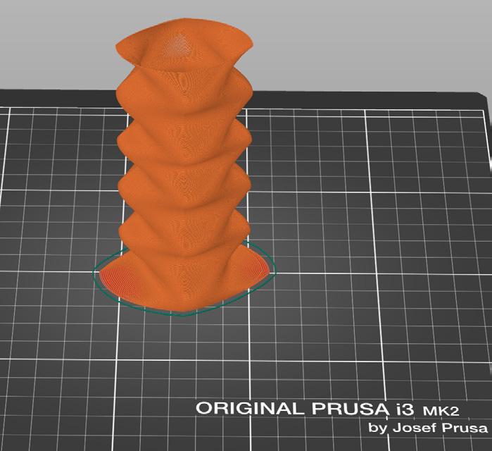
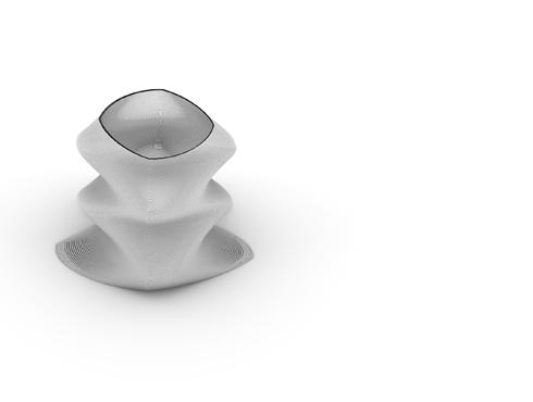
Once I exported the my solid form into the prusa slicer, I then updated the sling program to remove the infill and reduce the exterior shell to a single layer thick. on the far right (fig. 4) shows the final model from the prusa slicer ready to be printed. Some issues I ran into when printing included some layer adheasion issues on the areas with high overhangs.
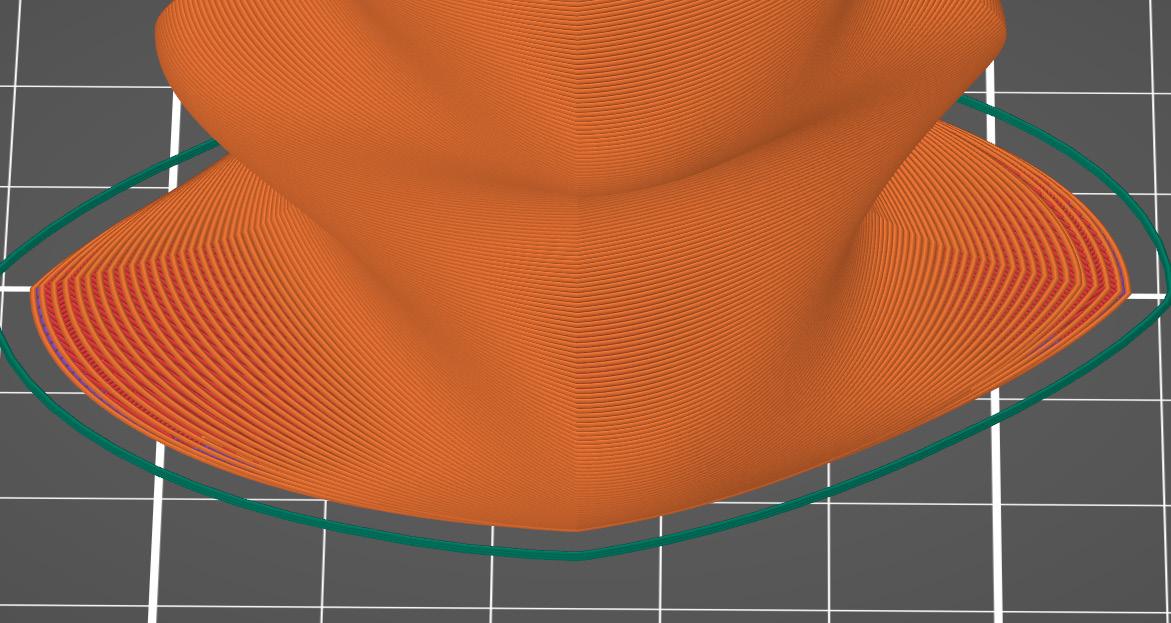
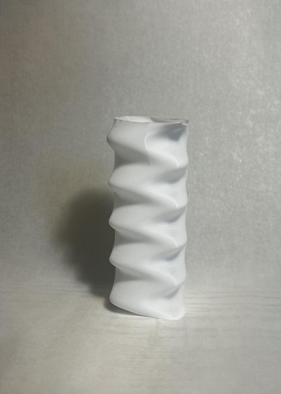
As you can see in the the images on page 5. The areas exsperiencing high over hangs such as the base had gaps between the layers. this created very unstable portions and increased the risk fot the print to fail. to remidy this issue I increased the distance between the ellipses as a way to reduce the over hang angle. this fixed the problem and printed much better.
1_ Arranged ellipses
2_ Wireframe lofted ellipses
3_ Artic view lofted ellipses
4_ Exported tool path from slicer
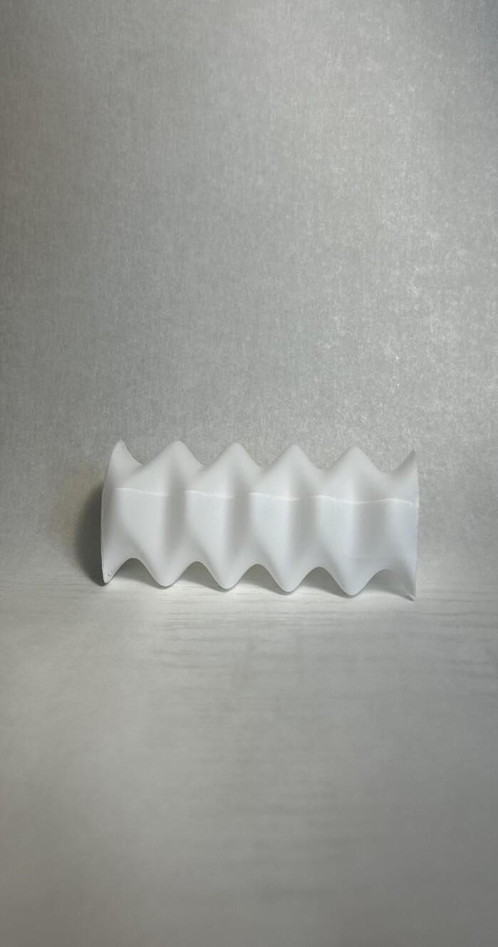
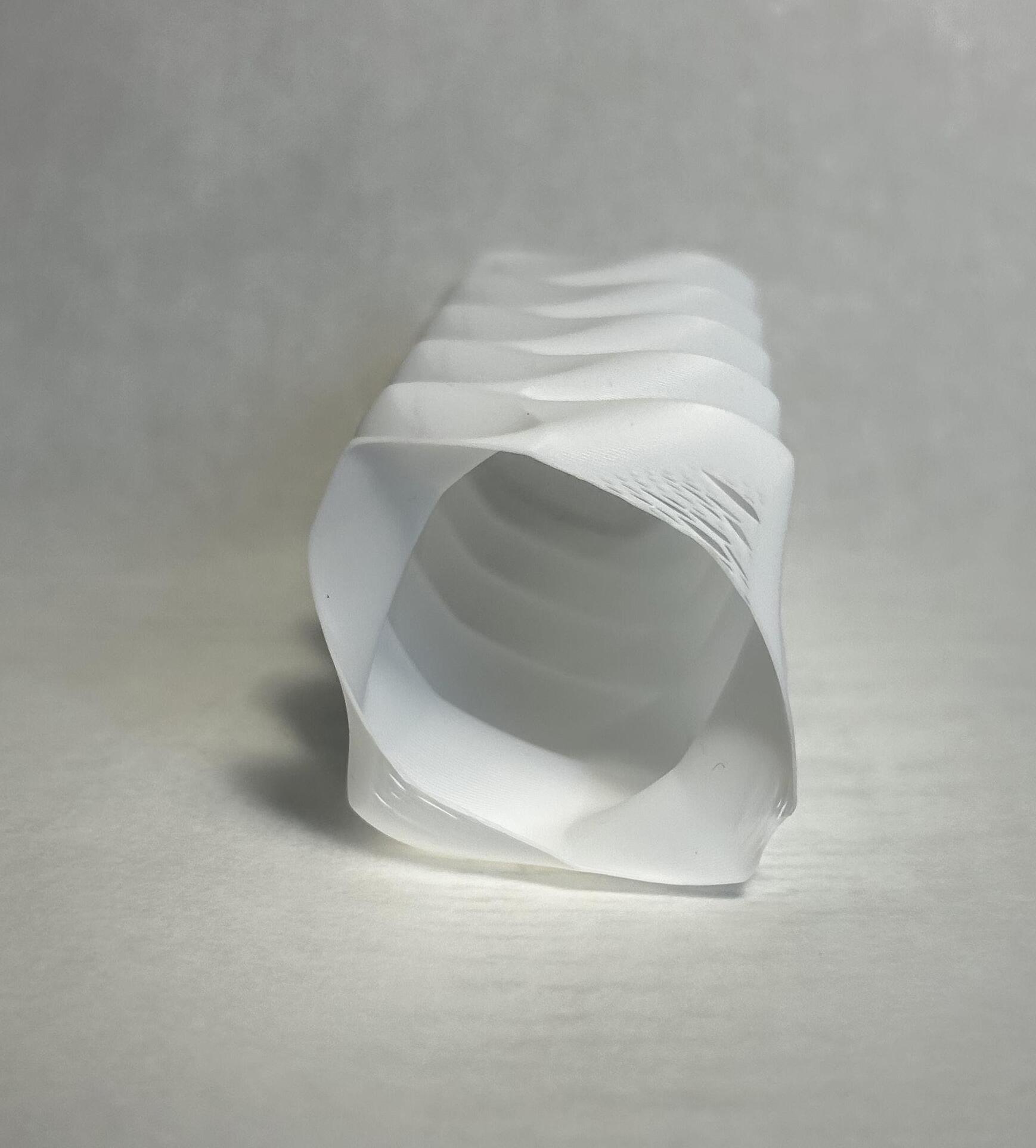
1_ Printed Model
2_ Printed Model
3_ Printed Model
4_ Vase sliced in Prusa
5_ Zoomed in view of layer gaps
DESCRIPTION
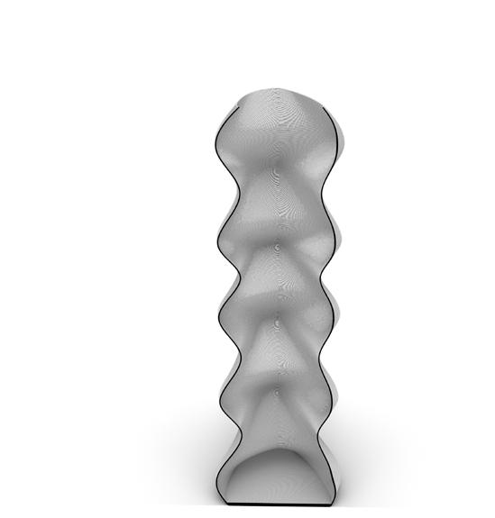
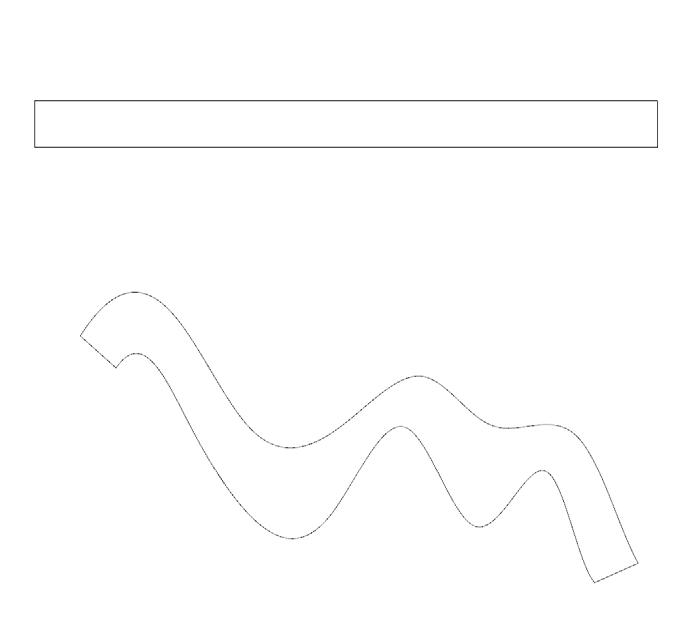
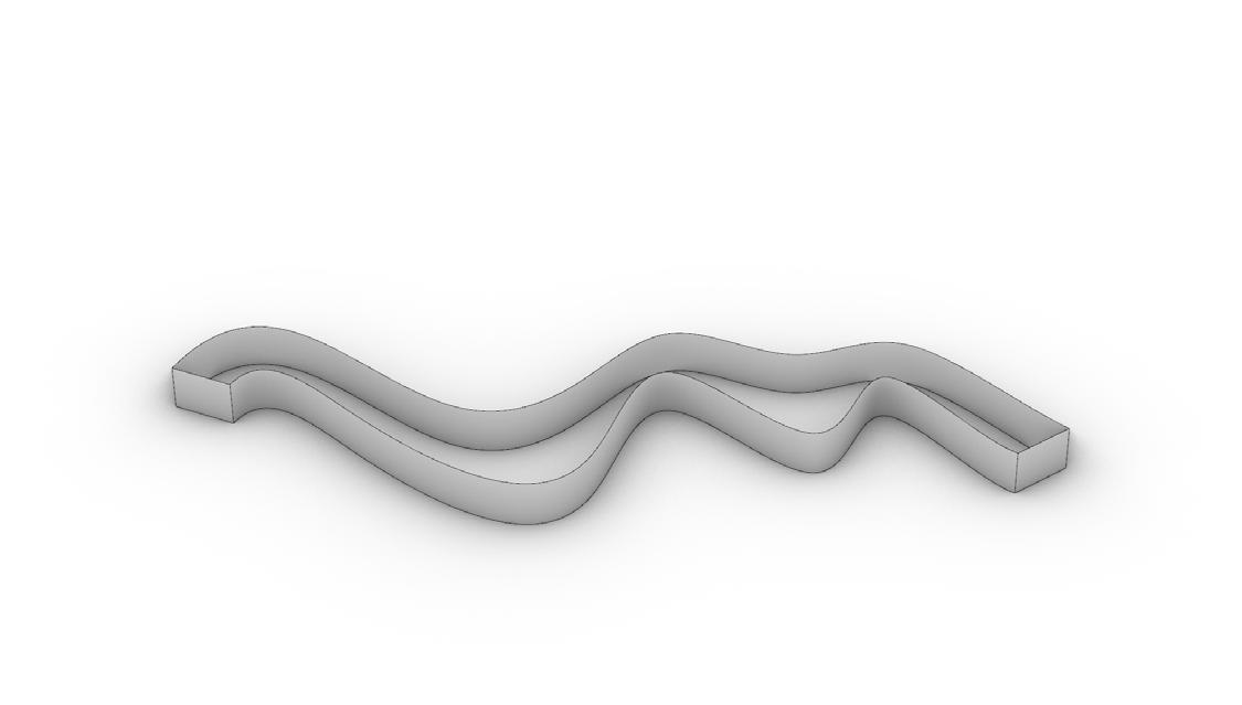
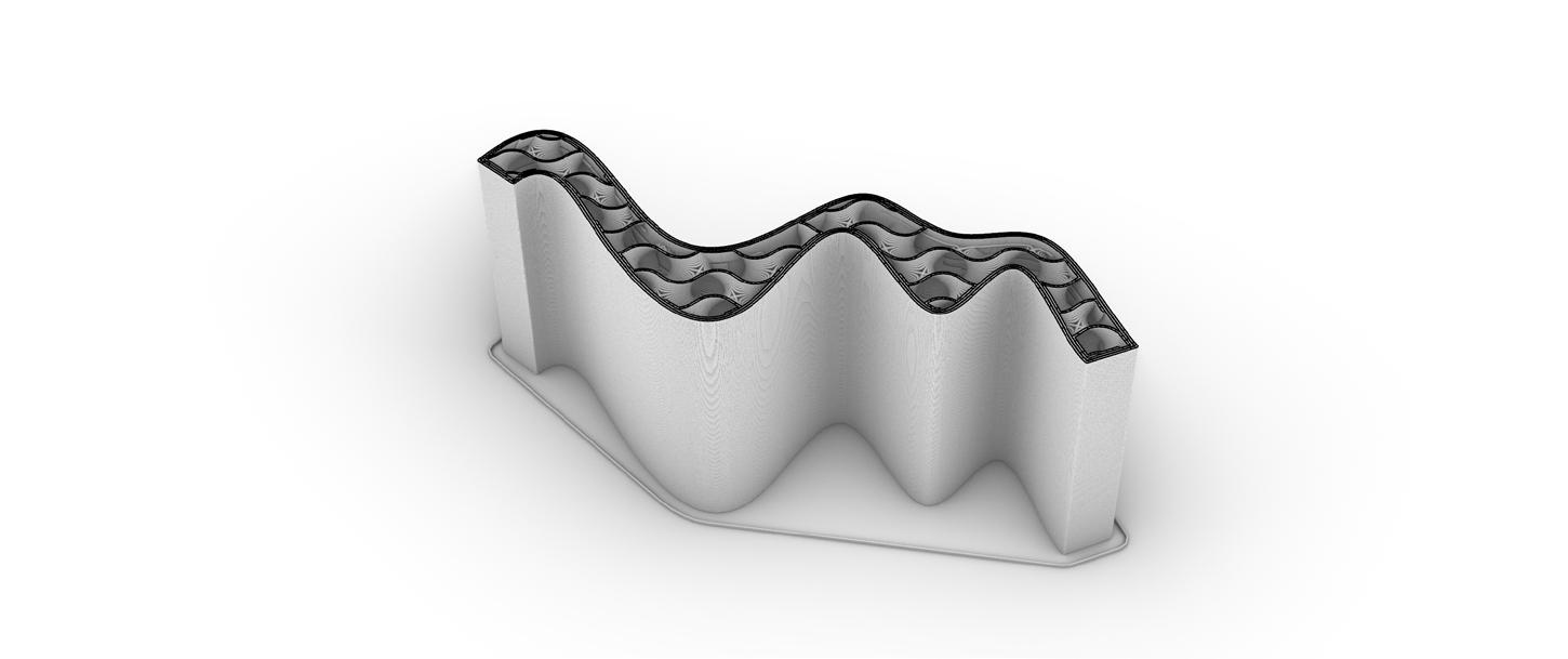
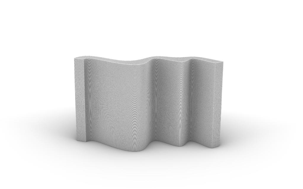
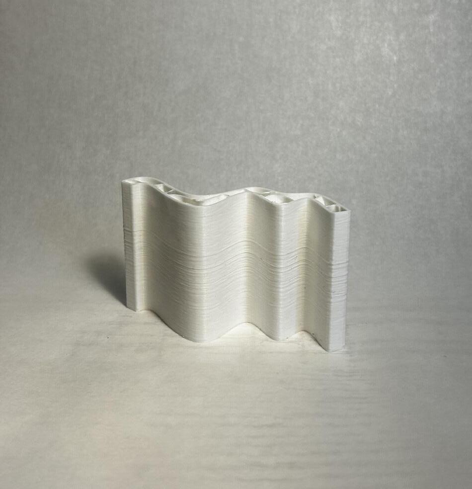
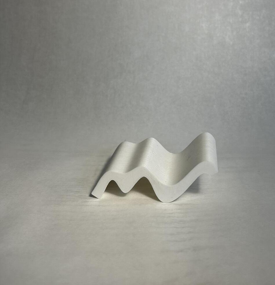
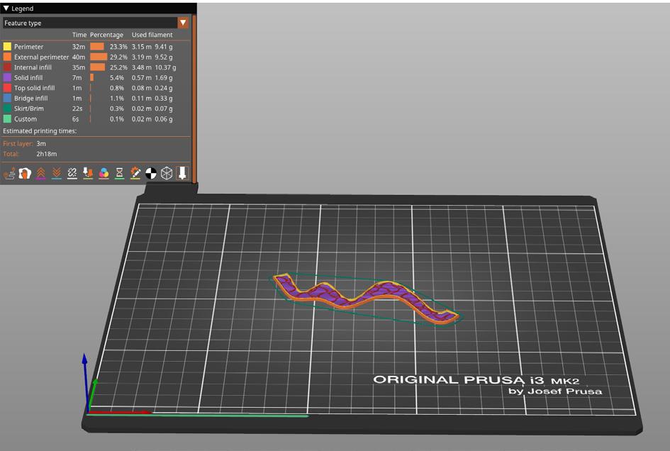
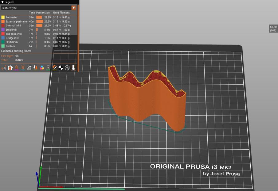
After creating the vase we moved to printing with infill. I designed a wall by manipulating a rectangle to give me the organic shape you can see in the figure above. I then lofted the shape and capped it to create a solid form ready to be exported. In figure 3 to the right you can see the sliced form from Prusa. I decied to print with 10% infill to reduce the print time while still retaing integrity.
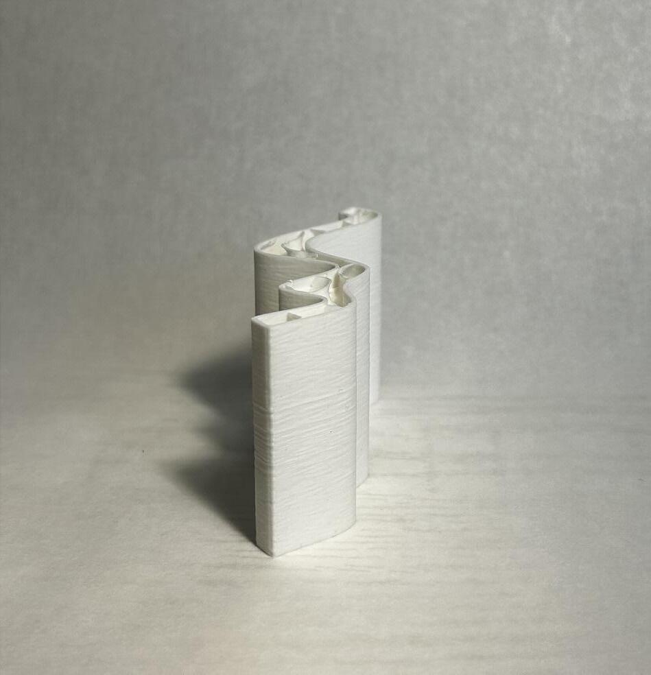
The printing went very well and I didnt run into any issues. However I did decide to stop the print, prior to the top layer being printed. I did this to see how the infill was printing inside the wall. Apon further inspection I found the infill had some gap and wholes. You can clearly see this in figure 5 where there are gaps in almost all of the infill. This is an issue with having to

low of an infill percentage making the gyroid shape to large. his is not a huge issue as the model is still very stiff and didnt effect the printer at all. But I did find it intresting how the infill percentage does have an affect on the quality of the infill as well as the stiffness.
1_ Base line work
2_ Extruded line work
3_ Exported tool path from Prusa
4_ Cut view of infill
5_ Cut view of infill


DESCRIPTION
Just Infill
When attempting to print just infill I did encounter two main issues. One was within the prusa slicer. As you can see in fig. 7 to the right the slicer required a bit of work to get the model to slicer properly. I adjusted the maximum length of infill anchor to be 1mm instead of 8mm. I beleive this issue is due to the fact that when printing infill with an outer shell having a lot of anchor points

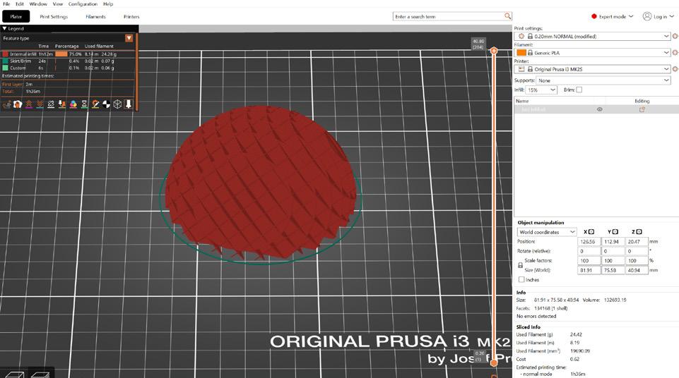
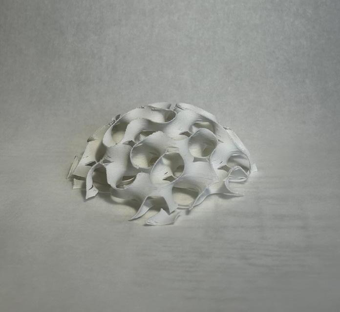
that connect to the shell is very import. we can see this anchors stringing across the exterior of the spear, however these anchors are not essential for this print thus removing them cleaned the slice model. The second issue was print bed adhesion. Given the delicate nature of this shape I ran into issues removing it from the print bed. I ended up breaking the model in
an attempt to remove it. I found it better to allow the print to cool down and use a putty knife to help in removal
1_ Base model from rhino
2_ Exported tool path from Prusa
3_
4_ Cut tool path to show interior of model
5_ Exported tool path from Prusa
6_ Second model sliced in Prusa
7_ Failed model sliced in Prusa
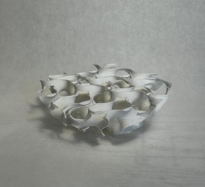

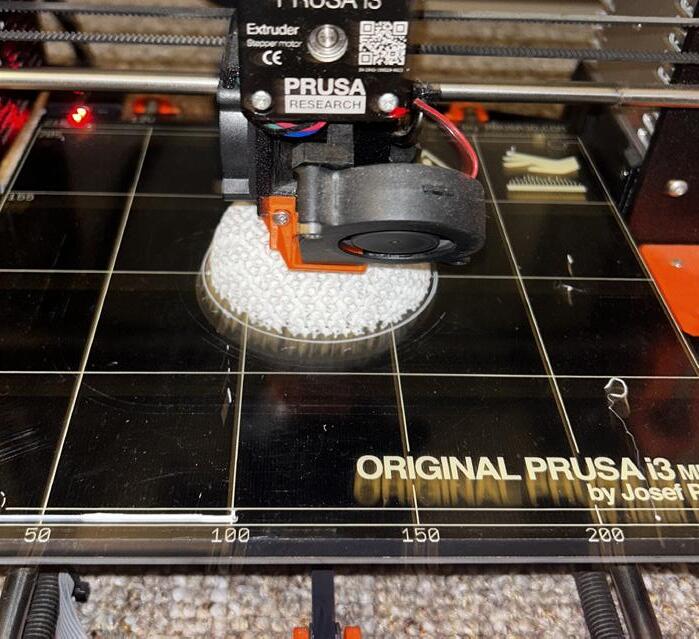
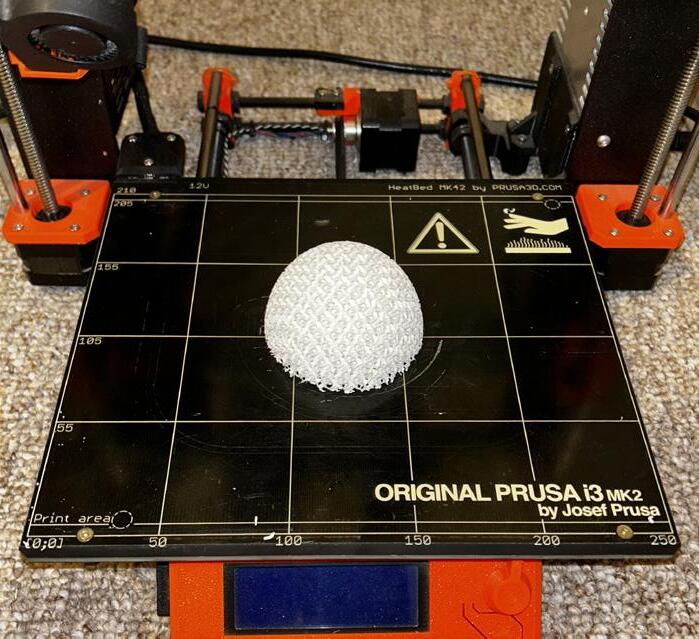
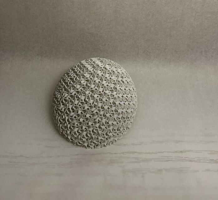
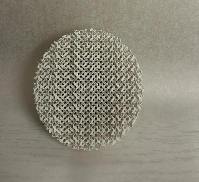
1_ Printed model 5% infill Gyroid
2_ Printed model 10% infill cubic
3_ Printed model 20% infill Gyroid
4_ Printed model 5% infill Gyroid
5_ Printed model 10% infill cubic
6_ Printed model 20% infill Gyroid
7_ 20% infill Gyroid printing
8_ 20% infill Gyroid printing
9_ 20% infill Gyroid printing
DESCRIPTION
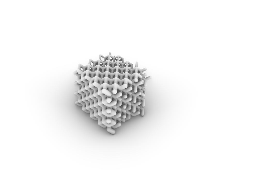
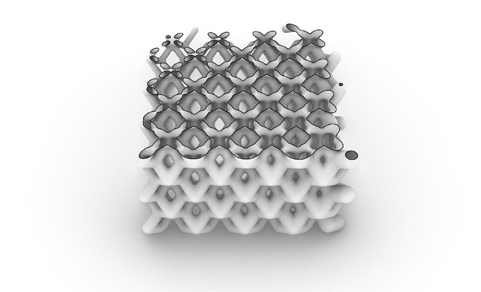
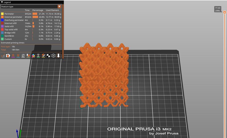
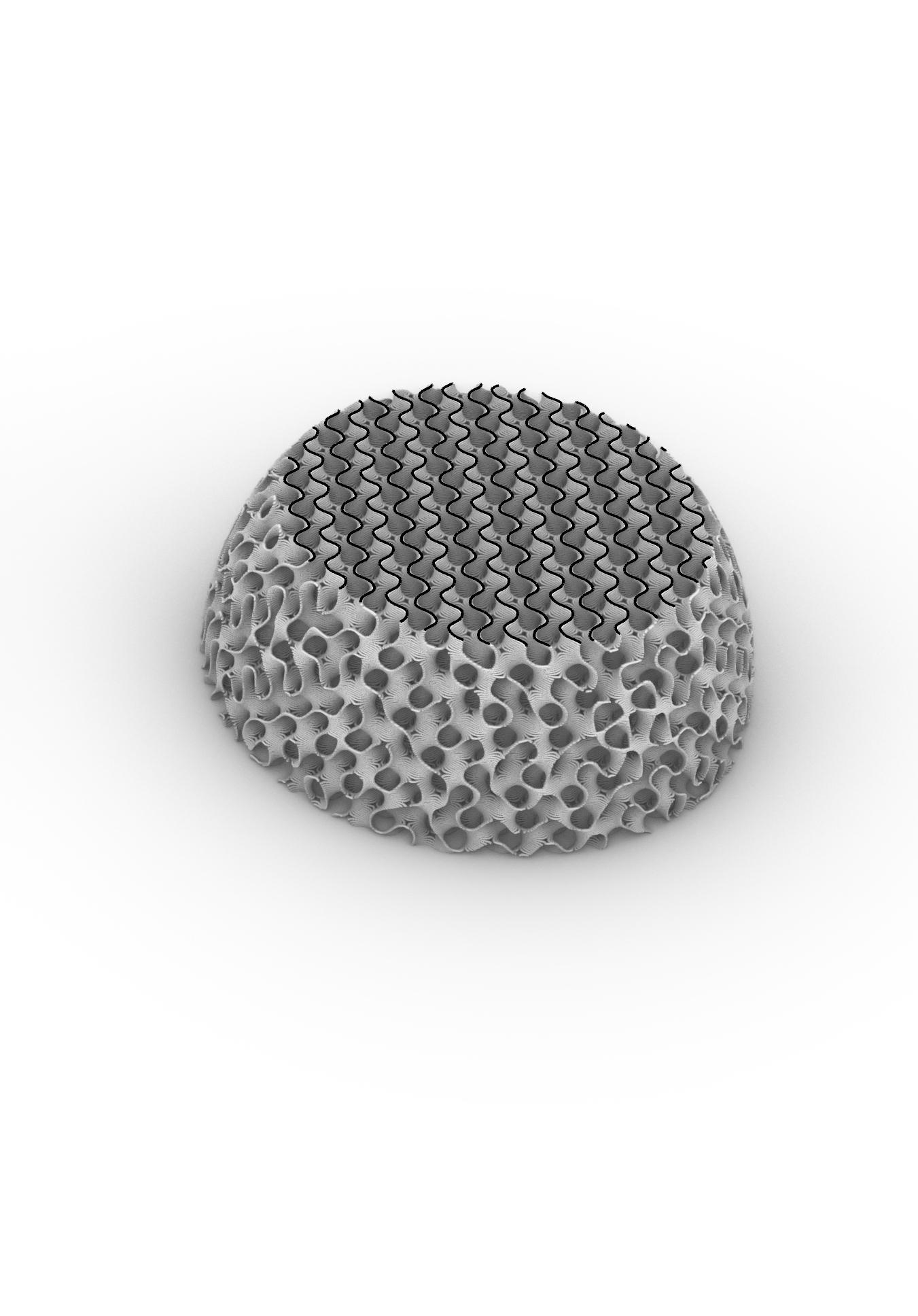
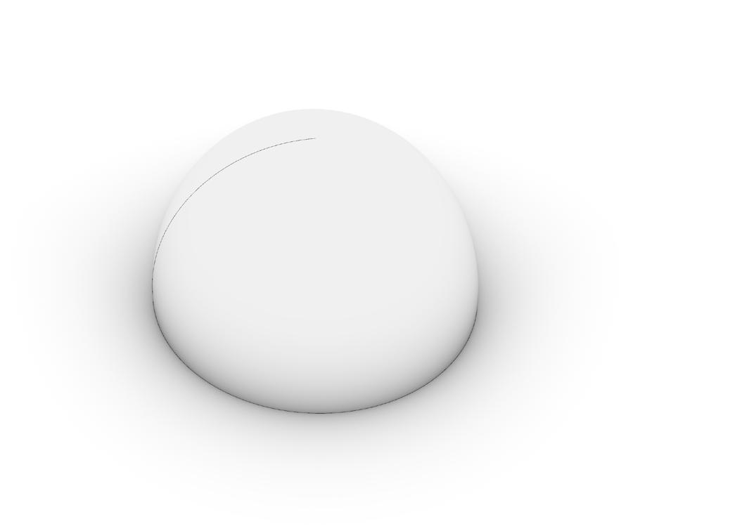
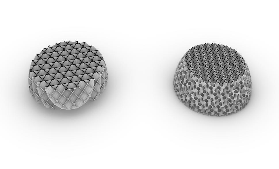
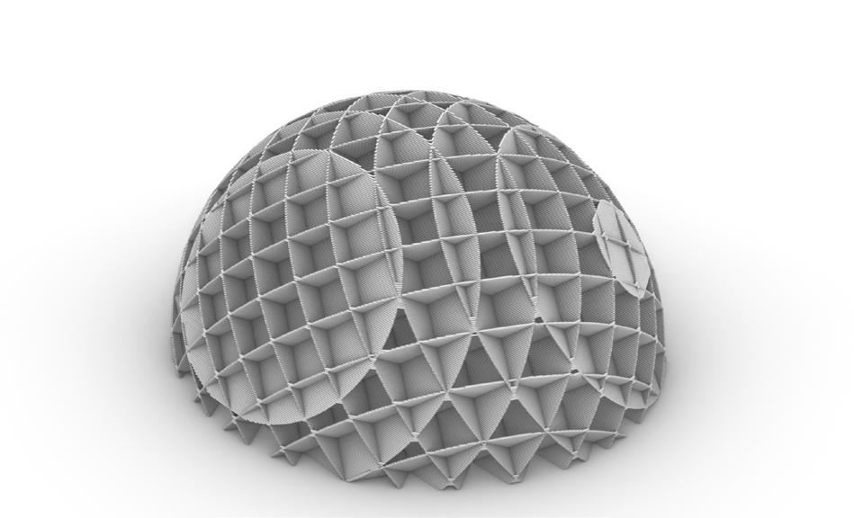
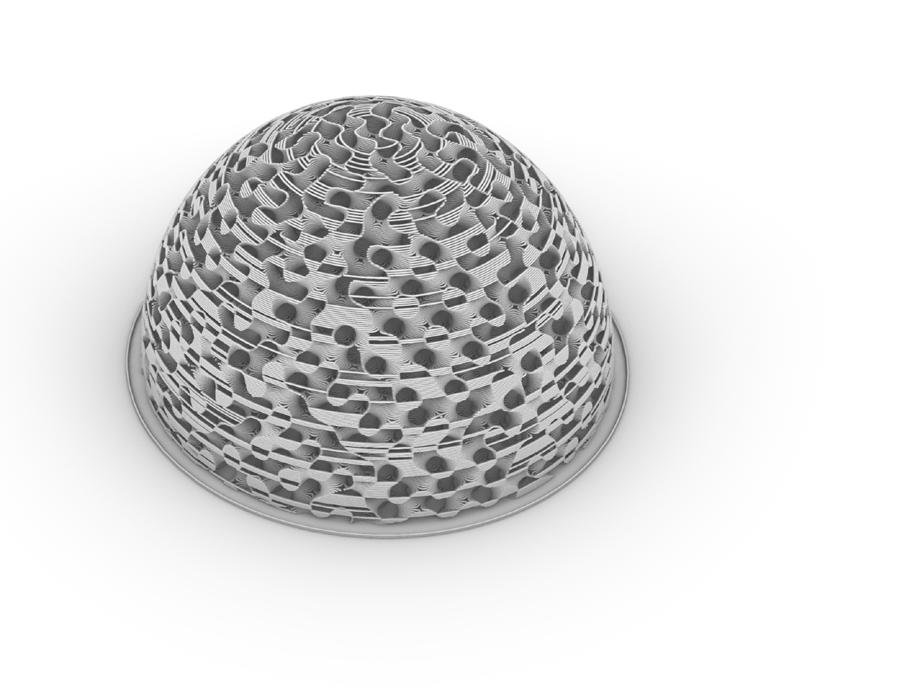
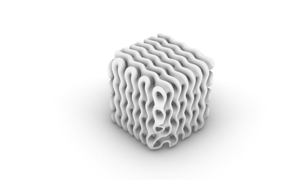
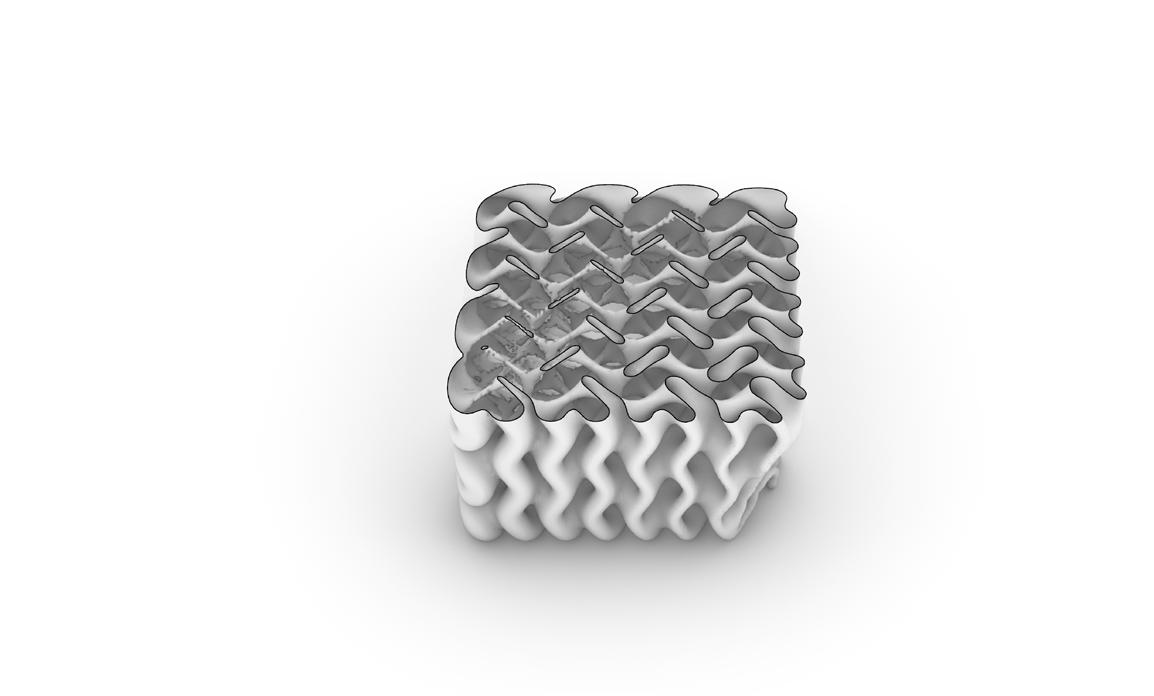
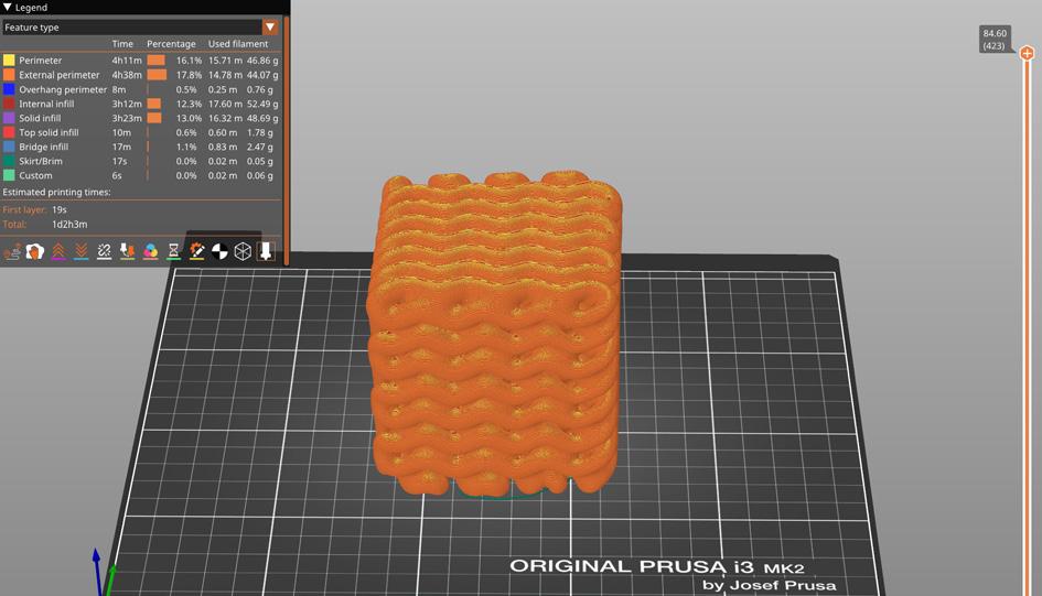
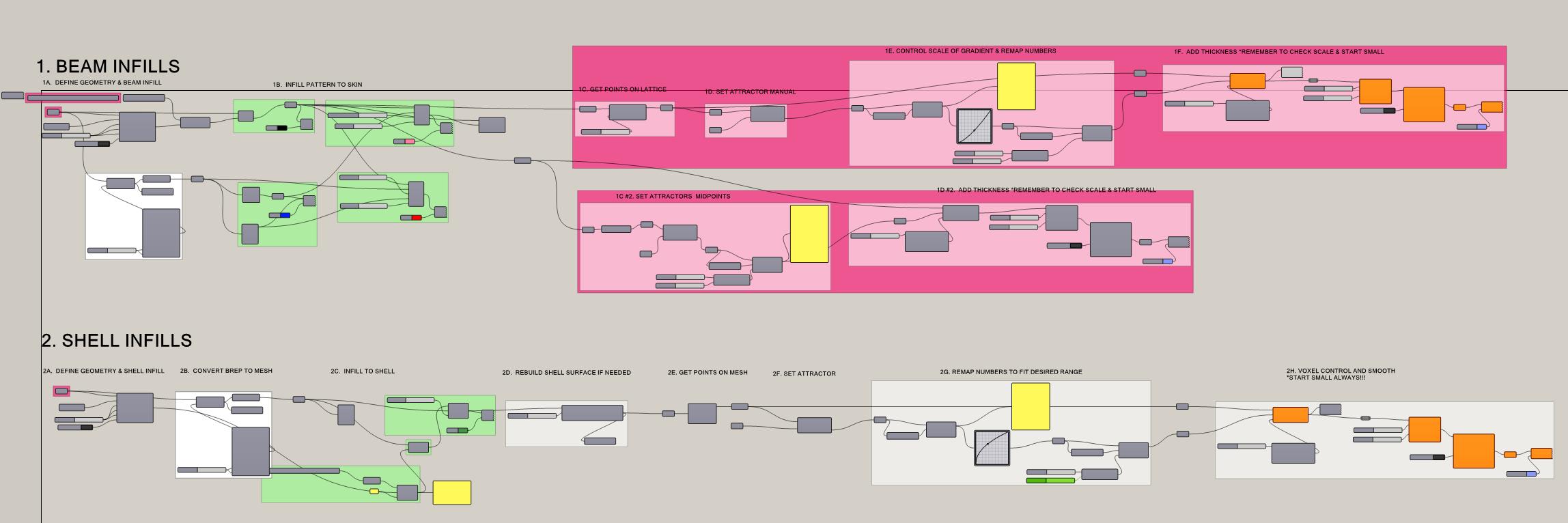
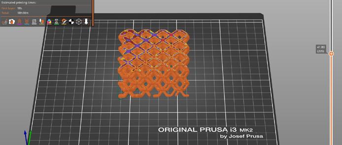
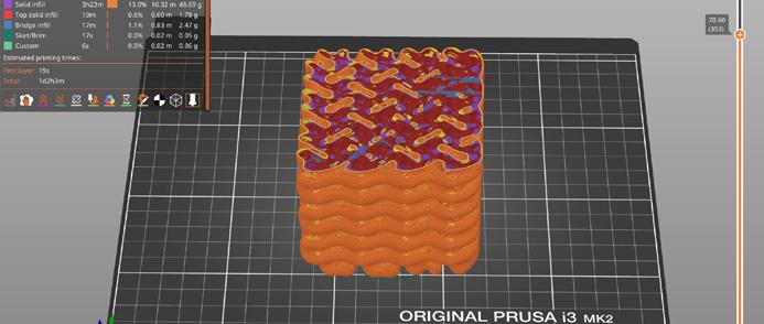
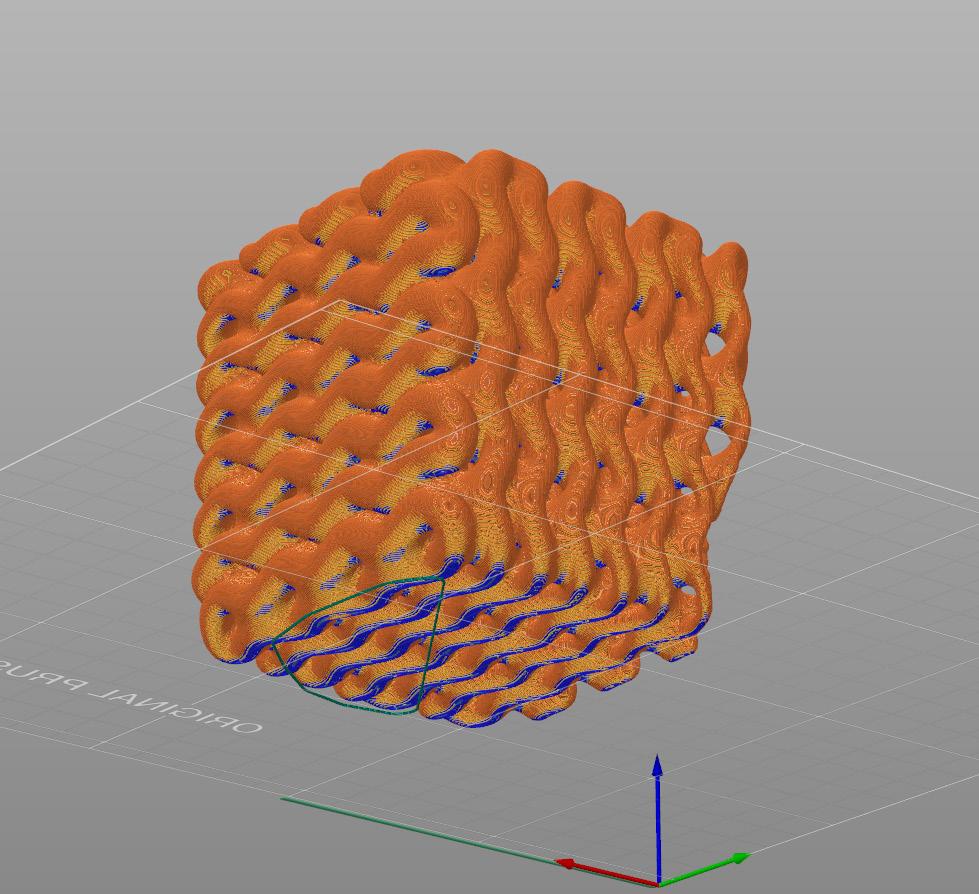
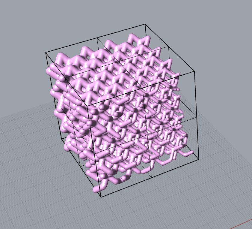
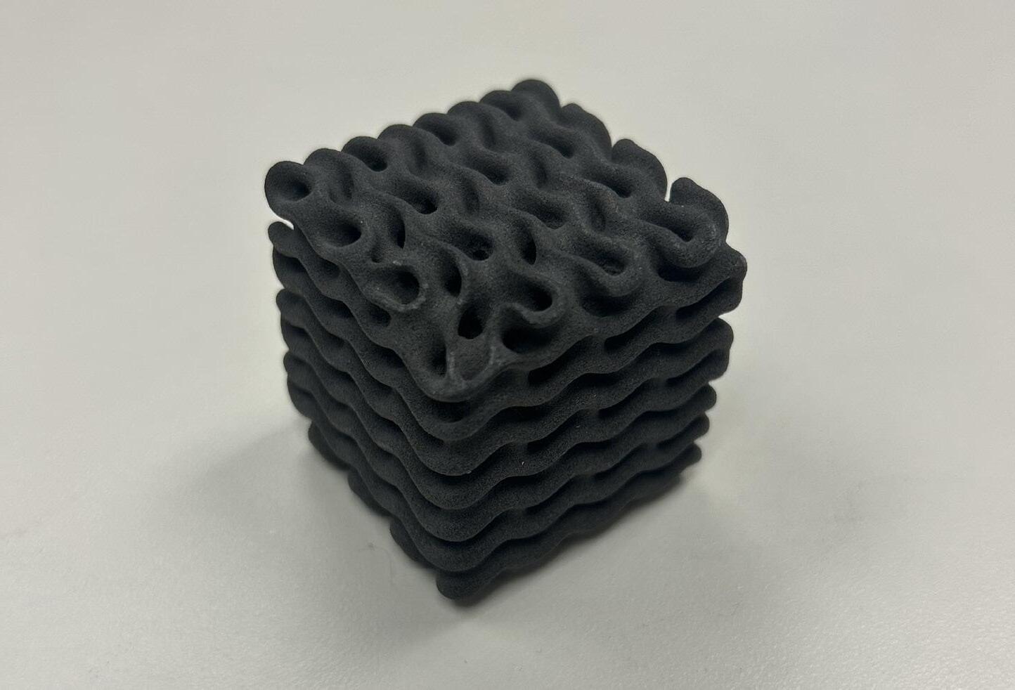
Once completing the infill prints we began exspirimenting with parametric design using grasshopper. This software allows up to create the organic and geometric shapes above. Giving the program parameters that we can manipluate makes it possible to create gradients as seen in figure 4. Using to scripts one for beam infills and one for shell infills
I show I designed the forms above. figure 1 represents the shell infill script running a gyroid shell, while figure 4 is showing the beam infill running dodecahedrom. As you can see from the images on page 11, using the number sliders that control the start and end of the domain allowed me to adjust the gradient or thickness of the beam and shell. This creates very intresting form,
but ones that are impossible to print on a filimant base printer. Given the intricet and detailed interior this would create a print that would take days and use supports that would be impossible to remove. The only way to print these shapes would be to use a formlabs sls printer. These are capable of printer far more detailed parts with much less support material if any at all.
1_
2_
3_
4_
5_
6_
4
DESCRIPTION
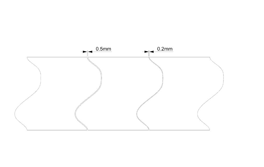
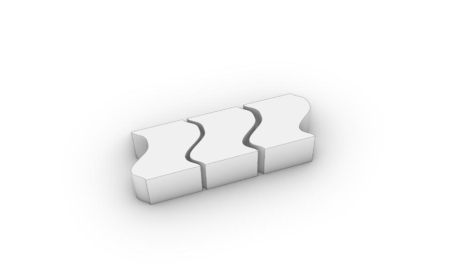
To start module 2 we began our exploration into tolerances. Tolerance is the diffrence in size required to allow two pieces to fit together. What I learned from the prints above is a tolerance between .2mm and .3mm works the best for the prusa printers. When printing a interlocking part having a larger tolerance helps allow the parts to lock together as seen in figure 6.
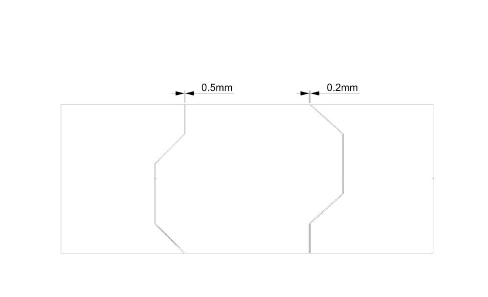
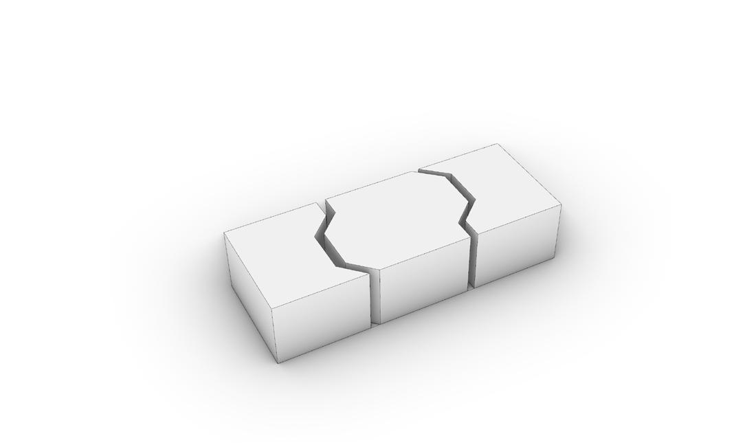
In figures one and two I explored how adding tolerance would effect the overall shape while figure three explored a more funtional interlocking join. What I found was the .5mm tolerance was most effetive in the interlocking model as the complicated geometry meant that any imperfection would cause them to not fit, thus having a larger tolerance accounted for this. The

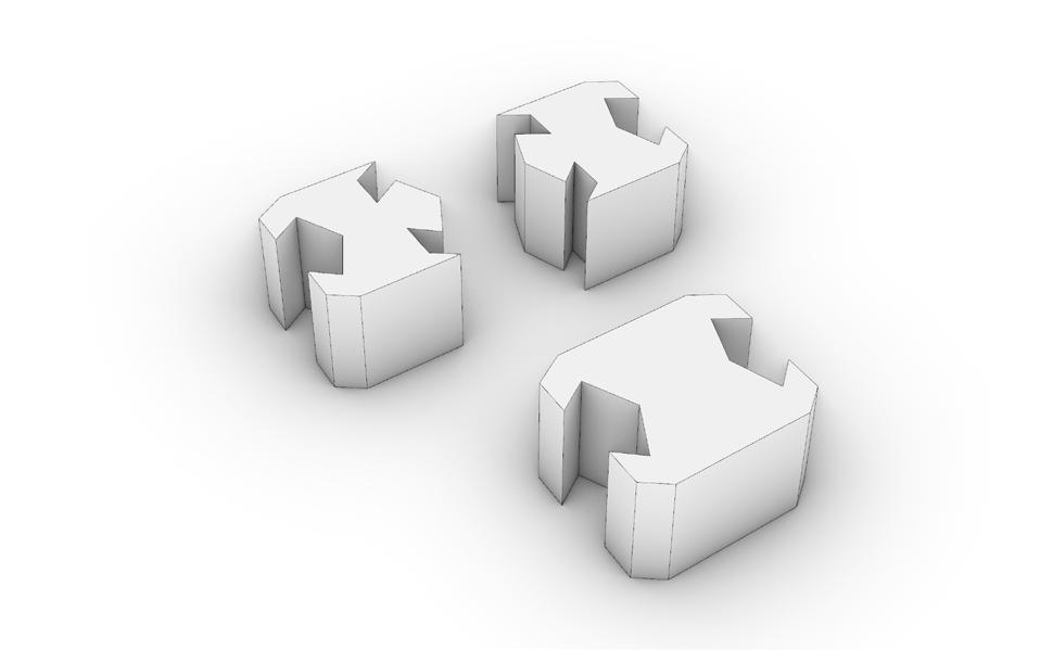
1mm gap however was too much and made the two very loose fitting. Figure one and two showed me that the gaps made for tolerance are really negible and do not effectthe overall shape of the model as long as you keep the tolerances tight and to a minimum.
1_ Linework of organic tolerance model
2_Linework of geometric tolernace model
3_ Linework of interlocking tolerance model
4_ Organic tolerance Rhino model
5_ Geometric Tolerance Rhino model
6_ Interlocking tolerance Rhino model
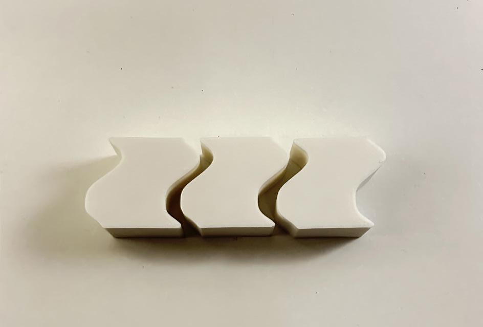

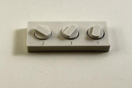
These are the actual printed models where you can see how the tolerance effects the prints. In figure two you can see the diffrence between .2mm on the right and .5mm on the left. You can barley see the joint on the top right however it is very pronounced on the left. this occured in all of the prints, which showed me that the .2mm gap was optimal for prints of this size and scale. One thing to look out for when
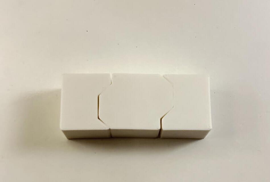
printing with tolerances is scaling. You want to make sure that no matter size object you are printing that the tolerances stay between .2mm -.5mm. When scaling either in the slicer or your 3d modeling software, ensure that your tolerances do not scale and make the gap larger than it should be.


DESCRIPTION
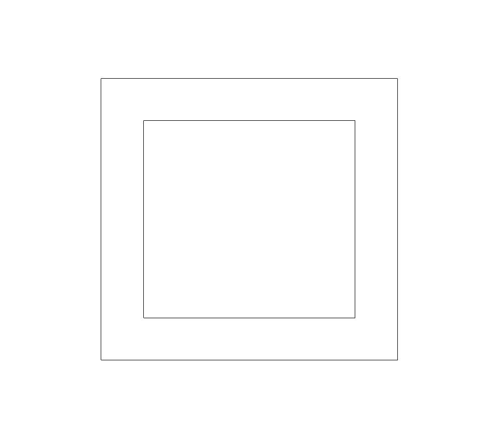
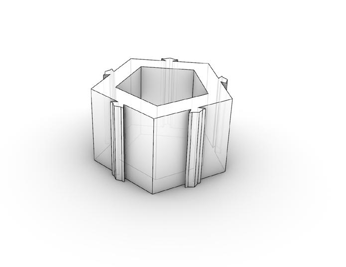
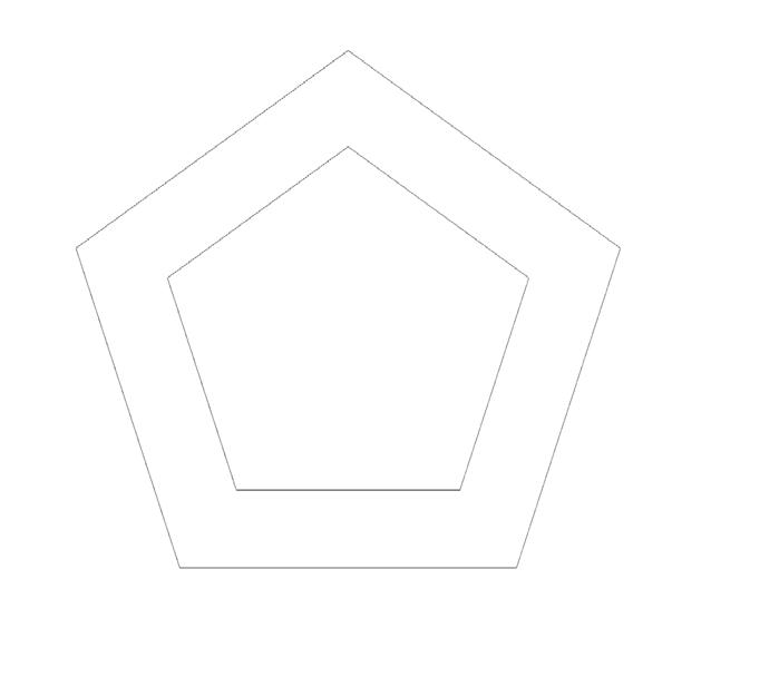
We were tasked with creating a module that can be aggregated togther to form a wall or other larger object. I wanted to create a space divider that could be placed in the middle of an office to seperate a larger space while also being aesthetically pleasing and offer storage options. My first idea was to use a pentagon as seen above with interlocking key shaped extrusions
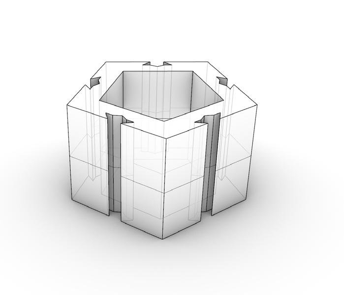


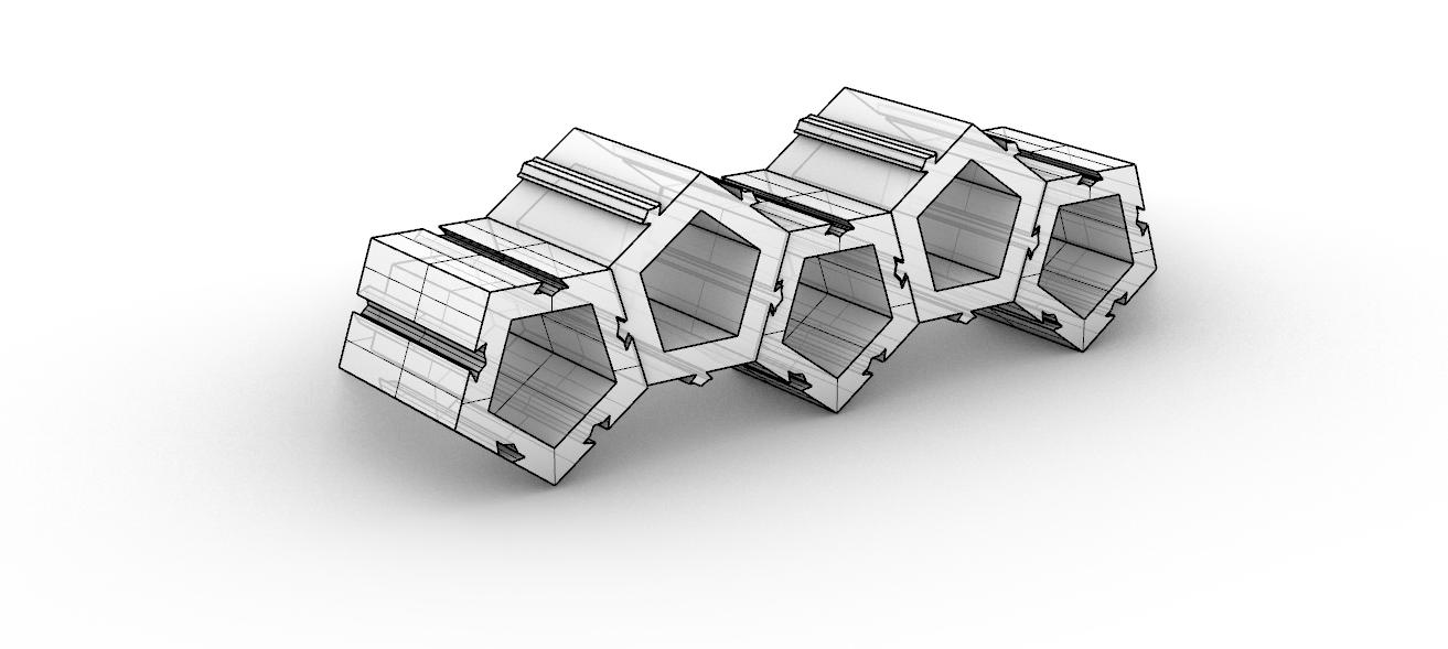
to hold everything together. While a good place to start the irregular shape made the piece difficult to arrange leaving odd shapes within the aggregation. Along with this having connection points on all sides made the edge condition look unfinished, so I began to move to my next idea.
1_ Diagramming constrcution of module
2_ Diagramming constrcution of module
3_ Diagramming constrcution of module
4_ Diagramming constrcution of module
5_ 3d model in Rhino
6_
7_
DESCRIPTION
First Aggregation Model
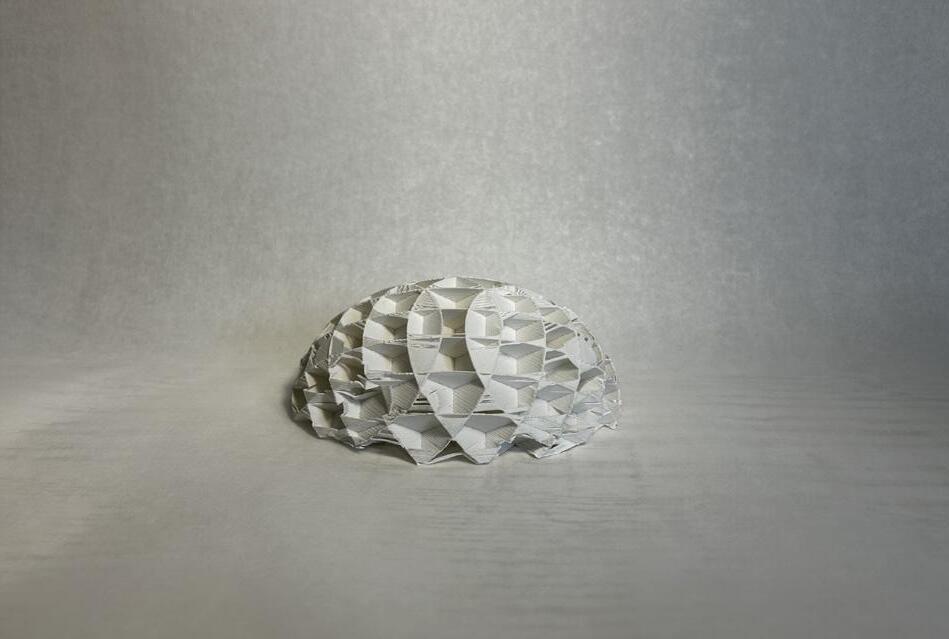
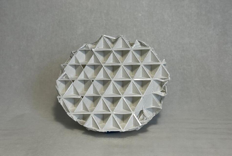
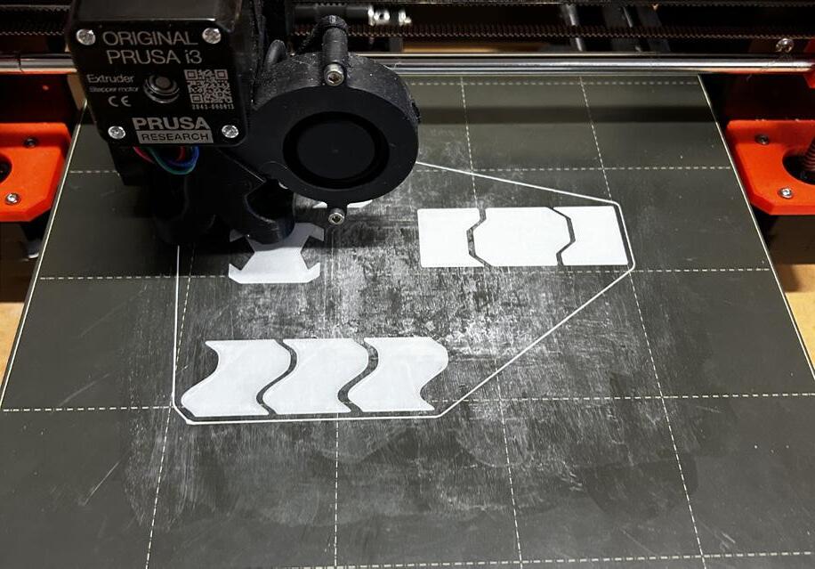
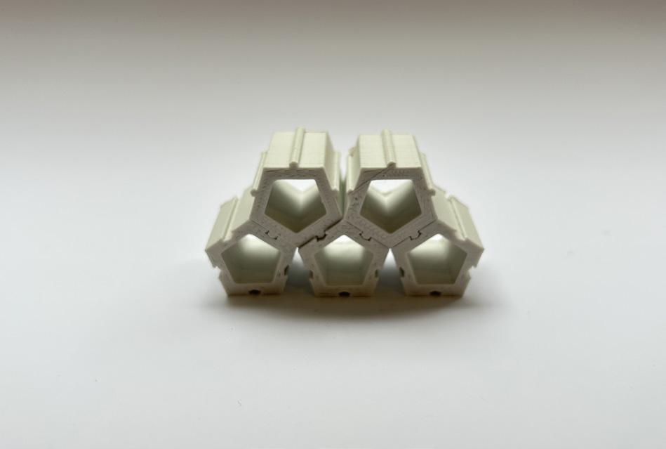
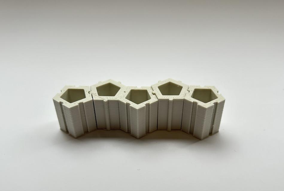
As you can see from the images above, the pieces I created fit well together however struggle to be stacked vertically. The gaps that formed in between modules become more apparent the higher you stack which was not desirable. Along with this the orientation of the pieces was essential to create the desired form as the shape is asymmetrical. I wanted to create a
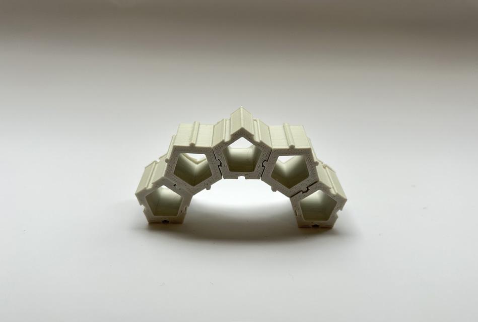

form that could be universally aggregated without gaps or need to worry about orientation. This would make construction and assembly much easier and create a better boundry. For these reasons I decided to look into other options. This exsperimentation was key to figure out the key apsects to my design.
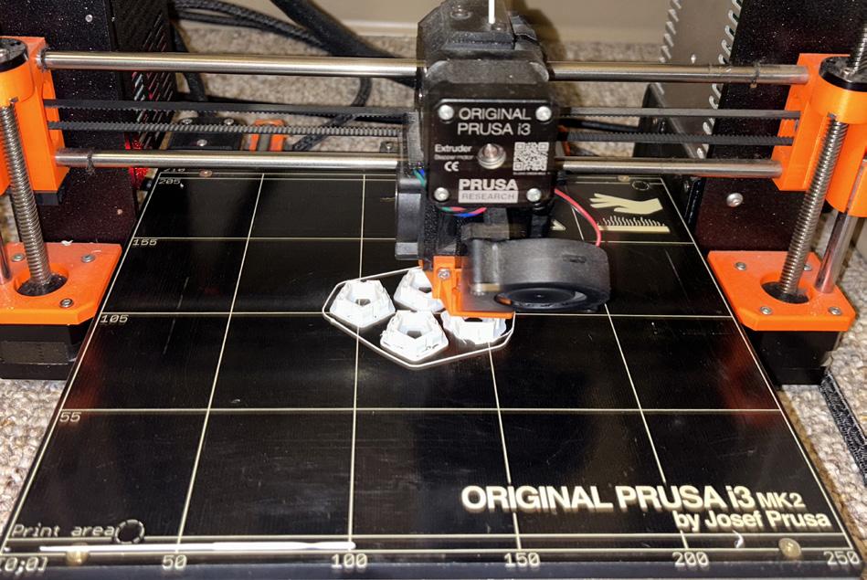
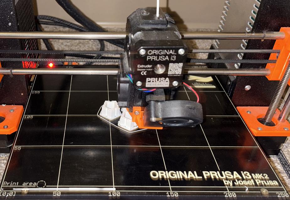
1_ 3d printed module version 1
2_ 3d printed module version 1
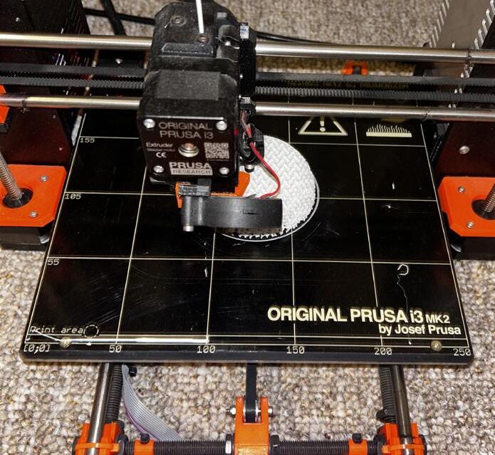
3_ Prusa i3 MK2 printer in progress
4_ 3d printed module version 1
5_ 3d printed module version 1
6_ Prusa i3 MK2 printer in progress
DESCRIPTION
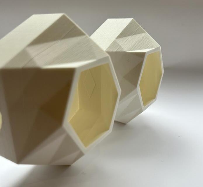
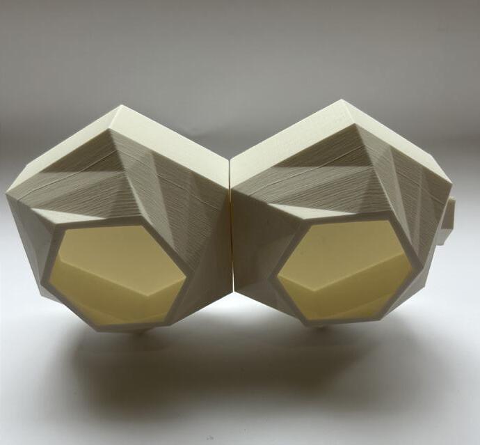
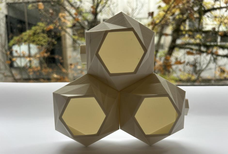
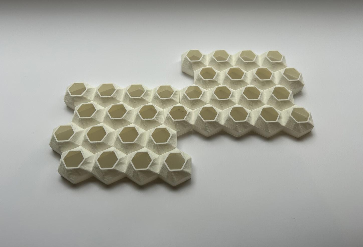
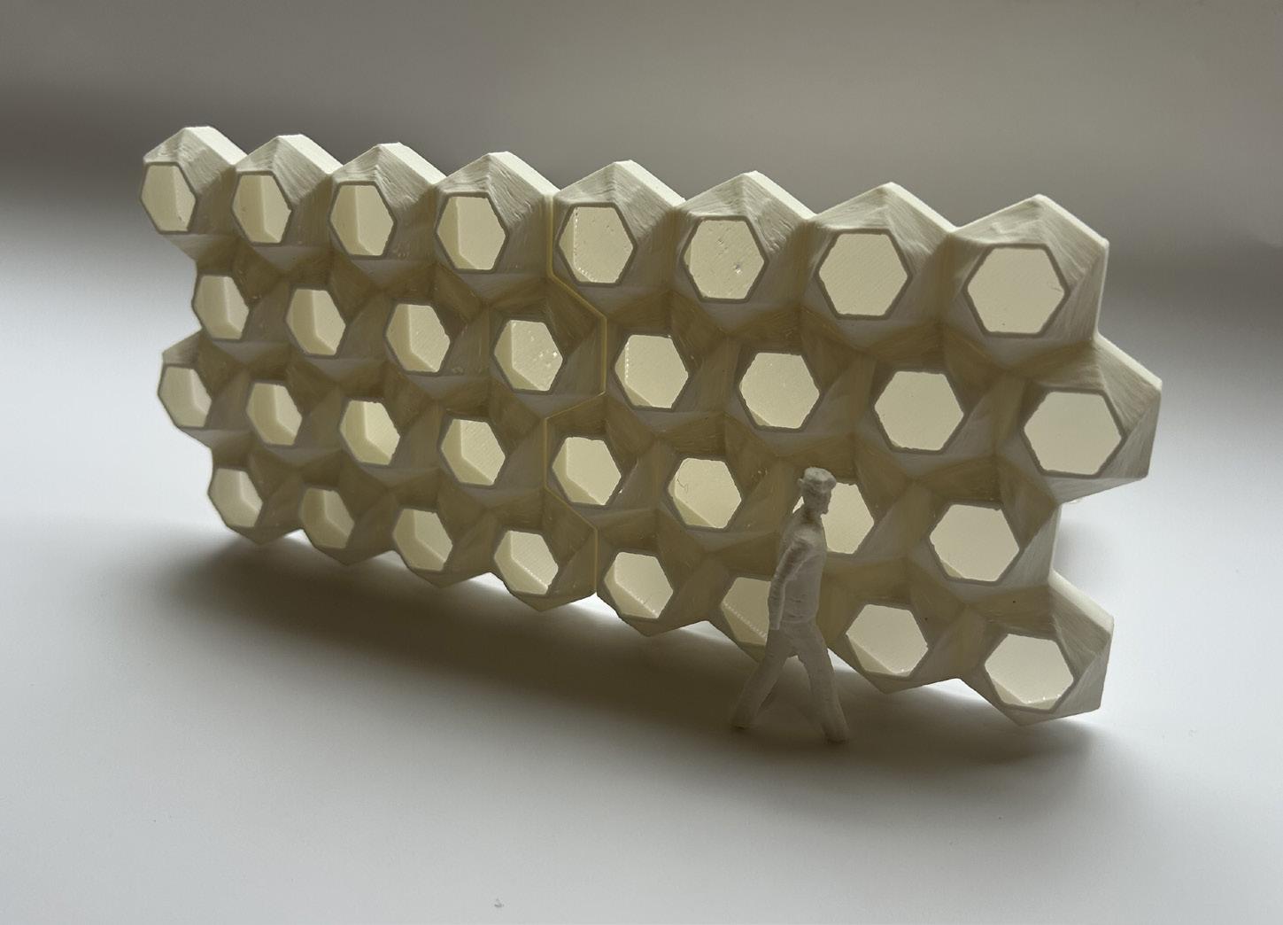
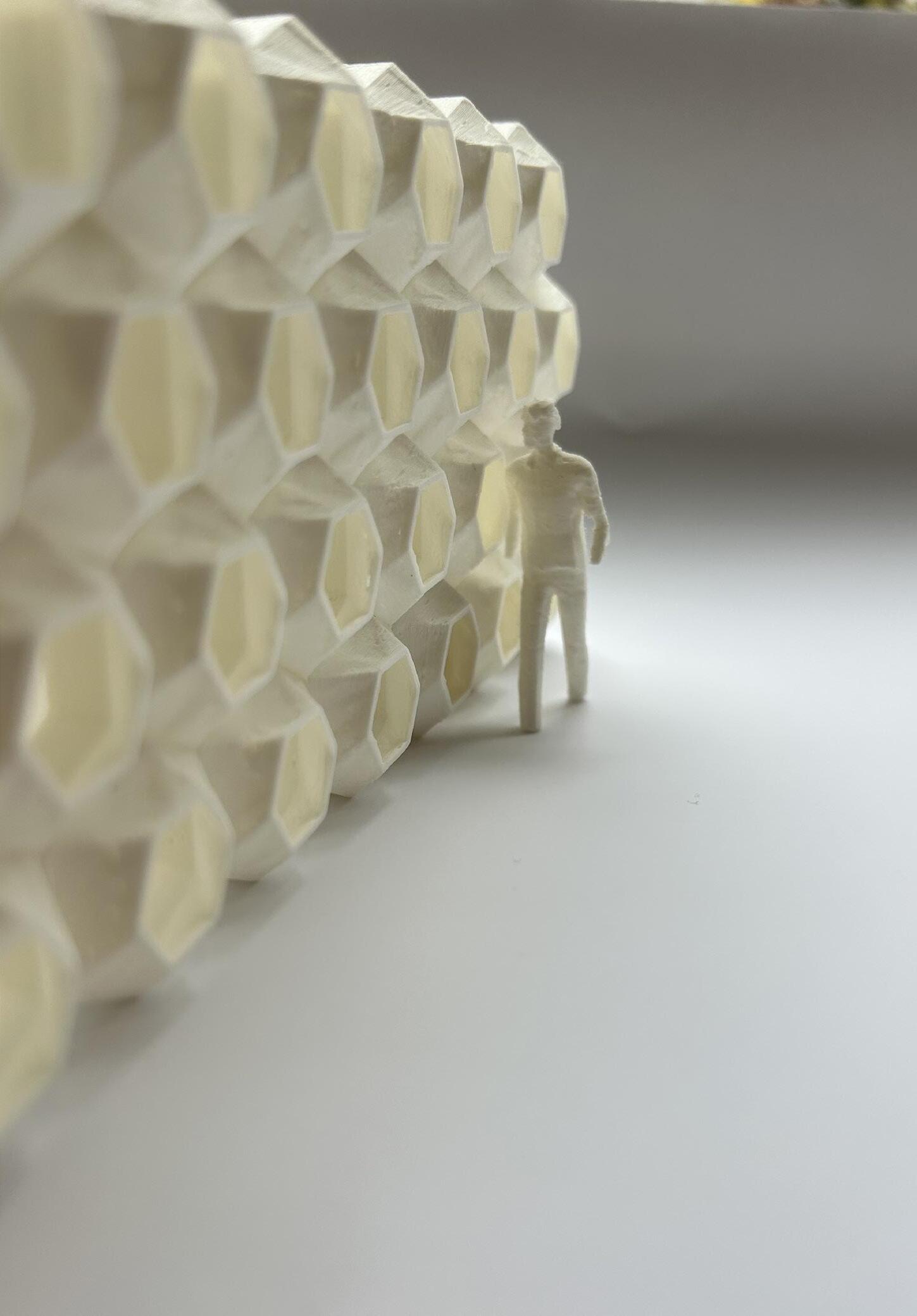
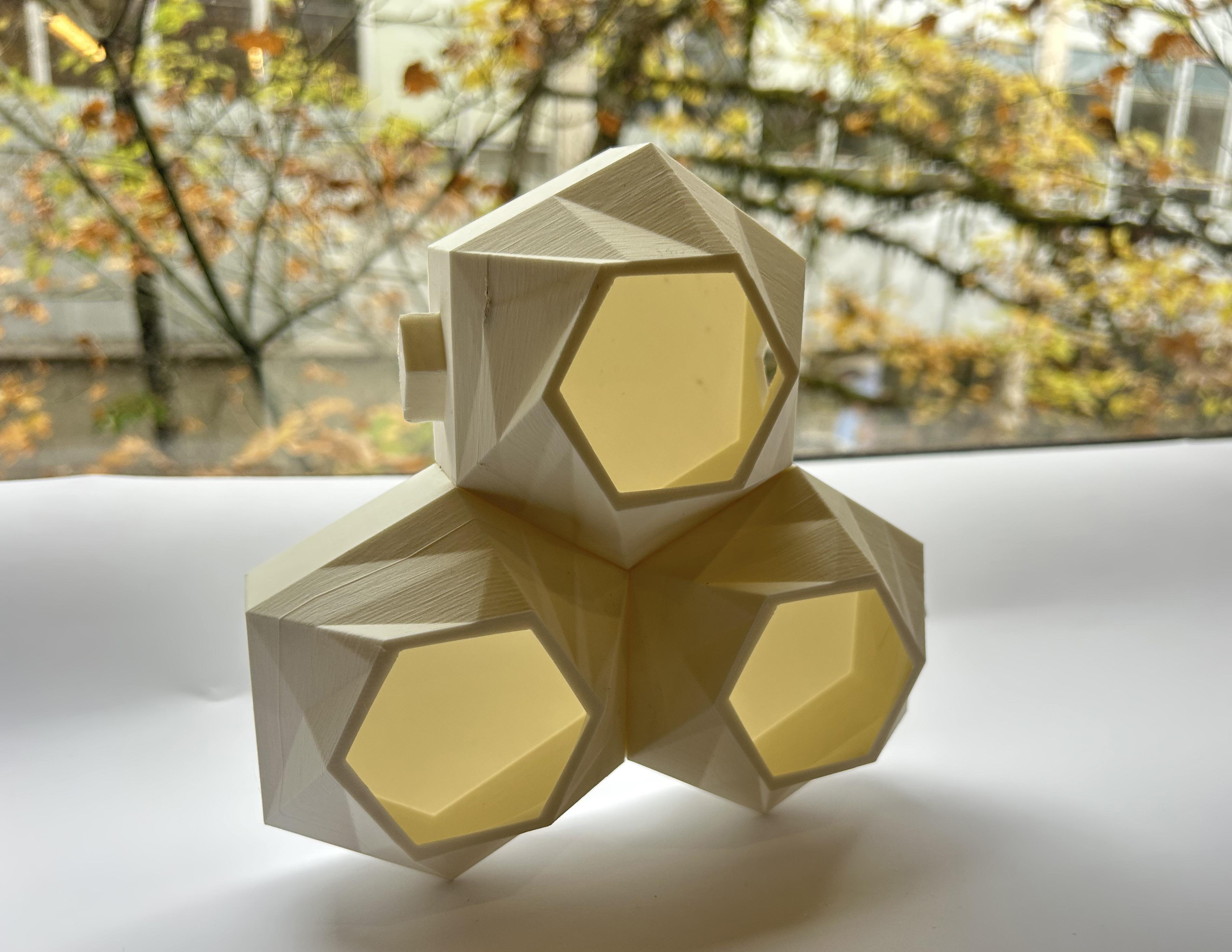
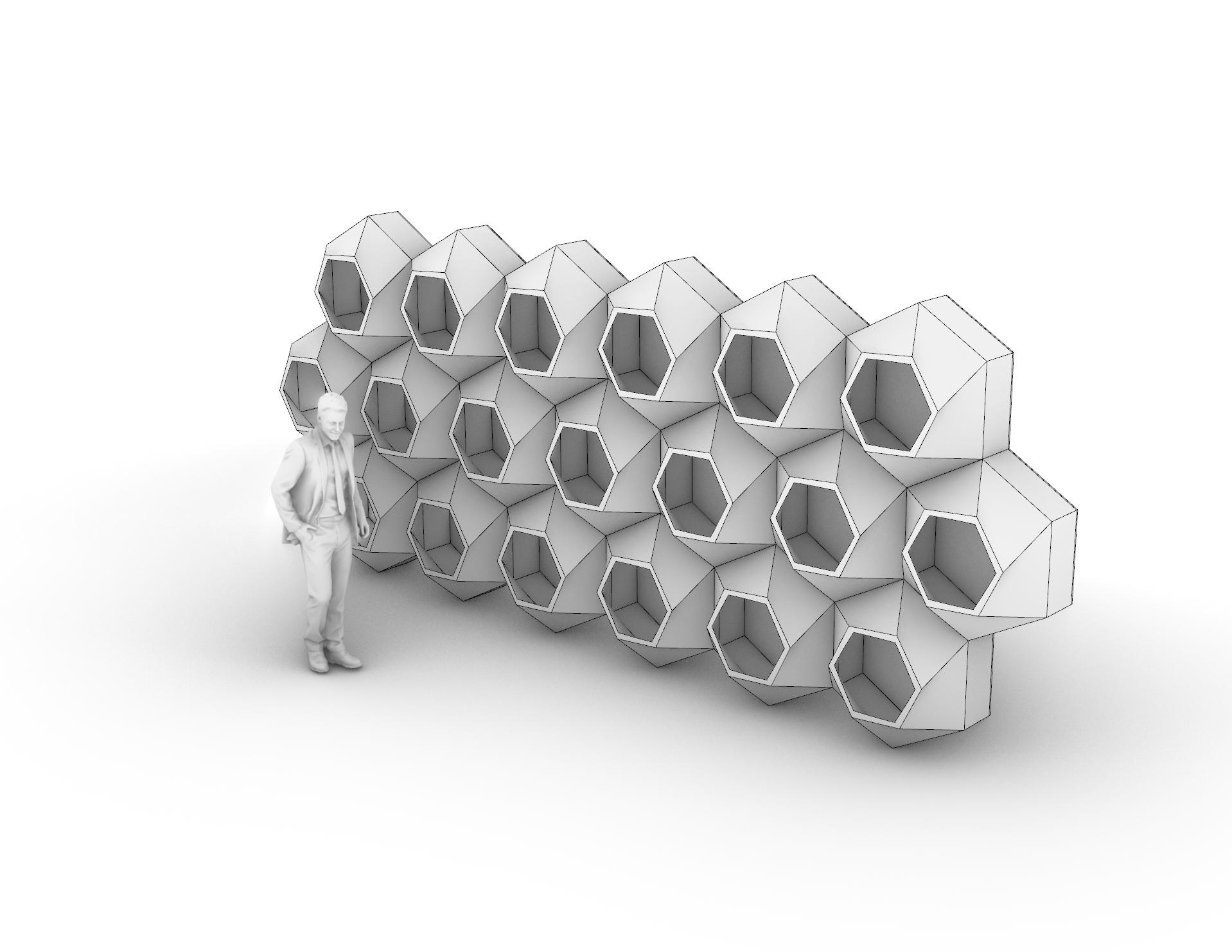
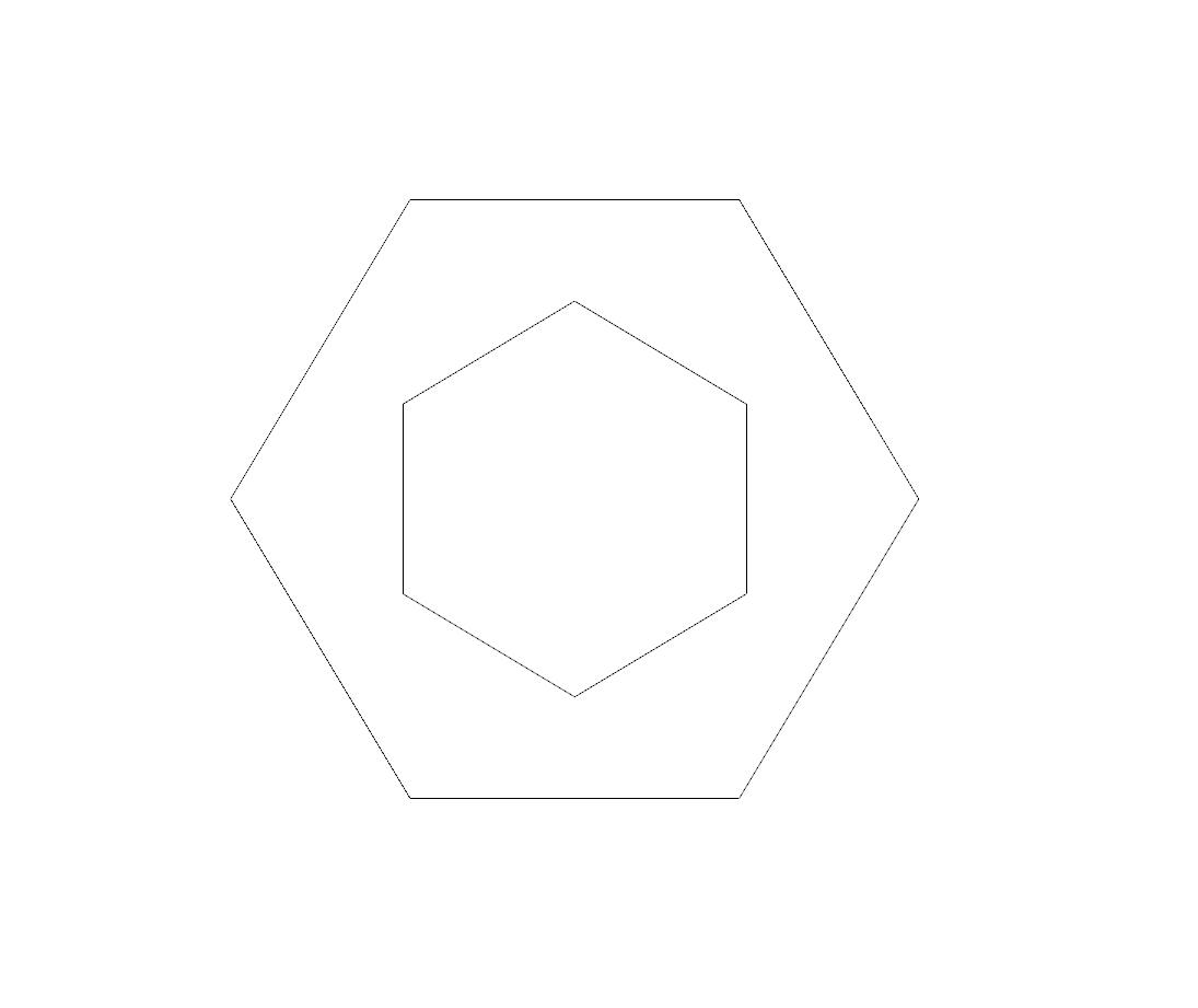
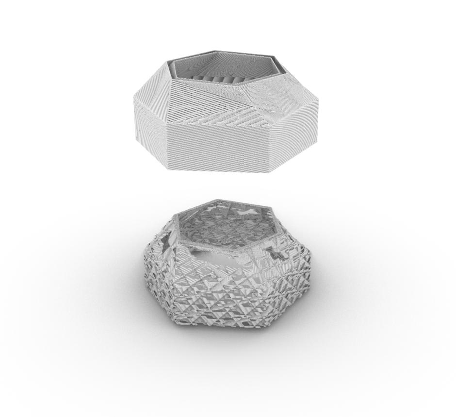
Trying to imporve upon my last design I moved away from the pentagon and chose to use a hexagon instead. This shape lends it self to be aggregated much cleaner. There are no gaps and the symmetrical design means there orientation is not as important as in my previous iteration. Along with this I improved the desing by making the front face more intresting

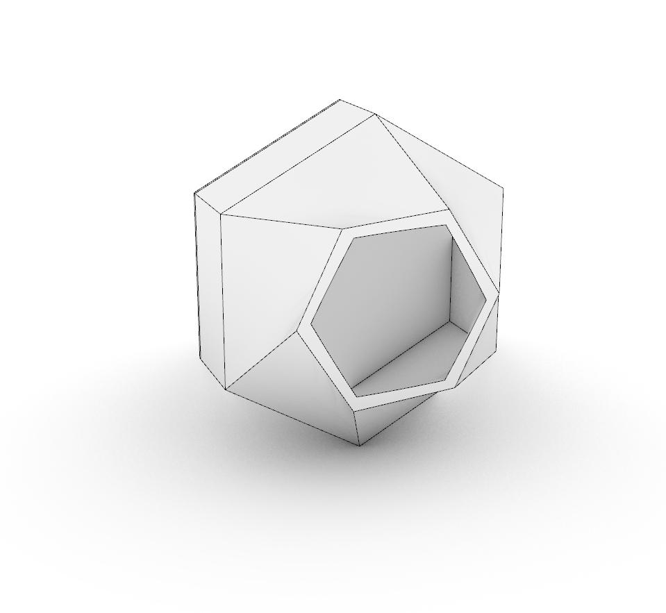
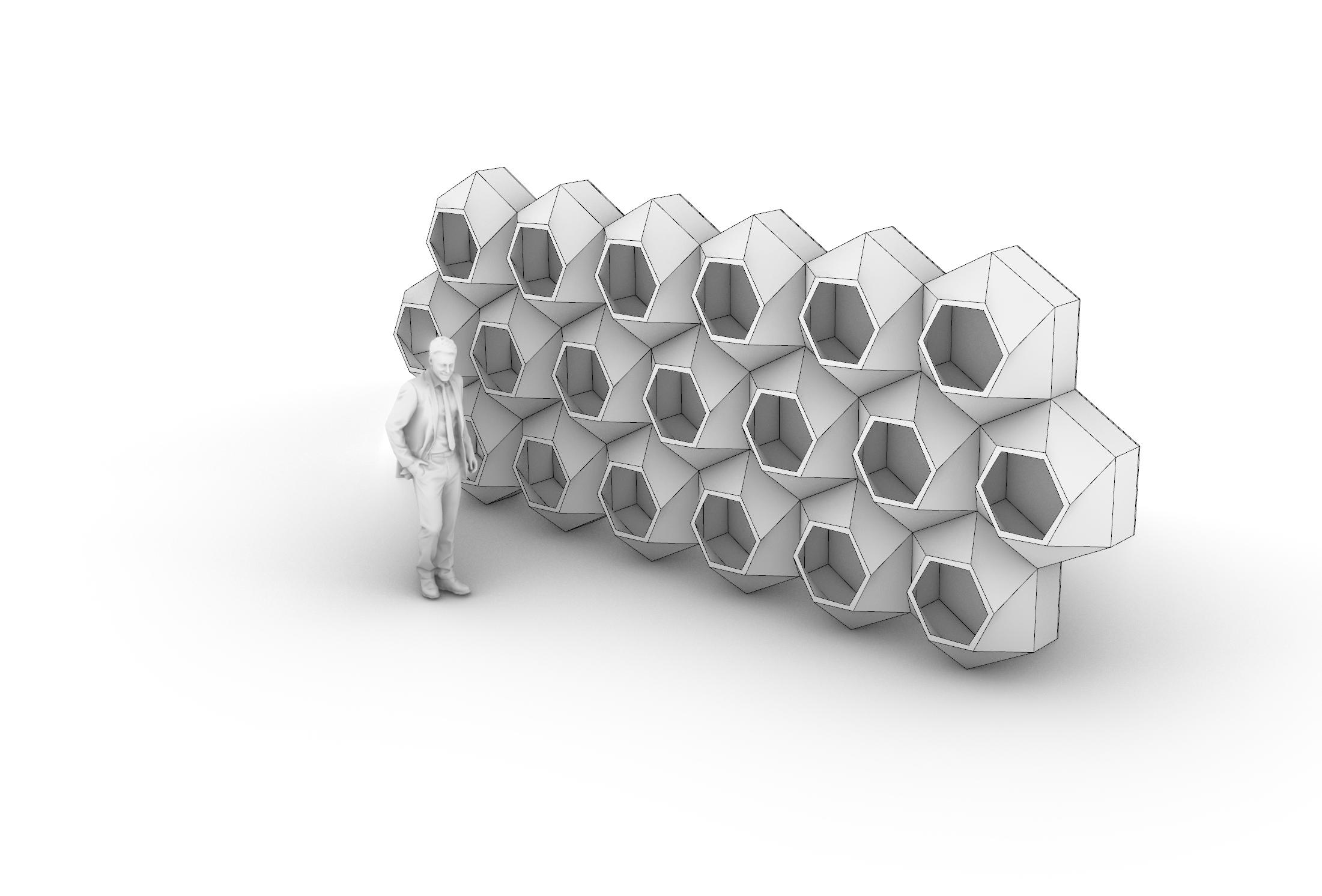
with a sprial design that also serves as storage. The shape also allows the unit to be rotated 180 degrees that way it can be access from both sides if needed. I imagined the scale of this module to be roughly 3’ tall making it large enough to have ample storage within the unit.
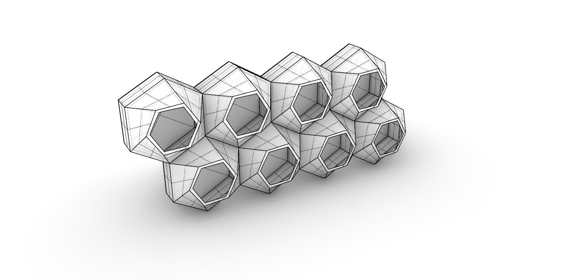
1_ Module 2 unit diagram
2_ Module 2 unit diagram
3_ Rhino module aggregation
4_ prusa obj exported into Rhino
5_ Single unit in Rhino
6_ Unit aggregation with scale figure

DESCRIPTION
Tolerance and Joints
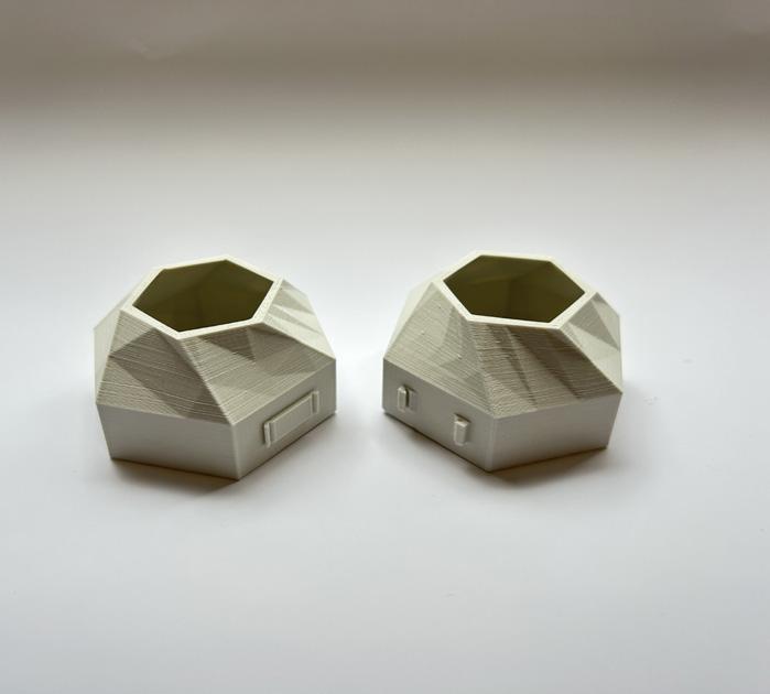
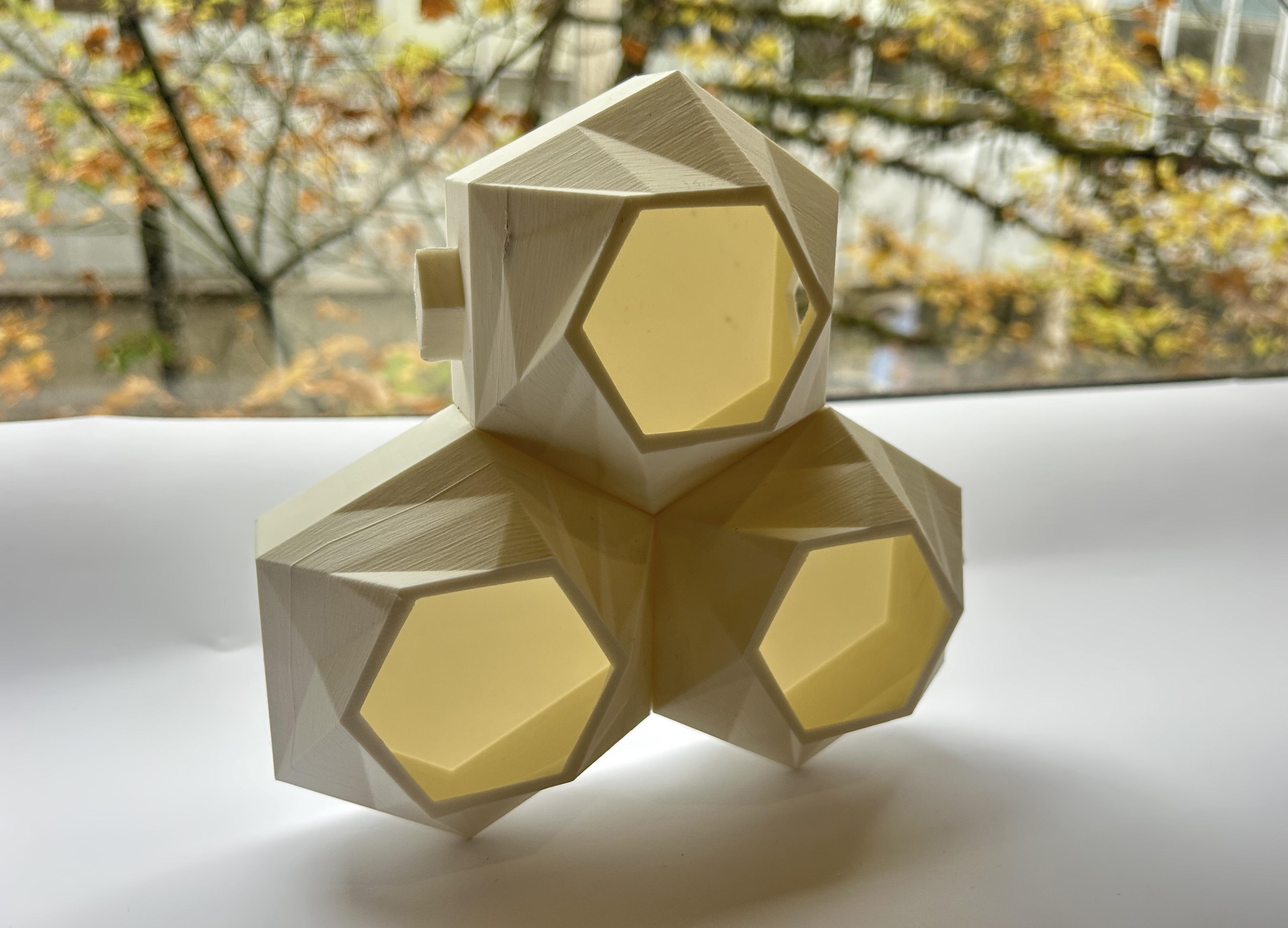
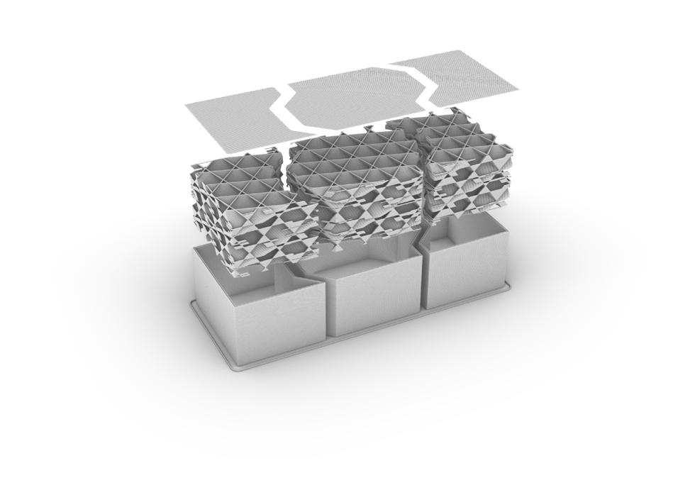
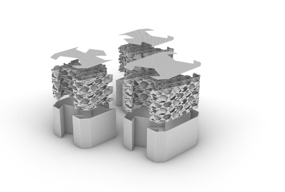
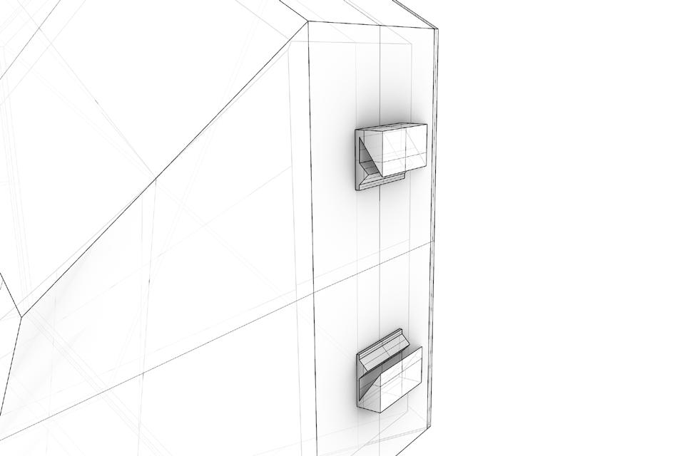
Once I landed on a final shape I began exploring the joinary between units. I started looking at a lock and key connection as seen in figure 1 and 2. This male and female connetion would allow for an easy assmbly, however, in practice these connections where prone to breaking and did not allow for a flush connect. For these reasons I switched to a mortise and tenon
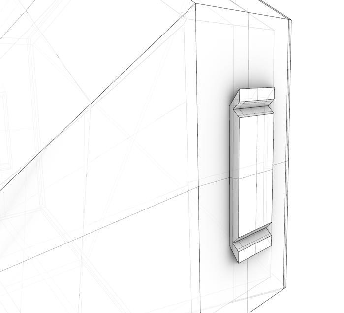
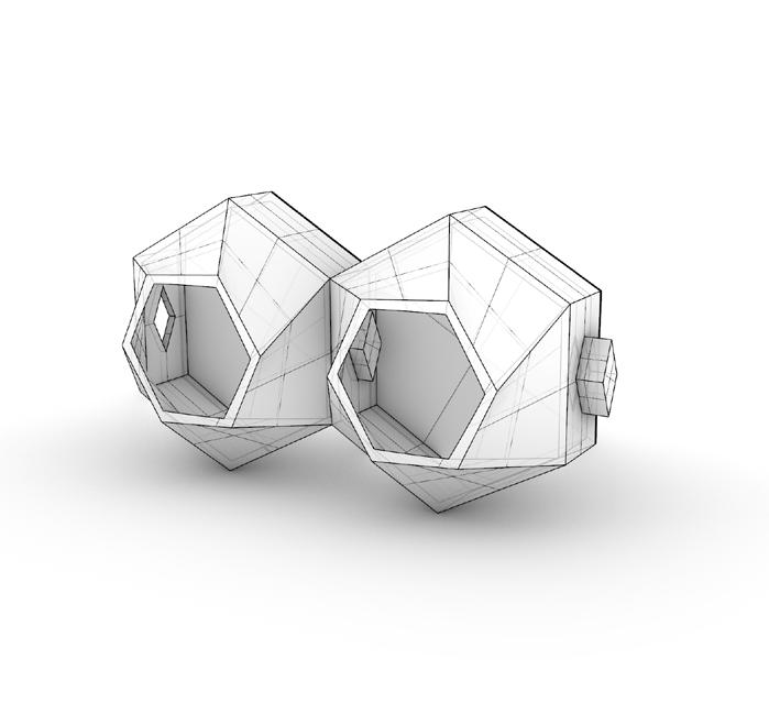
system. Although more symplistic this connection allows for a seamless joint with minimal gaps and resists from both lateral and vertical loads. The system as a whole printed very well without supports but I do think adding supports would have been beneficial.
