
International Research Journal of Engineering and Technology (IRJET) e-ISSN: 2395-0056
Volume: 12 Issue: 07 | Jul 2025 www.irjet.net p-ISSN: 2395-0072
International Research Journal of Engineering and Technology (IRJET) e-ISSN: 2395-0056
Volume: 12 Issue: 07 | Jul 2025 www.irjet.net p-ISSN: 2395-0072
Syed Saheeq Ahamed1, Bhaskar G2, Dr. C S Ravindra Sagar3
12ResearchScholars, Department of Mechanical Engineering, SSIT, Tumakuru, Karnataka, India
2Assistent Professor, Department of Mechanical Engineering, SSIT, Tumakuru, Karnataka, India
3Professor, Department of Mechanical Engineering, SSIT, Tumakuru, Karnataka, India
Abstract - In the present investigation a new Aluminium alloy LM26 is selected as a matrix and reinforced with Silicon Carbide (SiC) particle from 0% to 10% at a regular interval of 2% is tested for dry sand abrasive wear to study the wear behavior under various conditions.Thetestisconductedunder different loads 10N, 20N and 30N and different time frame of 15min, 30 min and 45 min. In this experiment the speed of rubber drum is kept constant at 200RPM, grain size of dry silica sand at 312 micron and sand flow rate at 200grams/min. The specimen and test were conducted as per ASTM G 65-81 standards. Thespecimeninitialweightandfinal weights were recorded at regular intervals. The data were collected, tabulated and graphs were plotted to understand the behavior of materials.
The automobile body parts are designedwithanobjectivethat whenever a collision occurs, it should absorb the impact energy and not to transmit the crack to next. Hence whenever a body parts are designed, the material selected which has a property of absorbing the impact strength and crack or break itself and not to damage the next parts so as to minimize the damage. Hence assessment of impact strength of novel materials is a must. In the present investigation LM26 Aluminium alloy reinforced with SiC particle at different percentage and tested for Izod and Charpy impact strength The specimens were prepared as per ASTM D256 for Izod and ASTM E23 for Charpy standards. The tests are conducted on NABL accredited and calibrated labs. The obtainedresultsare tabulated and graphs are plotted to observe the behavior.
Further the SEM images of the fractured surfaces are also conducted at 500X to study the micro structure characterization to assess particle distribution, micro cracks and phase of solidification.
Key Words: Drysandabrasivetest,LM26,SiC,ASTMG6581, Impact Strength, ASTM D256 for Izod, ASTM E23 for Charpy,SEM500X,Microstructurecharacterization.
Materialwearisacommoninautomobileandconstruction partsasthecomeacrossasituationofbeingincontactwith soil sliding. Hence designing a parts for these application, onehastoconsiderwearresistantpropertiesofamaterials.
Aluminiumanditsalloysarethenextpromisingmaterials forautomobileandalliedindustriesaftersteel.Thisisbased on their properties like high strength to weight ratio, corrosion resistant, Easy to cast and many more. By reinforcing a suitable ceramic particles its overall performancecanbeimprovedandgetsclosertothatofsteel.
Metal MatrixComposites(MMCs)reinforcedwithceramic particles significantly enhance the mechanical and wear properties of materials, effectively limiting deformation under mechanical rubbing or sliding conditions [1,2,3,6]. Theseimprovementsareparticularlybeneficial fordesign engineersintheautomotiveandaerospaceindustries,where components are subjected to demanding operational stresses[4].
LM26 Aluminium alloy reinforced with Silicon Carbide particles (SiC) has shown great improvement in Tensile strength,Ultimateyieldstrength,compressivestrengthand hardness[1] TheMMC’shaveshowngoodimprovementin Dry sliding Pin Disc experiment also. Hence the MMC is testedforthreebodydrysandabrasivetestandimpacttest, bothIzodandCharpytesttoassessthematerialbehavior. Thecompositesarefabricatedusingaliquidmetallurgical routecombinedwiththestirringmethodtoensureuniform distributionofthereinforcementwithinthematrix[1].After casting,thecompositesaremachinedtoproducestandard testspecimensinaccordancewithASTMspecifications,with varying percentages of SiC reinforcement introduced to studytheireffect[13,14].
LM26AluminiumalloyisadesignatedgradeofAluminium alloy primarily used in casting applications, where "LM" refers to Linear Monolithic [3]. It belongs to the Al-Si (Aluminium-Silicon) family of alloys, renowned for their excellent castability, low shrinkage, and superior wear resistance[1]. LM26 is widely utilized in applications that demand moderate to high stress endurance, particularly whereahighstrength-to-weightratio,goodwearresistance, and corrosion resistance are critical factors [3,4,5,6,10,12].ASM standard composition for LM26 Aluminiumalloy;[1]
Volume: 12 Issue: 07 | Jul 2025 www.irjet.net
1.1
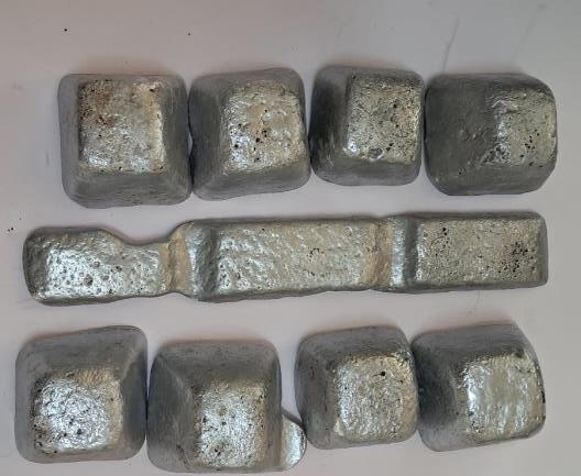
Silicon carbide (SiC), also known as carborundum, is a materialrenownedforitsexceptionalthermal,mechanical, and electrical properties [1,3,4]. These unique characteristicsmakeSiChighlyvaluableacrossawiderange of applications, including power electronics, abrasive materials,heatexchangers,andwear-resistantcomponents. SiCisrecognizedasthethirdhardestmaterialafterdiamond andboroncarbide[4].Itsremarkablehardnessarisesfrom its distinctive crystal structure, where silicon and carbon atomsaretightlybondedinatetrahedralconfiguration.This strong covalent bonding provides SiC with outstanding strength, hardness, and high resistance to wear and abrasion.
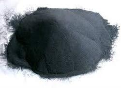
Metal Matrix Composites (MMCs) can be fabricated using various methods, including liquid infiltration, powder metallurgy,diffusionbonding,andothers.Amongthese,the liquid metallurgical process, also known as the casting process,iswidelypreferredduetoitssimplicity,economical, suitabilityformassproduction,lessmaterialwastage,andthe factthatitdoesnotrequirehighlyskilledtechnicians.
However,anotabledrawbackofthismethodisthetendency ofheavyalloyingelementsandreinforcingparticles,suchas silicon carbide (SiC), to settle at the bottom of the molten Aluminiumalloyduringmelting
Toovercometheselimitations,anovelstircastingmethodis employed.Thistechniqueinvolvesmechanicalstirringofthe moltenalloy-reinforcementmixtureatacontrolledspeedfor aspecificdurationbeforepouringitintomoulds.Intheliquid stircastingprocess,thebaseAluminiumalloyisfirstmelted between650to700oC,andSiCparticlesarepreheattreated toeliminatemoistureandreduceagglomeration,areaddedin therequiredquantity.
The mixture is stirred at approximately 200 RPM for 10 minutes to ensure homogeneous dispersion of the reinforcementparticles.Subsequently,themoltencomposite ispouredintosteeldiestoformplatesofthickness10mm The mouldsare allowed to cool andsolidify over 45 to 60 minutes,afterwhichthesolidifiedpartsareejected,marked according to their reinforcement percentage. Finally, the casted components are machined according to ASTM standardspecificationstoproducetestspecimenssuitablefor mechanicalandweartestingandImpacttesting
International Research Journal of Engineering and Technology (IRJET) e-ISSN: 2395-0056
Volume: 12 Issue: 07 | Jul 2025 www.irjet.net p-ISSN: 2395-0072
The Sand Abrasive Wear Test is a widely used method to evaluate the abrasion resistance of materials, particularly metals, composites, andcoatings, under the action of hard particleslikesand especiallythose exposed to erosiveand abrasive environments. It simulates real-life conditions where components are exposed to abrasive environments like mining, agriculture, construction machineries, automobile industries, etc. The test simulates real-world conditions where materials are subjected to friction and impactfromhardparticlessuchassand,dust,orgrit.
The main objective of the sand abrasive wear test is to measurethematerial'sresistancetoabrasivewearcausedby loose abrasive particles under controlled conditions. This helps in selecting materials for particular applications in designingmachineelement.
Thetestinvolvesrubbingorimpactingasamplewitha known quantity of abrasive material (usually silica sand) under specific loads, speeds, and durations. The abrasive particlesremovematerialfromthesurfacebymicro-cutting, plowing, or fragmentation mechanisms. The amount of materiallost(usuallymeasuredbyweightloss)indicatesthe wearresistanceofthetestedspecimen.Themorematerial removedindicateslessresistanceandviceversa.
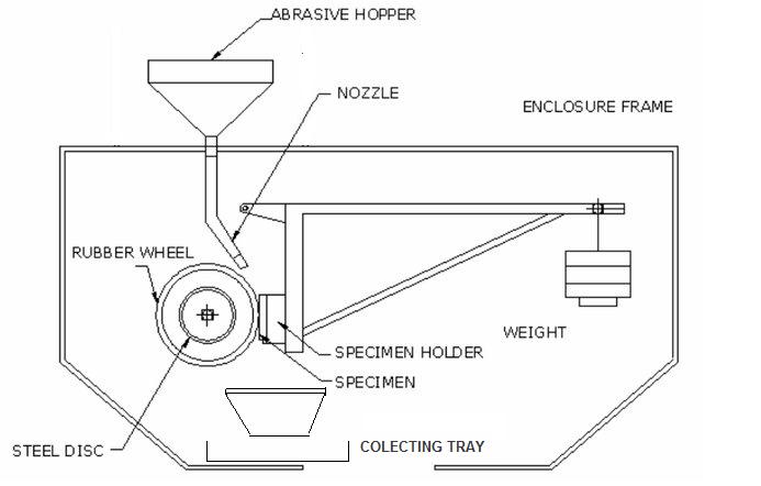
Threebodydrysandrubberwheeltestsetuphavearotating rubberwheelorsteelpressesagainstthetestspecimenand dry sand poured in between them at a constant flow rate. This makes the test specimen to wear in the form of fine particle.Afteratimeinterval,theweightdeferenceisnoted downandtabulated.
ThetestspecimenwerepreparedasperASTMG65,10X25 x75mmwhichwillexactlyfitinthespecimenslot.
International Research Journal of Engineering and Technology (IRJET) e-ISSN: 2395-0056
Volume: 12 Issue: 07 | Jul 2025 www.irjet.net p-ISSN: 2395-0072
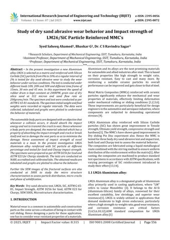
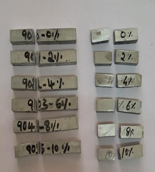
Machined standard test specimens
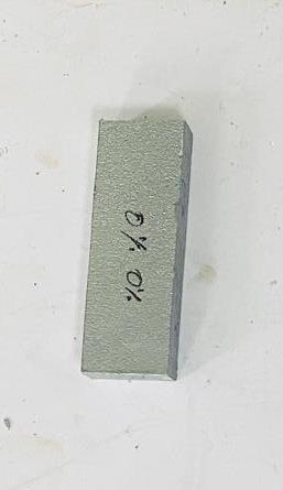
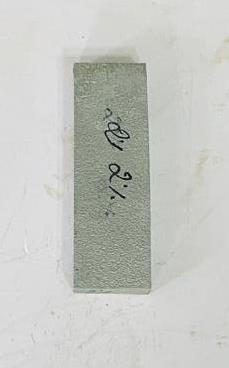
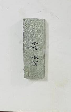
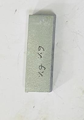
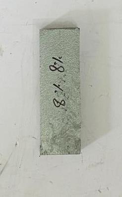
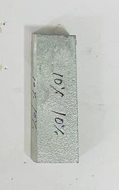
Fig 3.4 Machined Sand abrasive specimens before testing
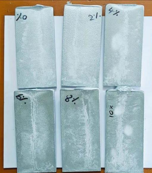
Specimens after the test, after 30N
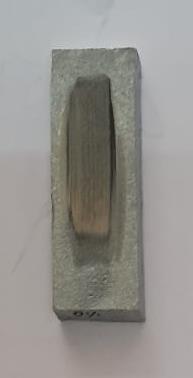
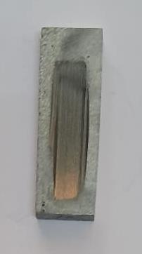
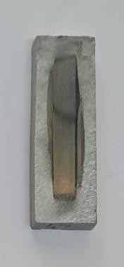
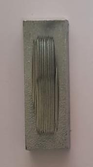
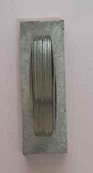
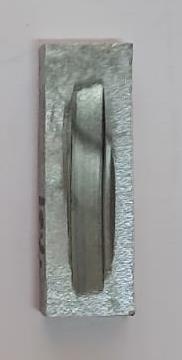
Fig 3.5 sand abrasive test Specimens after testing
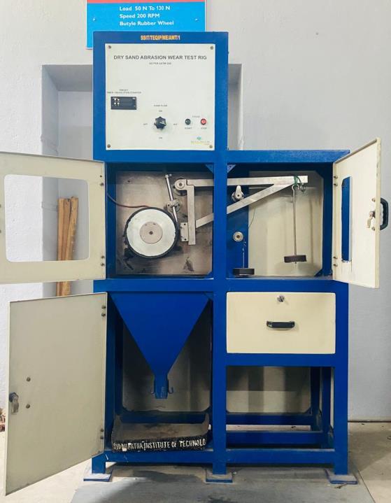
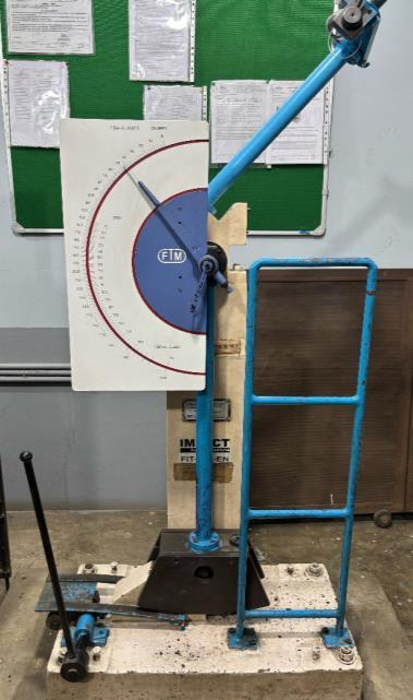
Experimental setup
The dry sand abrasive test was conducted by keeping followingparameters;
SpeedofRubberdisc =200rpm
Sandflowrate =200Grams/Min
Sandparticlesize =312micronor45to50Gritsize
Timeintervals =15min,30min,45min
Loads =10N,20N,30N
ResultsTable
Speed =200rpm,Load=10N
Table No: 4.1 Weight loss in grams for Different SiC% for different time frame
Similardatachartsweremadefor20Nand30Nloads.
An impact test is a mechanical test used to determine the toughnessofamaterial,specifically,howmuchenergyitcan absorbduringfracture.Thisiscrucialforunderstandinghow materialsbehaveundersuddenorshockloading.
Purposeofimpacttestistoevaluateamaterial'sabilityto resistsuddenshocksorloadsalsotodetectbrittlevs.ductile behavior.
PrimarilytherearetwotypesofImpactTests
CharpyImpactTest(mostwidelyused)andIzodImpactTest
Charpy Impact Test
Specimenissupportedhorizontallyandstruckinthemiddle, notchedspecimenandmeasuresenergyabsorbedtofracture thesample.
Izod Impact Test
Specimenisheldvertically,Struckatthetopabovethenotch andthisalsousesanotchedspecimen.
Notch Type: V-notch,U-notch(concentratesstress).
ImpactEnergy:Measuredinjoules(J).
FractureAppearance:Indicatesductileorbrittlefailure.
StandardSpecimenDimensions
ForCharpytestthespecimenisasperASTME23
Size:10mm×10mm×55mm,and2mmdeepV-notch,45° angle.
International Research Journal of Engineering and Technology (IRJET) e-ISSN: 2395-0056
Volume: 12 Issue: 07 | Jul 2025 www.irjet.net p-ISSN: 2395-0072
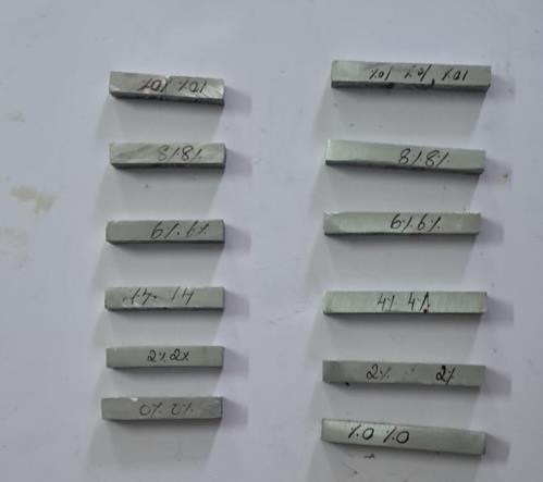
Fig 4.1 Standard test Specimen Charpy
ForIzodtestthespecimenisasperASTMD256 Size:10mm×10mm×75mm,and2mmdeepV-notch, 45°angle.
2025, IRJET | Impact Factor value: 8.315 |
Izod Impact test results Crosssectionalareaunderthecurve=8x10mm2
Table No 4.1 Izod Impact Test Results
Volume: 12 Issue: 07 | Jul 2025 www.irjet.net
Charpy Impact test results
Cross
Sl
Table No 4.2 Charpy Impact Test Results
Microstructure characterization plays a vital role in understanding and improving the performance of metal matrixcomposites(MMC’s).Itrevealsmaterialcomposition and distribution, evaluates interface quality or bonding of matrix and reinforcement, correlates with mechanical properties, helps detect defects, assists in process optimizationandmanymore.
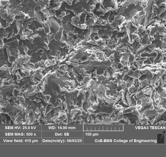
In the present investigation the fractured surface of Izod impacttestspecimensaretakenforanalysis.Thespecimens arecutforathicknessof8to10mmandSEMimagesat500X aretakenfordiscussion.
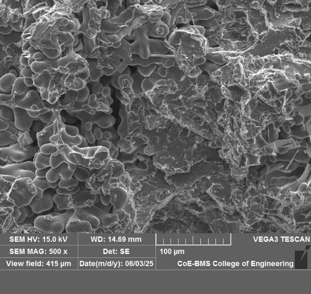
Thefigure5.1shows500XSEMimageof2%SiCreinforced MMC, from images we can see rough and fractured morphologyindicatingbrittlefracture.PresenceofDendritic structureandsemidendriticstructureindicatesAl-Sialloy, inLM26AluminiumalloySiliconisoneofthemajoralloying elementandSEMimagesconfirmit.
The figure 5.2 shows 2% SiC reinforced SEM images, indicatesclusteredSiCparticleswithcylindricalorrodlike structures.Thereinforcementarerareandoddlydistributed as2%SiCissmallweightpercentage.
International Research Journal of Engineering and Technology (IRJET) e-ISSN: 2395-0056
Volume: 12 Issue: 07 | Jul 2025 www.irjet.net p-ISSN: 2395-0072
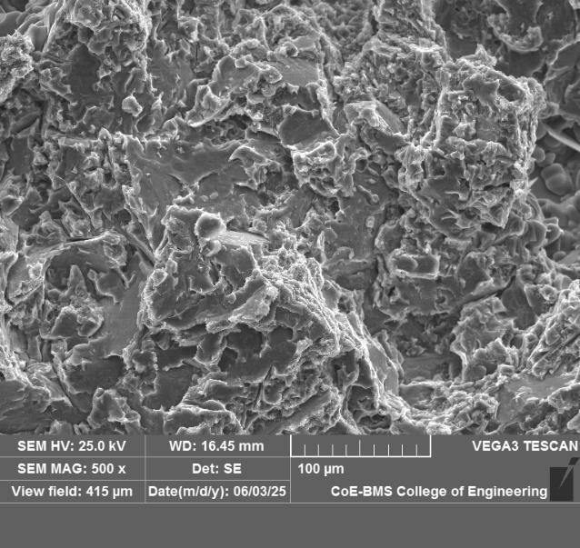
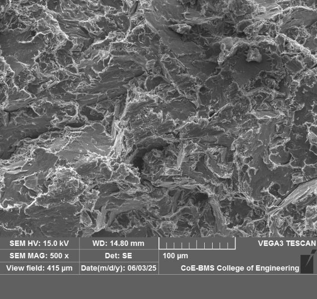
The figure 5.3 shows 500X SEM images of 8% SiC reinforcement LM26 Al MMC’s. In the image it can clearly observedthatuniformlydistributedSiCparticleandreduced Dendritic structure indicate enhanced mechanical properties.500XimagealsoshowsSiCparticlesurrounded bymatrixmaterials.
The figure 5.4 10%SiC reinforcedLM26Al alloy,theSEM images shows high distribution of SiC particles, increased reinforced particles enhanced the brittleness in material. Also reinforcement and matrix bonding reduced due to reduced wetting of reinforcement as matrix become inadequatetocompletelywettheparticles.Hencethereis been an overall down trend in mechanical properties but wereintribologicalpropertiesshowscontinuedtrends.
6. Results and Discussions
For Dry Sand abrasive test, the data was collected and tabulatedasshowninTableNo4.1,thevariousgraphsare plotted and different plots indicates the material as discussedasfollows.
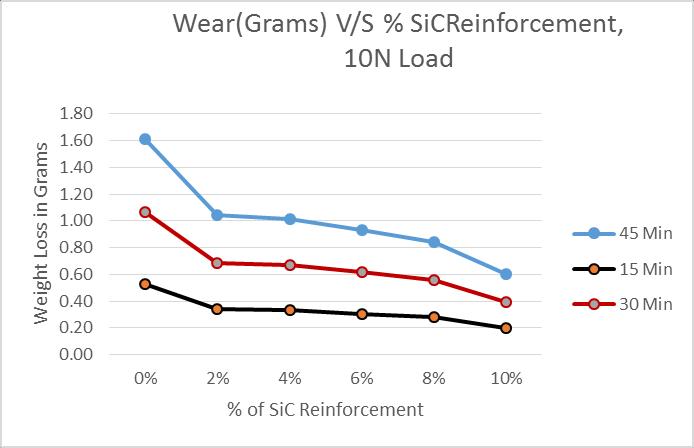
Thefigure6.1showstheplotsbetweenWearingramsV/S %SiC reinforcement for 15 min, 30 min and 45 min is as shown in diagram, the plot indicates as percentage of SiC increases, the wear decreases. This is due to increase in percentage of SiC induces the brittleness and reduces the wearofmaterials. Also15minlineisatthebottomand45 minlineattopindicateswearincreasesastimeincreases. TheGraphsfor20Nand30Nloadshowssimilartrends.
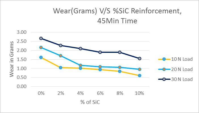
The figure 6.2 shows the graphs having the relationship betweenwear(ingrams)andthepercentageofSiC(Silicon Carbide) reinforcement in a MMC tested for 45 minutes under three different loads: 10 N, 20 N, and 30 N. For all threeloadconditions,weardecreasesasthepercentageof SiCreinforcementincreases.ThisindicatesthataddingSiC particles improves wear resistance of the material. The highest wear is observed across all loads, with maximum wearunder30Nload.Wearislowestunderthe10Nload. However,evenathigherloads,thepresenceofSiChelpsin reducingwearcomparedtotheunreinforcedmaterial.
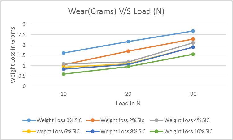
Thefigure6.3showstherelationshipbetweenWeightLoss (grams)andAppliedLoad(N)fordifferentpercentagesof SiC reinforcement in a material. For all SiC percentages, weightlossincreaseswithincreasingload(from10Nto30 N).Atallloadlevels,materialswithhigherSiCcontentshow
International Research Journal of Engineering and Technology (IRJET) e-ISSN: 2395-0056
Volume: 12 Issue: 07 | Jul 2025 www.irjet.net p-ISSN: 2395-0072
lower weight loss. The sample with 0% SiC consistently exhibits the highest weight loss. The 10% SiC reinforced materialshowstheleastweightlossacrossallloads.Higher loadsresultingreaterwearormaterialloss.
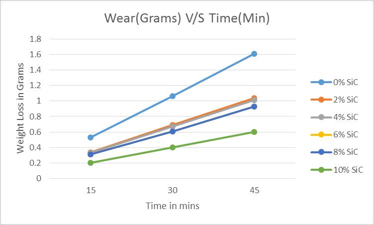
Thefigure6.4depictstherelationshipbetweenWeightLoss (ingrams)andTime(inminutes)formaterialsreinforced withvaryingpercentagesofSiC(SiliconCarbide).ForallSiC reinforcementlevels,weightlossincreaseswithtime(from 15 to 45 minutes). Longer test durations result in higher cumulativewear.0%SiC(unreinforced)showsthehighest weight loss at every time interval. 10% SiC consistently shows the least weight loss across time intervals. Wear (weightloss)isdirectlyproportionaltotimeofexposureto wearconditions.
HigherSiCreinforcementsignificantlyreduceswear, even overextendeddurations.Thishighlightstheeffectivenessof SiCinenhancingthedurabilityandwearresistanceofthe material.
Test:
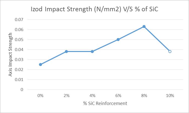
Thefigure6.5 showstheIzodImpactStrength(N/mm²)ofa materialasafunctionofSiC(SiliconCarbide)reinforcement
percentage. From 0% to 8% SiC, there is a noticeable increase in impact strength, the impact strength steadily increases and peaks at 8% SiC. This suggests that SiC reinforcementup to8% enhancesthe material'sabilityto absorbimpactenergy.At10%SiC,theimpactstrengthdrops sharply,thisreductioncouldbeduetobrittlenessinducedby excessive SiC content, leading to a decline in toughness. OptimalSiCreinforcementforimpactstrengthisaround8%, wherethematerialachievesitshighesttoughness.Beyond 8%, further reinforcement reduces impact strength, likely duetoincreasedbrittleness.TherelationshipbetweenSiC% andimpactstrengthisalmostlinear,withanoptimumpoint at8% followedbyadecline.
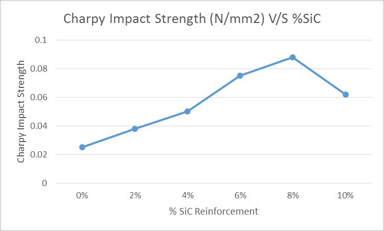
Thefigure6.6representstherelationshipbetweenCharpy Impact Strength (N/mm²) and percentage of SiC (Silicon Carbide)reinforcementinacompositematerial.From0%to 8% SiC, Charpy impact strength steadily increases. This suggests that SiC reinforcement up to 8% improves the material’s ability to absorb impact energy. At 8% SiC, the Charpyimpactstrengthreachesitsmaximum.At10%SiC, impactstrengthdrops,indicatingareductionintoughness. This is likely due to increased brittleness at higher SiC content, similar to trends seen in the Izod impact test. Optimal SiC reinforcement for maximum Charpy impact strengthisaround8%.Beyondthis,thecompositebecomes morebrittle,leadingtoadecreaseinimpactstrength.The trend mirrors the behaviour of many composites: reinforcementimprovesmechanicalpropertiesuptoapoint, afterwhichitcompromisesductilityandtoughness.
In the present work, LM26 Al alloy reinforced with SiC particle (325 Grit size) was successfully done to produce MMC’s. For casting a specimen, a stir casted machine was used which stir the molten composition at 200rpm for 10 minbeforepouringitintosteelmold.TheSandAbrasiveand ImpactstrengthbothIzodandCharpytestspecimenswere machined as per ASTM standard and was tested in a respectivemachine.Alsotounderstandthemicrostructure
International Research Journal of Engineering and Technology (IRJET) e-ISSN: 2395-0056
Volume: 12 Issue: 07 | Jul 2025 www.irjet.net p-ISSN: 2395-0072
thespecimenswerestudiedunderSEMfor500X.Theresults were obtainedandtabulated. The graphsare plottedand discussed in previous section. The following conclusion weredrawnafterthesuccessfulcompletionofproject.
1. In sand abrasive test, the results depicts that, for all threeloadconditions,weardecreasesasthepercentage of SiC reinforcement increases. This indicates that adding SiC particles improves wear resistance of the material.Thehighestwearisobservedacrossallloads, with maximum wearunder 30N load. Wear islowest underthe10Nload.However,evenathigherloads,the presenceofSiChelpsinreducingwearcomparedtothe unreinforcedspecimen.
2. ThesandabrasivetestresultsalsoindicatesWeightLoss and Time for materials reinforced with varying percentages of SiC. For all SiC reinforcement levels, weightlossincreaseswithtime(from15to45minutes). Longertestdurationsresultinhighercumulativewear. 0%SiC(unreinforced)showsthehighestweightlossat every time interval. 10% SiC consistently shows the leastweightlossacrosstimeintervals.Wearisdirectly proportional to time of exposure to wear conditions. Higher SiC reinforcement significantly reduces wear, even over extended durations. This highlights the effectivenessofSiCinenhancingthedurabilityandwear resistanceofthematerial.
3. The impact test results shows the Izod and charppy Impact Strength of a material as a function of SiC reinforcementpercentage.From0%to8%SiC,thereisa noticeable increase in impact strength and peaking at 8%SiC.ThissuggeststhatSiCreinforcementupto8% enhancesthematerial'sabilitytoabsorbimpactenergy. At 10% SiC, the impact strength drops sharply, this reduction could be due to brittleness introduced by excessiveSiCcontent,leadingtoadeclineintoughness.
[1] Bhaskar G, Dr. C S Ravindra Sagar, Sudarshan B B, DEVELOPMENT OF LM26 AL ALLOY REIN-FORCED WITH SIC PARTICLE FOR ASSESSING TENSILE, COMPRESSION AND HARD-NESS PROPERTIES, International Research JournalofEngineeringandTechnology(IRJET)Volume: 12 Issue:06|Jun2025,Page945-953
[2]K.V.SreenivasRao,SanmanS,SanjeevamurthyandT.P. Bharathesh,(2016)DRYSANDABRASIVEWEARBEHAVIOR OFCHILLCASTALUMINUMBORONCARBIDECOMPOSITES, ARPNJournalofEngineeringandAppliedSciences,VOL.11, NO.1,JANUARY2016ISSN1819-6608
[3] BhaskarG,SyedSaheeqAhamed,Dr.CSRavindraSaga, "EvaluationofWearBehaviorofLM26/SiCMMC’susingPin
on Disc Experiment", 2025, International Journal For MultidisciplinaryResearch,volume=7,Issue=4,ISSN:25822160,SkyResearchPublicationandJournals
[4] T. Satish Kumar, R. Raghu, Titus Thankachan, Robert Čep,KanakKalita,(2024),Mechanicalpropertyanalysisand drysandthree bodyabrasivewearbehaviourofAZ31/ZrO2 composites produced by stir casting, Scientific Reports | (2024) 14:1543 | https://doi.org/10.1038/s41598-02452100-9
[5] Zhongxin Wang, Long Sun, Dong Wang, (2023) AbrasiveWear Properties ofWear-Resistant Coating on Bucket Teeth Assessed Using a Dry Sand Rubber Wheel Tester, Materials 2024, 17, 1495. https://doi.org/10.3390/ma17071495
[6]K.Ligiera,J.Napiórkowskia,M.Lemechaa(2020),Effect ofAbrasiveSoilMassGrainSizeontheSteelWearProcess,K. Ligieretal.,TribologyinIndustryVol.42,No.2(2020)165176
[7] T. Satish Kumar 1, R. Raghu 2, Titus Thankachan 3, Robert Čep 4 & Kanak Kalita 5,6* (2024), Mechanical propertyanalysisanddrysandthree bodyabrasive wear behaviour of AZ31/ZrO2 composites produced by stir casting. Scientific Reports | (2024) 14:1543 | https://doi.org/10.1038/s41598-024-52100-9
[8]ZhongxinWang1,2,LongSun2,*,DongWang1,BoSong 2,ChangLiu2,ZhenningSu2,ChaobinMa3andXiaoyong Ren3,*(2024)AbrasiveWearPropertiesofWear-Resistant CoatingonBucketTeethAssessedUsingaDrySandRubber Wheel Tester, Materials 2024, 17, 1495. https://doi.org/10.3390/ma17071495
[9] Priyaranjan Samal*, Pandu R. Vundavilli, (2019), Investigation of impact performance of aluminum metal matrixcompositesbystircasting,IOPConf.Series:Materials ScienceandEngineering653(2019)012047,IOPPublishing, doi:10.1088/1757-899X/653/1/012047
[10]C.Parswajinan1,a*,B.VijayaRamnath2,b,S.Abishek3, c, B. Niharishsagar4, d, G.Sridhar5,e (2018) Hardness and impactbehaviourofaluminiummetalmatrixcomposite,IOP Conf.Series:MaterialsScienceandEngineering390(2018) 012075doi:10.1088/1757-899X/390/1/012075
[11]SadashivaM1,ShivanandHK2,(2018),Characteristic InvestigationonImpactStrengthofAluminiumBasedHybrid Composite Plates Weld by FSW, International Journal of Engineering&Technology,7(3.12)(2018)120-127
[12] Arpita Chatterjee 1,2, Soumyadeep Sen 3, Subhodeep Paul1,PallabRoy4,"FabricationandCharacterizationofSiCreinforced Aluminium Matrix Composite for Brake Pad
International Research Journal of Engineering and Technology (IRJET) e-ISSN: 2395-0056
Volume: 12 Issue: 07 | Jul 2025 www.irjet.net p-ISSN: 2395-0072
Applications", 2023, Metals 2023, 13, 584. https://doi.org/10.3390/met13030584 https://www.mdpi.com/journal/metals
[13] J. Jeykrishnan1*, B. Vijaya Ramnath1, X. Hervin Savariraj2,"InvestigationonTensileandImpactBehaviorof AluminumBaseSiliconCarbideMetalMatrixComposites", Indian Journal of Science and Technology, Vol 9(37), DOI: 10.17485/ijst/2016/v9i37/101979,October2016
[14]S.N.Vijayan,SamsonJSChelladurai,“NumaricalAnalysis ofimpactBehaviourofLM26/ZrB2 CompositeusingFinite Element Method”, International conference on AdvancementsinMaterialsandManufacturingEngineering–ICAMME2021,AIPConf. Proc.2527,020007-1-010007-6, PublishedbyAIPPublishing.
9. BIOGRAPHIES


SyedSaheeqAhamed syedsaheeq123@gmail.com
Mr.BhaskarG bhaskarg@ssit.edu.in
Dr CSRavindraSagar ravindrasagarcs@ssit.edu.in
© 2025, IRJET | Impact Factor value: 8.315 | ISO 9001:2008
| Page