
International Research Journal of Engineering and Technology (IRJET) e-ISSN:2395-0056

Volume: 09 Issue: 08 | Aug 2022 www.irjet.net p-ISSN:2395-0072
A review on fast wireless charging methods for Electric Vehicles.
Yogesh A.M1, Dr.Radhakrishna K.R.2
1Selection Grade lecturer, Dept. of EEE, Govt. polytechnic, Mosalehosalli, Hassan
2Professor and Head, Department of Electrical and Electronics Engineering, R.I.T, Hassan ***
Abstract In this fast-evolving electrification process, Electric vehicle (EVs), are expected to replace Conventional Vehicles at a desirable rate as Electrified transportation will help to reduce green-house gas emissions and increasing petrolprices.However,todateEVs are not highlyattractive to consumersindensecountrieslikeIndia,dueto their unsatisfactorybattery charging characteristics and high cost. The currently practiced conductive charging method makes the usage of EVs inconvenience due to poor charging infrastructures, accidental electric hazards and poor battery capacities. The adoption of wireless power transfer (WPT) system caneliminate all of the charging troubles of EVs. However, theWPT systems in existing EVs have large air gaps between the transmitter coil and the receiver coil, posing a hurdle that prevents success. The large air gap cause issues such as a loose coupling, low efficiency, and troublesome electromagnetic compatibility (EMC). An in-wheel WPT systemcanserveasasolutiontoaddresstheissuesarisingdue tothelargeairgap.Inthispaper, weproposetwomethodsto enhance the charging efficiency i.e. 1.Introducing In-wheel wireless charging and 2.Introduction of Graphene batteries to EVs.
Keywords - EVs–Electric Vehicles, WPT–Wireless Power Transfer,In-WheelWPT,GrapheneBatteries.
1. INTRODUCTION
Some Electric vehicles (EVs) are a clean and environmentally friendly alternative to conventional vehicles which utilize an internal combustion engine (ICE).They usually use electric batteries instead offossil fuel onboard to store electric energy for vehicle propulsion. Large-capacity and high-power battery packs are typically required to make EVs operate over satisfactory distances. However, reliable and competitive batteries for EVs are not easy to realize due to the following requirements: (1) an affordable cost,(2)high safety levels,(3)high power density levels,(4)a long cycle life time, and (5)a low volume and weight, all of which should be satisfied simultaneously. Lithium-ion batteries are recognized as the most competitive solution, but the energydensitiesofcommercialized lithium-ionbatteryin EVs are less than100 Wh/kg at the finished battery pack level. On the other hand, Gasoline has an energy density
of approximately 12,000 Wh/kg, implying that EVs are not as attractive as an alternative to conventional vehicles thus far. Overall, considering maintenance and energy costs, it is expected that the cost will be an extra 1000USDperyeartoownandoperateanelectricvehicle compared to a gasoline- based vehicle. In addition, the long charging times of The batteries in EVs also make themunattractivetomanyconsumers.
Therefore, charging technology is important for the success of EVs, and it is also important to study and developmoreefficient,effective,andconvenientcharging methods.Thecharging ofEVscanbeconductedbyeither conductive Charging or wireless charging. Conductive charging is also called plug-in charging, in which the electric vehicle is connected to a power source through an electric power cable. For conductive charging, problems can arise, such as when the driver forgets to plug in the car and the battery becomes discharged. The power cable for charging on the ground may also introduce a hazard, especially when using a cracked, old cablein poor weather, which may expose the user to an electrical shock. To address these problems, wireless power transfer (WPT) charging systems have been adopted for charging the batteries of EVs either on the road or in parking spaces. By WPT, the charging of EVs becomes moreconvenient, and the battery capacities of EVs withthe WPT system can be reduced to 20% or less compared to EVs which rely on the conductivecharging system. The WPT charging system has many advantages, asfollows: (1)plugs,cables,andoutletsareunnecessary; (2) they use a more friendly charging process; (3) the transfer of energy can be done without worry in any environmental condition; and (4) they require less maintenance and are safer even in inclement weather. Moreover, vandalism is less likely compared to a conductive charging system. However, the WPT charging system has a severe draw back in that the system efficiency decreases significantly when the air gap distance changes or when the coils become laterally misaligned.Thepowertransferefficiencydependsonthe coil alignment and air-gap distance between the source and receiver. As another solution to this problem, an inwheel WPT system is studied. Due to the shorter air gap distance and higher coupling coefficient between the
© 2021, IRJET | Impact Factor value: 7.529 | ISO 9001:2008 Certified Journal | Page1820
International Research Journal of Engineering and Technology (IRJET)
e-ISSN:2395-0056
Volume: 09 Issue: 08 | Aug 2022 www.irjet.net p-ISSN:2395-0072
transmitter coil and receiver coil, the in-wheel WPT system canbeattractiveforEVschargingapplications.
Asan additive to thewireless charging, batterydesignin the battery management can also enhance the charging efficiency. Currentlythe technology is using Li-ion based batteries in almostevery electronic fields. Besideshaving the advantages of Li-ion batteries, it also has some drawbacks: (1) It is sensitive to high temperature, (2) If thebatteryiscompletelydischarged, it can no longer be recharged again,
(3) It is relatively expensive, (4) If the separator gets damaged,itcanburstintoflames.Asanalternativetothis battery, Graphene based batteries were recommended, which has the following advantages:(1)Graphenematerials havehighporosity and greater surface area, (2) It has extremely strong and light weight, (3) These materials possess high charging capability and flexibility andaregoodconductorsofthermaland electricalenergy. Thehighelectricalconductivity ofgrapheneincreasesthe electrode density and accelerates the chemical reaction withinthe battery andenhancesfastcharging speed with lessheat.
In this paper, the method of In-wheel charging concept is introduced along with the Graphene battery technologyasanalternativetoLi-ionforEVs.
1.1 WPTSystemsforChargingEVs
A. Principles of WPTSystem.
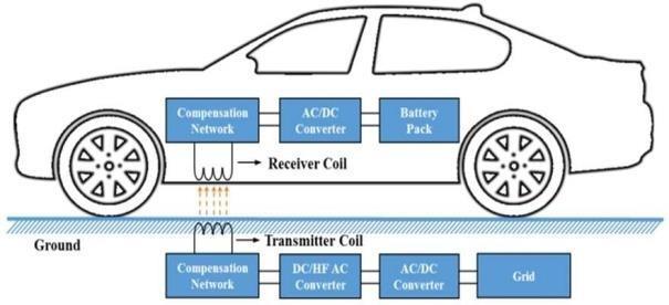
The main difference between a conductive charging system and a WPT charging method is that the transformer in the former system is replaced by a set of loosely magnetically coupled coils in the latter. The conductive charging method relies onmechanicalcontact between the EV and charge inlet.The cable can be fed froma charging station. Theconductive charging method can be categorized as an AC charging method and a DC charging method.AC conductive charging is carried out via AC charging. On the other hand, DC conductive chargingis carried out using a DC charger. It is known as fast DC charging. It uses up to 50kW, and the battery can be charged in 20min from empty to 80% full. The WPT charging method uses an electromagnetic (EM) field to transfer energy between two coils. Energy is transmitted through an inductive coupling to the electrical device. This energy is used to charge the batteries. For EV charging purposes, the WPT consists of many stages, as shown in Figure1. The charging station side consists of the following: (1) anAC/DC converter which converts AC utility power toDC power using a rectifier with a power factor correction, (2) a DC/high-frequency (HF) inverter
which converts DCpower tohigh-frequency ACpowerto drive the transmitter coil through a compensation network, and (3) a transmitter coilwhich generates an alternating magnetic field. The EV side consists of (1) a receiver coil which is coupled with an alternating magnetic fieldgenerated by the transmitter coil, (2) an AC/DC converter which rectifies the AC utility power to DCpower,and(3)abatterypackwhichischargedby the transmitted electricity energy. In this process, the transferred power and efficiency can be significantly improved by resonating with a compensation network.
Fig1. Structureofatypicalinductivepowertransfersystem forelectricvehicle(EV)charging.
B. WPTMethods
Since the introduction of wireless charging systems for EVs, four methods for the design of WEVCS have been utilized: traditional inductive power transfer (IPT), capacitive wireless power transfer (CWPT), magnetic gear wireless power transfer (MGWPT) and resonant inductivepowertransfer(RIPT).
Capacitive wireless power transfer: The low cost and simplicity of CWPT technology, using advanced geometric and mechanical structures of the coupling capacitors, is very useful for low- power applications, such as portable electronics devices, cellular phone chargers,androtatingmachinesbasedCPWT.
Magnetic gear wireless power transfer: Magnetic gear WPT (MGWPT) is relatively different to both the CWPT and IPT. In this method, two synchronized permanent magnets (PM) are positioned side-by-side in contrast to other coaxialcablebased WEVCS. Themainpower asthe current source is applied to the transmitter winding to produce a mechanical torque on the primary PM. With the utilizationof the mechanical torque, the primary PM rotates and induces a torque on the secondary PM through mechanical interaction. In two synchronized PMs, the primary PM works as the generator mode and
© 2021, IRJET | Impact Factor value: 7.529 | ISO 9001:2008 Certified Journal | Page1821
International Research Journal of Engineering and Technology (IRJET)
e-ISSN:2395-0056
Volume: 09 Issue: 08 | Aug 2022 www.irjet.net p-ISSN:2395-0072
the secondary PM receives power and delivers it to the batterythroughthepowerconverterandBMS.
Inductive power transfer: Traditional IPT was developed by Nikola Tesla in 1914 to transfer power wirelessly. It is based on severalEV charging structures. IPThasbeentestedandutilizedinawidevarietyofareas ranging from milliwatts to kilowatts to transfer contactlesspowerfromthesourcetothereceiver.
Resonant inductive power transfer: TheRIPTisoneof the most well-known and advanced versions of the traditional IPT, in terms of designing power electronics andwirelesstransformercoils.LikeotherWPTs,themain AC voltage is converted into the HF AC source and supplied to the transmitter or primary winding. The receiver or secondary coil receives power via varying magnetic fields. The received power is converted to DC for the battery bankof the EVs through additional power electronics and filter circuitry. In comparison to the traditional IPT, additional compensation networks in the series and/or parallel configurations are added to both the primary and secondary windings not only to create theresonantcasebutalsotoreduceadditionallosses.
C. WPTTopologies.
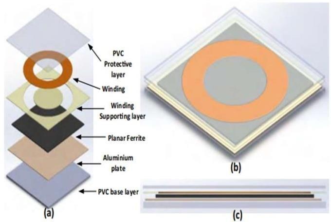
In the wireless charging systems, the transmitter and receiver pads are made of multiple component layers in order to gain maximum power transfer efficiency and lower electromagnetic interference with cost effectiveness. There are three main components of the wirelesstransformerpads:coil,shieldingmaterial(ferrite and aluminum plate), and protective and supportive layers.
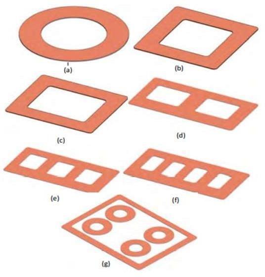
Coil shapes: In WCS for EVs, an air-core wireless transformer concept is used to transfer several watts to kilowatts of power from the source to receiver sides. As shown in Fig. 2, a variety of planar coil shapes such as circular, rectangular,andhybridarrangementshavebeen utilized in the wireless transformer designs to improve performance and to solve misalignment problems between the transmitter and receiver pads. Wireless charging coils are categorized in two main areas: polarized pads (PPs) and non- polarized pads (NPPs). Polarized pads are created from multiple coils and shape to generate perpendicular (vertical) and parallel (horizontal)
componentsoftheflux.
Fig:2WirelessTransformer(a)explodedview(b)Top view (c) Cross-section and Coil shapes(a)Circular(b)Square(c) Rectangular(d)DoubleD(e) Bi-polar (f) Double-D quadrature (g) Quad-Dquadrature
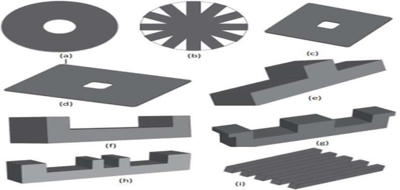
Magnetic ferrite shapes: Another important component of
thewirelesstransformerismagnetic ferritestructure.Inthe WEVCS, the magnetic flux is generated in medium to high power ranges. This would be high and there is a need to meet safety standards to avoid any health and safety issues. In addition, it affects coupling efficiency between two windings, particularly if there is no shielding to reduce the leakage fluxes. Proper design of magnetic ferrite cores can not only assist to redirect path to magnetic fluxes from primary to secondary, but also improve mutual inductance and self-inductance ofthe coils. The selection of ferrite core depends on multiple factors including size, shape, permeability,operatingfrequencyandcost.
International Research Journal of Engineering and Technology (IRJET) e-ISSN:2395-0056
Volume: 09 Issue: 08 | Aug 2022 www.irjet.net p-ISSN:2395-0072
Fig.3. Ferriteshapes(a)Circular(b)circularstriated(c) square (d) rectangular (e) T-core (f) U-core(G)E-core(h) Fig4. Basic diagram of dynamic wireless electric vehicle chargingsystem.
DoubleU(i)striatedblocks.
2. Static and Dynamic Charging systems.
Static wireless electric vehicle charging system (SWEVCS): WEVCS unlocks another door to provide auserfriendly environment for consumers (and to avoid any safety related issues with the plug-in chargers). Static WEVCS can easily replace the plug-in charger with minimal driver participation, and it solves associated safety issues such as trip hazards and electric shock. The primary coils installed underneath in the road or ground with additional power converters and circuitry. The receiver coil, or secondary coil, is normally installed underneath the EVs front, back, or center. The receiving energy is converted from AC to DC using the power converter and is transferred to the battery bank. In order to avoid any safety issues, power control and battery management systems are fitted with a wireless communication network to receive any feedback fromthe primary side. The charging time depends on the source power level, charging pad sizes, and air-gap distance between the two windings. The average distance between light-weight duty vehicles is approximately 150–300 mm. Static WEVCS can be installed in parking areas, car parks, homes, commercial buildings, shopping centers, and park ‘n’ridefacilities.
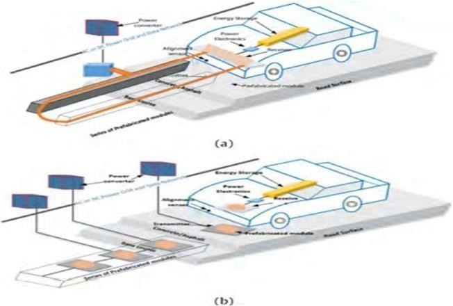
Dynamic wireless electric vehicle charging system (DWEVCS): Plug-in or BEVs are suffering due to two major obstacles-cost and range. In order to increase range, EVs are required to charge either quite frequently or to install alarger battery pack (which results additional problems such cost and weight). In addition, it is not economical to charge a vehicle frequently. The dynamic wireless electric vehicle charging system (D-WEVCS) is a promising technology, which can reduce the problems associated withrangeandcostofEVs.
It is the only solution for future automation EV. It is also known as a ‘‘roadway powered”, ‘‘on-line” or‘‘inmotion”WEVCS. As shown in Fig. 4, the primary coils are embedded into the road concrete at a certain
distance with high voltage, high frequency AC source and compensation circuits to the micro grid and/or RES. Like static-WEVCS, the secondarycoil is mounted underneath the vehicles. When theEVs pass over the transmitter, it receives a magnetic field through a receiver coil and convertsittoDCtochargethebatterybankbyutilizingthe power converter and BMS. Frequent charging facilities of EVs reduce the overall battery requirement by approximately20% incomparisontothecurrentEVs.For dynamic- WEVCS, transmitter pads and power supply segmentsneedtobeinstalledonspecificlocationsandpredefined routes. The power supply segments are mostly divided into centralized and individual power frequency schemes as shown in Fig. 4 (a) and (b). In the centralized power supply scheme, a large coil (around 5–10m) is installed on the road surface, where multiple small charging pads are utilized. In comparison with the segmented scheme, the centralized scheme has higher losses, lower efficiency including high installation, and higher maintenance costs. Overall, the installation of initial infrastructure for this technology would be costly. With thehelp of a self-driving car in future, it will help to create the perfect alignment between the transmitter and receiver coils which can significantly improve the overall power transfer efficiency. Dynamic-WEVCScan be easily incorporated in many EVtransportation applications, such aslightdutyvehicles,bus,rail,andrapidtransport.
© 2021, IRJET | Impact Factor value: 7.529 | ISO 9001:2008 Certified Journal | Page1823
International Research Journal of Engineering and Technology (IRJET)
e-ISSN:2395-0056
Volume: 09 Issue: 08 | Aug 2022 www.irjet.net p-ISSN:2395-0072
3. In-Wheel WPT System.
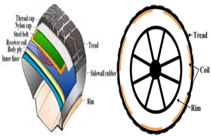
Stationary WEVCS already present some challenges, such as EMC issues, limited power transfer, bulky structures and higher efficiency. Furthermore, the power transfer efficiency depends on the coil alignment and air-gap distancebetweenthesourceandreceiver.Theaverageairgap distance varies from 150 to 300mm for small passenger vehicles while it may increase for larger vehicles. The alignment can be solved by utilizing sensing technology or parking assistance, which can guide the driver to find the center of the coil. Dynamic- WEVCS technology has to overcome two main hurdles, large airgap and coil misalignment, before it is more widely accepted. Due to the large number of source coils, the misalignment problem can be solved to some extent. In order to rectify air-gap problems in the WEVCS, in-wheel WCS (IW-WCS) has been developed for stationary and dynamic applications. It is also less dependent on any standardization receiving coil shape and locations,which have been suggested in research articles. Static and dynamicIW-WCS arefuturetechnologies thatcan be used to charge EVs or PHEVs while they are stationary or in motion. Due to lower air-gaps and higher coupling efficiencies between thetransmitter and receiver, IWWCS has significant advantages over the exiting quasidynamic or dynamic- WCS. Like other WEVCS, the multiple primary or source coils are normally installed under the road surface. Thebasic schematic diagram of IW-WCS for stationary and dynamic applications is presented in Fig 5. The main
grid source is converted to a high frequency (HF) AC source, which is connected to primary windings through a compensation circuit. Unlike other WEVCS, the secondary coils are installed into the tire structure in theIW-WCS. The air-gap between the source and receiver coils in IWWCS is smaller in comparison to the current static-or dynamic-WEVCS. The three main structural components in IW-WCS are the wireless transformer coils, power source, and internal structure of the tyre, which need to be designed carefully in order to achieve an efficient static-and dynamic-IW-WCS. Detailed internal placement of the receiver coils is demonstrated in Fig 5. Multiple receiver coils are placed ina parallel combination inside the tyre. The advantages of such an arrangement are that onlytheparticularreceiver coil thatisincontact withthe transmitter is activated. In some cases, when horizontal misalignment occurs, multiple receiver coils can be activated. These transfer power to the battery bank or load. Each receiver coil contains a resonant capacitor, rectifier, and filtering circuitry. The recommended location for the receiver coils array is between the steel belt and body ply. Table8 shows the specifications of transmitterandreceivercoilsutilizedintheIW-WCS.
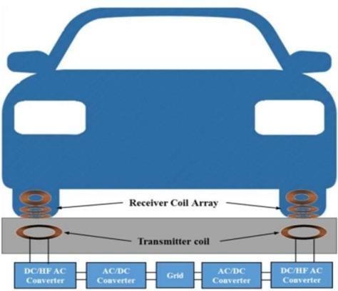
Fig5:Basicschematicdiagramofthein-wheelWPTsystem.
To understand magnetic field distribution and leakage
fluxes in the static or dynamic IW-WCS, FEM simulation was employed for an axisymmetric model of a 10 mm thick in-built steelbelt(IBSB)rubbertyreplus7mmairgap and17 mm air-gap with primary and secondary windings, as presented in Fig 6. At 100 kHz, the magnetic flux density and current density of the primary windings with the planar ferrite cores was generated where the magnetic permeability of the tyre was selected (because the rubber tyre has the same permeability as air in the magnetic field). The inbuilt steel mesh attracts some magnetic fluxes towards them due to the conductive material. As a result, it slightly
International Research Journal of Engineering and Technology (IRJET) e-ISSN:2395-0056
Volume: 09 Issue: 08 | Aug 2022 www.irjet.net p-ISSN:2395-0072
increases the leakage magnetic fluxes in the wireless transformer. The mutual inductance decreases between twowindingsandlowersthecouplingcoefficient(k)from 0.52to0.46forthe10mm thick tyrewith7mmair-gap. In addition, a Simulation was run with aluminum rim material, placed approximately 40 mm from the secondary coil inside the tyre, in order to understand the effect of the rim. The short circuit inductance (Ls) is reducedfrom45mHto35mH, which means thealuminum rim can reduce the leakage fluxes and improve the coupling. Overall, it helps to reduce the risk of health and safetyissuesforthedesignofWEVCS.
Fig7:Graphenebattery.
Fig6. In-Wheel WCS (a) internal coil placement (b)coilarrangement
4. Introduction to Graphene battery technology
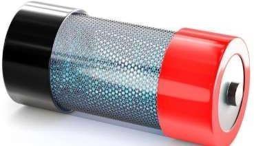
Introduction to grapheme batteries: The structure of graphene battery technology is similar to that of traditional batteries, where two electrodes and an electrolyte solution are used to facilitate ion transfer.The main difference between graphene-based batteries and solid-state batteries is in the composition of one or both electrodes.Thechangeprimarilyliesinthecathode,butit is also possible to utilize carbon allotropes in the anode. The cathode ina conventional battery is purely composed of solid- state materials, but a composite-a hybrid material containing a solid-state metallic material and grapheme is used as the cathode in a grapheme battery. Depending on the intended application, the amount of graphene in the composite can differ. The amount of graphemeincorporatedintotheelectrodeisusuallybased on the performance requirements and depends upon the existing efficiencies and/orweaknesses of the solid-state precursormaterial.
Graphene Battery Break through: The real grapheme battery break through are the graphene-lithium-ion hybrid chemistries incorporated into the cathodes of lithium-Sulphur cells as detailed in this guide. There are no pure graphene electrodes in agraphene battery, many graphene-based electrodes are fabricated and work in a similar wayto traditional batteries. Their performance is enhanced via the addition of grapheme to the electrode formulation. Generally, inorganic-based electrodes will have limitations which are typically surface area, density, capacity, cycle times, conductivity or capacitance to name a few. As graphene is a versatile molecule with many unique and desirable properties, it can be adopted in a varietyof ways as thereis no‘one size fits all’ solution for using graphene. Graphene isusedtoenhancemanyofthe benefits already present with traditional materials but it also helps to break through previous battery limitations, leading to increased battery performance or life. Graphene works in electrodes in two general ways, either as asupportor acomposite/hybrid. As a support material, graphene helps to keep metal ions in a regular order, which generally helps with electrode efficiency. As a compositematerialinanelectrode,itplaysadifferentrole as they are generally more involved in the facilitation of the charge itself, where its high conductivity and wellordered structure are critical to providing an improvementagainstitsnon-graphenepredecessors.
Graphene super capacitors: In the electronics field, super capacitors are a useful device capable of storing up more than a hundred times more energy than standard capacitors. They can also work in low temperature conditions and are regularly used as a replacement for electro chemical batteries. The ability to produce doubleelectric layers is one of the key properties of a super capacitance material, and is important in electric doublelayer capacitors (EDLC)super capacitors. Super capacitors store energy by building up charges at the electrodeelectrolyte interface through polarization. Activated carbon has been traditionally used as the electrode material, but the inability to work at high voltages is its major disadvantage. Graphene, and its derivatives, are useful due to their open-pore structure, high conductivity,high specific surface area, production potentialandlowcost;allofwhicharedesirableattributes forasupercapacitor.
International Research Journal of Engineering and Technology (IRJET)
e-ISSN:2395-0056
Volume: 09 Issue: 08 | Aug 2022 www.irjet.net p-ISSN:2395-0072
Graphene-Polymer Composite Electrodes Graphenepolymer composites do not have high conductivity comparedtoothergraphenebasedcomposites,butthey do possess a high doping- undoing capability, high charge/dischargerate,andflexibility.Graphene-polymer composites work by n and p doping redox reactions where electrons arelost or gained to convert and store energy. Graphene oxide and a nitrogen containing polymer are ideal to fabricate a graphene polymer electrode composite. Polymerization of the functional groups facilitates strong pi-pi interactions between the twocomponents of the composite, resulting in a large surface area and a semi-flexible structure that can mechanically deform during the cyclecharge- discharge processes. These graphene-polymer composites can exhibit up to 531 F g-1 and retain up to 74% of its capacitanceevenafter2000cycles.
Itisthethinnestmaterial known andwith that also the strongest.
Improved performance. Adding grapheme to battery electrodes increases the electrical conductivity, which improvesthebatteries'performance.
Sustainableandcost-efficient.
High-performancegraphemecomposites.
Fig8: Graphenebasedsupercapacitor.
Major advantages of graphene
Graphene-based materials have high porosity and greater surface area and are extremely strong and light weight.
Additionally, these materials possess high- charging capability and flexibility and are good conductors of thermal and electrical energy, which make them a suitablematerialtostoreenergy.
The high electrical conductivity of graphene increases the electrode density and accelerates the chemical reaction within the battery, which enables greater power transfer Graphene Batteriesin Electric Vehicles andfasterchargespeedswithlessheat.
Graphene also undergoes less degradation compared to lithium while delivering an improved performance, which prolongs the life span of EV batteries substantially. Moreover, grapheme batteries are also cost-efficient and sustainable compared to other EV batteries.
Inthefieldofbatteries,conventionalbatteryelectrode materials (and prospective ones) are significantly improved when enhanced with graphene. A grapheme battery can be light, durable andsuitable for high- capacity energystorage, aswellasshortenchargingtimes.
5. CONCLUSION
This paper presents a basic overview of the WEVCS for stationaryanddynamicapplicationswithcurrentresearched technology. In addition, a variety of core and ferrite shapes havebeendemonstrated,whichhavebeen utilizedincurrent wireless charging pad design. Also In- wheel Wireless charging method type is discussed that over comes the misalignment problems and air gap reduction. Also, the introduction of Graphene battery to EVs would increase the batterychargingefficiency.
REFERENCES
[1] Panchal, C.; Stegen, S.; Lu, J. Simulation of core shape considerations of wireless charging systemsfor electric vehicles. In Proceedings of the Powerand Energy Engineering Conference (APPEEC) IEEEPES Asia-Pacific, Brisbane, QLD, Australia,15–18November2015.
[2] Panchal, C.; Stegen, S.; Lu, J. Review of static and dynamic wirelessel ectric vehicle charging system. Eng. Sci.Technol.Int.J.2018,21,923–937.
[3] Covic, G.A.; Kissin, M.L.G.; Kacprzak, D.; Clausen,N.; Hao, H. A bipolar primary pad topology for EV stationary charging and high way power by inductive coupling. In Proceedings ofthe 2011 IEEE Energy Conversion Congress and Exposition, Phoenix, AZ, USA, 17–22September2011;pp.1832–1838.
[4] Maxwell, A. (2022, February 8). Graphene EV Batteries: How Far Away Are We?– Top Charger. Top Charger–EVCharger ReviewsandGuides.
[5] C, Iclodean.etal. Comparison of Different Battery Types for Electric Vehicles. IOP Conference Series: MaterialsScienceandEngineering2017