International Research Journal of Engineering and Technology (IRJET) e ISSN: 2395 0056

International Research Journal of Engineering and Technology (IRJET) e ISSN: 2395 0056
Manu K S1 , Dr. C Santhana Lakshmi2 , Dr. S Purushotham3 , Dr. V Shanmugasundaram4 , Dr. R Satheesh5
1Manu K S: Student, Dept. of EEE, SCT, Salem, Tamil Nadu, India 2Dr. C. Santhana Lakshmi (co author): Assist Professor (Sr Gd) Dept. of EEE, SCT, Salem, Tamil Nadu, India 3Dr. S. Purushotham (co author): Assist Professor, Dept. of EEE, SCT, Salem, Tamil Nadu, India 4Dr.V. Shanmugasundaram (co author): Assist Professor, Dept. of EEE, SCT, Salem, Tamil Nadu, India 5Dr. R Satheesh (co author): Assist Professor, Dept. of EEE, SCT, Salem, Tamil Nadu, India ***
Abstract - An in depth analysis of short circuits in power distribution systems for industry is presented. A power system short circuit study is performed to ensure the completeness of the equipment fault classification and to provide specifications for newly installed equipment to withstand the degree of short circuit that exists at each point in the system. Electrical systems Short circuit analysis helps ensure that personnel and equipment are protected, by establishing proper tripping ratings of the switches (breakers and fuses). If the extent of the system failure exceeds the interrupting capacity of the fault clearing device, the consequences can be severe. It can seriously threaten human life and cause personal injury, major property damage, fire, and costly downtime. In addition, the short circuit current obtained from the short circuit study is usedfortherelaycoordinationstudy.
Key Words: Short circuit, Analysis, Industrial distribution system,Electricalpowersystemstudy,Industry.
A short circuit study is performed to determine the magnitude of the potential current flowing in the power system at different time intervals after the fault has occurred. The amplitude of the current flowing in the powersystemafterafaultdifferswithtimeuntiltheyreach equilibrium.Thebehaviorisduetothecharacteristicsand dynamics of the system. During this time, a protection system is required to detect, interrupt and isolate these faults. The duty for the equipment depends on the magnitudeofthecurrent,whichdependsonthetimesince the onset of the fault. This is done for different fault types (three phase, phase to phase, two phase earth and phase to earth) at different locations in the system. The information is used to select fuses, circuit breakers and switchgearsizesinadditiontoprotectiverelaysettings.
Even the best designed electrical systems sometimes experience short circuits resulting in abnormally high currents. Overcurrent protective devices, such as circuit breakers and fuses, must safely isolate the fault from a
provided location with less damage to the circuit and equipment as well as less interference. for plant working procedures. Other system devices like cables, busbars and disconnecting switches, must be able to withstand the maximummechanicalandthermalstresscausedduetothe maximum short circuit current flowing through those devices. The amperage of the short circuit current is usually estimated by calculation, and the equipment is selectedusingtheresultsofthecalculation.
The current during a short circuit at any point in the system is limited by the impedance of the circuit and the source equipment or sources at the fault point. It is not directlyrelatedtothesizeoftheloadonthesystem.
However,additionstothesystemtoincreasetheability to handle growing loads, such as a larger or larger transformer from a utility, without affecting the normal load in some locations. Existing places within the system can crucially increase the short circuit current at these points. When an existing system is expanded or a new system is installed, the existing short circuit current must be determined in order to apply the appropriate overcurrentprotectiondevices.
Thecalculatedmaximumshort circuitcurrentisalmost always required. In some cases, minimum holding values arealsonecessarytoverifythesensitivityrequirementsof currentsensitiveprotectivedevices.
The scale and complexity of many modern industrial systems can make long term short circuit current calculations impractical. Calculators are often used for largeshortcircuitstudies.
Fullcalculationoftheshortcircuitcurrentswillgivethe currents as a function of time at the position of the short circuit from the beginning of the short circuit until its termination, corresponding to the instantaneous value of thevoltageatthebeginningtimeofshort circuitcurrents.
Volume: 09 Issue: 07 | July 2022 www.irjet.net p ISSN: 2395 0072 © 2022, IRJET | Impact Factor value: 7.529 | ISO 9001:2008 Certified Journal | Page2732
International Research Journal of Engineering and Technology (IRJET) e ISSN: 2395 0056
Volume: 09 Issue: 07 | July 2022 www.irjet.net p ISSN: 2395 0072
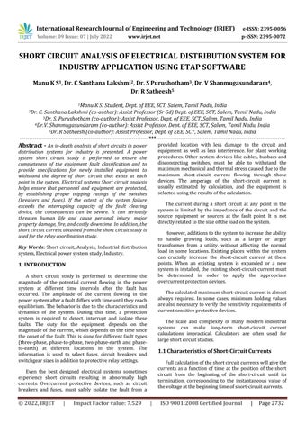
Short circuit faults are generally divided into symmetrical and asymmetrical types. These faults are further categorized into one of five categories. In order of frequencyofoccurrence,theyare:
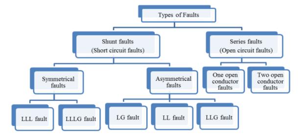
Ik ′′ =initialsymmetricalshort circuitcurrent
ip =peakshort circuitcurrent
Ik =steady stateshort circuitcurrent
id.c. =d.c.componentofshort circuitcurrent
A =initialvalueofthed.c.componentid.c.
Chart 1:Short circuitcurrentofafar from generator shortcircuitwithconstanta.c.component
In most practical cases, such a determination is not necessary. Based on the application of the results, it is interesting toknowthesymmetrical a.c.component r.m.s. value and the peak value ip of the short circuit current after the occurrence short circuit. The highest value ip depends on the time constant of the decaying aperiodic componentandthefrequencyf,thatisontheratioR/Xor X/R of the short circuit impedance Zk, and is acheived if theshortcircuitbeginsatzerovoltage.ipalsodepends on the reduction of the short circuit current symmetrical a.c. component.
Fig 1: Differenttypesoffaults
SymmetricalFaults:
These faults do not give rise to zero sequence or negativesequencecomponentsbecausetheyarebalanced, symmetrical faultsonlyconsists positivesequencevalues. This is type of fault is very dangerous in the electrical system, but it is not common. This type of defect is also calledasabalanceddefect.
Three Phase Line to Line Fault: The three phase fault occurs when phases R, Y and B are shorted togetherbutnotgrounded.

Three PhaseLine toGround Fault:Thethreephase togroundfaultsisafaultinwhichallthephases(R, YandB)areshort circuitedandgrounded.
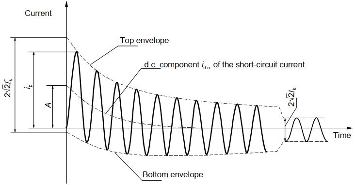
Ik′′ =initialsymmetricalshort circuitcurrent
ip =peakshort circuitcurrent
Ik =steady stateshort circuitcurrent
id.c. =d.c.componentofshort circuitcurrent
A =initialvalueofthed.c.componentid.c
Chart -2:Short circuitcurrentofanear to generator shortcircuitwithdecayinga.c.component
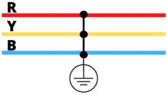
Fig 3: ThreePhaseLinetoGroundFault
Asymmetrical
Asymmetrical faults require separate calculation of the positive, negative and zero sequence components separately. Asymmetrical faults are more common and lessseverethansymmetricalfaults.
International Research Journal of Engineering and Technology (IRJET) e ISSN: 2395 0056
Volume: 09 Issue: 07 | July 2022 www.irjet.net p ISSN: 2395 0072
Single Line to Ground Fault: Line to Ground fault occurs when one of the phases (R, Y or B) is grounded.
4. Linetolinefault LL Unsymmetrical 15 20% 5. Doublelineto Groundfault LLG Unsymmetrical <10%

Line to Line Fault: This type of fault occurs when twophasesareshortcircuited(R Y,Y BorB R).

The fundamental frequency currents that flow during short circuits come from rotating machines. (Charged capacitors are capable of generating extremely high transient short circuit discharge currents, but they are equipped with a natural frequency much higher than that of the calculated power frequency. Short circuit working current does not increase appreciably by adding the dischargeofthecapacitor,calculatedasdescribedforRLC circuits in many electrical engineering books and the appropriate RLC circuit may be based on the electrical systemdata.)Rotatingmachineryinindustrialplantshort circuitcalculationsmaybeanalyzedinfivecategories:
Fig 5:
Line
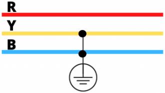
Double Line to Ground Fault: This type of fault occurswhentwophasesaregroundedtogether(R Y G,Y B GorB R G). Fig 6:
Synchronousgenerators
Synchronousmotorsandcondensers Inductionmachines Electricutilitysystems Adjustablespeedacinductionordcmotorswith solid stateacpowersupplyequipments
The fault current of each rotating machine source is limited by the impedance of the machine and the impedancebetweenthemachineandtheshortcircuit.The fault current is generally not dependent of the machine’s pre faultload.Theimpedanceofarotatingmachineisnot asimplevaluebutacomplexvaluethatchangesovertime.
The scope of the project includes the completion of Short Circuit Studies for various case studies of Industrial electricalpowerdistributionsystem.
Theobjectiveofashortcircuitstudyonapowersystem iscarriedouttoensureadequacyoffaultratingofexisting equipment and to achieve specifications of the new equipmenttobeinstalledtowithstandshortcircuitslevel availableateachpointofthepowersystem.
International Research Journal of Engineering and Technology (IRJET) e ISSN: 2395 0056
Volume: 09 Issue: 07 | July 2022 www.irjet.net p ISSN: 2395 0072
Ohm’s law, I = E/Z, is the basic relationship used to determine I, the short circuit current, where E is the source control voltage and Z is the source impedance at theshortcircuitpoint,includingsourceimpedance.
Most industrial systems have multiple short circuit supplies as each motor can contribute. One step in short circuit current calculation is to simplify the multiple sourcesystem,providedthatthebasicrelationisapplied.
The complexity of the system and equipment together with the lack of precise parameters make the precise calculation of the short circuit current extremely difficult, butextremeprecisionisnotnecessary.
The calculated maximum short circuit current value is used to select a breaker with an appropriate short circuit capacity,toverifytheabilityofpowersystemcomponents to withstand mechanical and thermal stress, and to determine coordination. current time of protection relay . The minimum values are used to set the required sensitivity of the protective relay. The minimum short circuitvaluesmostofthetimesareestimatedasfractions of the maximum values. Under this case it is enough to calculatethemaximumvalueoftheshort circuitcurrent.
To calculate the maximum short circuit current, the industrial electrical system should have the largest expectednumberofrotatingmachinesconnected(usually thesystemisatfullloadinthefuture).
An important part of preparing for the short circuit currentcalculationissettingtheimpedanceofeachcircuit element and converting the impedances so that they match each other for series and parallel connection. Sources of impedance values for circuit elements are the nameplates, manuals, manufacturer's catalog, tables contained in this chapter, and contact the manufacturer directly.
Two consistent forms are established to represent impedance as ohms and per unit (each differs by a percentage by a factor of 100). The impedance of an individual device is often given as a percentage, which facilitates comparisons, but percentage impedance is rarelyusedwithoutconversioninsystemcalculations.The unitformofimpedanceisusedbecauseitismorepractical than the ohmic form when the system contains multiple
voltagelevels.Impedancesexpressedperunitonadefined basiscanbedirectlymatched,regardlessofthenumberof voltage levels present from source to fault. For this convenience,thebasevoltageateachvoltagelevelmustbe tiedtotheturnsratiooftheconnectedtransformers.
There are four base quantities in the system of units: base apparent power in volt amperes, base voltage, base current, and base impedance. The relationship between the base per each unit and the actual quantities is as follows: Usually, an actual value is chosen for the fundamental apparentpowerinvolt amperes,andthebasevoltageata level is chosen to match the rated voltage of the transformeratthatlevel.Thebasevoltagesatotherlevels are then established by the transformation ratios of the transformer.Thebasecurrentandbaseimpedanceateach level are then obtained using standard relations. The following formulas apply to a three phase system where thebasevoltageisthelinevoltageinvoltsorkilovoltsand the basic apparent power is the three phase apparent powerinkilovolts ampereormegavolt ampere: ) ) √ ) √ ) √ ) ) √ ) ) √ ) ) ) ) ) )
Impedance of individual power system elements is usually obtained in the form of a conversion to the relevantbasesforcalculationperunit.Theimpedanceofa cableis usuallyexpressedinohms.Convertingtoperunit using the indicated relationships leads to the following simplifiedformulas,wheretheper unitimpedanceis Zpu : ) ) ) ) )
Transformer impedance is a percentage of self cooling transformerratinginkilovolt ampsandisconvertedusing thefollowing: ) )
International Research Journal of Engineering and Technology (IRJET) e ISSN: 2395 0056
) )
Motor reactance can be obtained from boards that provide unit resistance above the element rating in kilovolt ampsandconvertedusingthefollowing: )
The procedure for calculating the short circuit current ofanindustrialsystemincludesthefollowingprocedures: Preparesystemdiagrams. Collectandconvertimpedancedata. Combineimpedances. Calculateshort circuitcurrent.
The calculation of the maximum and minimum short circuitcurrentsisbasedonthefollowingsimplifications.
During the short circuit there is no change in the type ofshortcircuitinvolved,i.e.,athree phaseshortcircuit remains three phase and a line to earth short circuit remainsline to earthduringtheshortcircuit.
The impedance of the transformers is referred to the tap changer in main position. This is admissible, because the impedance correction factor KT for networktransformersisintroduced
Arcresistancesarenottakenintoaccount
All line capacitances and shunt admittances and nonrotating loads, except those of the zero sequence system,areneglected
Althoughtheseassumptionsarenotstrictlytrueforthe electrical systems under consideration, the result of the calculation meets the objective that results are generally acceptedwithadmissibleaccuracy.
This is the voltage correction factor (commonly known astheC Factor).TheC Factorisusedtochangethedevice impedanceandthedrivingpointvoltage.TheIECsuggests calculations for minimum and maximum short circuit currents. Selecting C Factor for Max or Min activates the desiredtypeofcalculation.Wecandocalculationsforjust eitheroneatanytime.TheC Factorsvariesatthevoltage levels.
TABLE 2: VOLTAGEFACTORCTABLEASPERIEC 60909
VoltageCFactor
VoltageLevel Cmax Cmin
LowVoltage(<1kV) 1.05 0.95
HighVoltage(>1kV) 1.1 1
When calculating the maximum short circuit current, thefollowingconditionsmustbetakeninaccount:
The voltage factor Cmax according to Table 2 must be considered to calculate the maximum short circuit current
Select the system configuration and the maximum contribution of power plants and network feeders leading to the maximum value of short circuit current at the short circuit location, or for an acceptable networktocontroltheshort circuitcurrent
When the equivalent impedance ZQ is used to represent the external network, the minimum equivalent short circuit impedance corresponding to the maximum contribution of the short circuit current ofthenetworkpowersuppliesshallbeused
Motorsshallbeconsidered
ResistanceRLoflines(overheadlinesandcables)is to beconsideredatatemperatureof20°C.
When calculating the minimum short circuit currents, thefollowingconditionsmustbetakeninaccount:
The voltage factor Cmin for the calculation of minimum short circuitcurrentsshallbeconsideredaccordingto table2.
Select the system configuration and the minimum contribution of power plants and network feeders resultingintheminimumvalueofshort circuitcurrent attheshort circuitlocation
Motors shall be not considered
Line Resistance RL(overhead lines and cables, line conductors and neutral conductors) must be introducedatahighertemperatures [ )]
Volume: 09 Issue: 07 | July 2022 www.irjet.net p ISSN: 2395 0072 © 2022, IRJET | Impact Factor value: 7.529 | ISO 9001:2008 Certified Journal | Page2736
International Research Journal of Engineering and Technology (IRJET) e ISSN: 2395 0056
Volume: 09 Issue: 07 | July 2022 www.irjet.net p ISSN: 2395 0072
Where
RL20 istheresistanceatatemperatureof C; is the temperature of the conductor in degrees celsius at the end of the short circuittime;
α is a factor equal to 0.004/K, valid with sufficient accuracy for most practical applications for copper, aluminium and aluminiumalloys.
Misc Power DB and Lighting transformer, which is furtherconnectedtoMainLightingPanel.
Total Connected Load of plant is 2285 kW. During the summerandwinterseasontheoperatingLoadofplant is 1823 kW and 1660 kW, Since the summer load contribution is significantly higher it is considered for Systemstudy.
These Sub Distribution boards are further providing supplytovariousStaticloadsandMotorLoads.
Facility is receiving Grid supply from Electricity Authoritythrough11kV300Sq.mmXLPECable.Cable is terminated at 11 kV ICOG panel located near plant gate by electricity board. From 11 kV ICOG Panel power is supplied to 3 Panel 11 kV Switchboard with extensiblebusbarlocatedatMainSubstationHTroom.
Both Transformers T1 and T2 both are rated at 1250 kVA, 11/ 0.433 kV connected between 3 panels 11 kV Switchboard and Main LT SWBD. Main LT Switchgear with short circuit rating of 50 kA is provided with extensiblebusbarboththesides.
FiveDG‟s,3of1010kVA,oneof40kVAandoneof250 kVA are connected to Main LT Switchboard. Sub Distribution Boards (SDB) located at load centres are connectedtotheMainLTSwitchboardthroughcables.
The ETAP software (is a proprietary software of Operations Technology Incorporated, California, USA) is used for Short Circuit Study. The Single Line Diagram is created in ETAP with the system data and the fault currentsdeterminedatvariousbuses;thesefaultcurrents areusedfortherelayco ordination.
The three phase short circuit currents and earth fault currents are calculated on the basis of source impedance, transformer impedance, generator impedance and cable positive sequence impedances, up tothelocationoffault.
TheshortcircuitstudyiscarriedoutasperIEC 60909 standard.
Main LT Switchboard is divided into four sections; Section 1 Section 2, Section 3 and Section 4. These sections are interconnected by Bus couplers namely Buscoupler 1,BusCoupler 2andBusCoupler 3.
Main LT Switchboard Section 1 is getting supply from Transformer T1 and DG 1. From Section 1, outgoing feeders to SDB like HVAC Panel, Utility process Panel, Fire Fighting Panel, WTP Panel, Power Panel, Process Panel, 250 kVAR Capacitor Panel 1 and UPS DB are provided
Impedance values of transformers are as per transformernameplates.Asthesearetestedvalues,no negative tolerance is considered for the short circuit studies.
80% of the LV load is considered as motor load to calculatemotorcontribution.
Method C is adopted for carrying out short circuit study in meshed networks as recommended by IEC 60909 Part 0.
Main LT Switchboard Section 2 is getting supply from DG 2.
The following are the „C‟ factors (Voltage Factor) considered for various system voltages. As per IEC 60909 Part 0. „C‟ factor accounts for variations in system voltage during operation, changing of transformer taps, sub transient behaviour of generators and motors etc.
H.V = 1.1
L.V = 1.05
Main LT Switchboard Section 3 is getting supply from TransformerT2andDG 3.Itisprovidingsupplyto250 kVAR Capacitor Panel 2, Utility Panel and Main LightingPanel.
Main LT Switchboard Section 4 receives power from DG 4&5.Section4isprovidingsupplytoUtility Block
Shortcircuitstudiesarecarriedoutfortwocaseseither anyoneofthesetwooperatingcaseswillbeutilizedunder anycircumstances.Thefollowingarethecasestudies:
2022, IRJET | Impact Factor value: 7.529 | ISO 9001:2008 Certified Journal | Page2737
International Research Journal of Engineering and Technology (IRJET) e ISSN: 2395 0056
Case 1: Phase Fault Study with Grid Supply (Both transformers feeding without being paralleled and All DG’sinoffcondition)
Case 2: Earth Fault Study with Grid Supply (Both transformers feeding without being paralleled and All DG’sinoffcondition).
Case 3: Phase Fault Study with Generator Supply (Three DG’s (1010 kVA) operating in parallel and Transformersinoffcondition).
Case 4: Earth Fault Study with Generator Supply (Three DG‟s (1010 kVA) operating in parallel and Transformersinoffcondition) TABLE 3: MAXIMUMFAULTCURRENTS
FROM
M
CURRENT (kA) 1. 11kVMeteringcubicle 1.137
3panel11kVHTSWBD 1.137
MainLTS/bSec 1 46.772
MainLTS/bSec 2 46.772
MainLTS/bSec 3 46.772
MainLTS/bSec 4 46.772
HVACChillerPanel 21.384
HVACPumpPanel 6.813
Substation250kVAR Capacitorpanel 1 31.721
Utility Process 1Panel 6.004
FireFightingPanel 2.905
WTPPanel 5.535
AdminBlockPower Panel 10.403
UPSI/CPanel 8.565
UPSO/GPanel 0.412
UPSDB 37.609
Process 2panel 14.483
70kVACapacitorPanel 13.116
CompressorIso.panel 15.125
SMDUPS20kVA 7.583
180kVARCapacitor 18.265
Panel 22. Substation250kVAR CapacitorPanel 2 34.716 23. Process 3UtilityPanel 6.267 24. Process 3Smallpower panel 4.096 25. Process 3AHU1Panel 2.808 26. Process 3AHU2Panel 2.29 27. Process 3AHU3Panel 1.876 28. Process 3UPSPanel 29. FiltermakingPanel 1.155 30. STPPanel 1.421 31. MainLightingPanel 19.468 32. LPProcess 2 2.961 33. LPProcess 3 3.921 34. LPAdminblock 2.654 35. EmergencyPanel 5.942 36. AdminIncomer 0.85 37. SMDTPDB 0.877 38. UtilityBlockMiscPower Panel 13.165 39. MCCPumpPanel 6.03 40. FuelTransferPanel 3.82
Short Circuit Analysis for the selected Single line diagram of over 40 bus was performed for various case studies using Etap software and the outcome has been listed for various case studies. All the equipments rating likeBus barratings,Circuitbreakerratings,Cable ratings, were evaluated and all the equipment was found okay to withstand maximum short circuit current(as listed in Table III), hence these equipments can be allowed to continuetheiroperation.
Theresultsofshortcircuitstudiesareusefulinorderto determine system configuration, system voltage levels, protection equipments, switchgears, and cables size, transformers,groundingandearthing.
ShortcircuitcurrentcalculationwasperformedasperIEC 60909. We can conclude the values of maximum short circuit current and minimum short circuit current can be
Volume: 09 Issue: 07 | July 2022 www.irjet.net p ISSN: 2395 0072 © 2022, IRJET | Impact Factor value: 7.529 | ISO 9001:2008 Certified Journal | Page2738
International Research Journal of Engineering and Technology (IRJET) e ISSN: 2395 0056
Volume: 09 Issue: 07 | July 2022 www.irjet.net p ISSN: 2395 0072
utilized for the further study of Relay/ Release co ordinationstudies.
IEC 60909 0; Short circuit currents in three phase a.c. systems Part0:Calculationsofcurrents
IEC 60909 1; Short circuit currents in three phase a.c. systems Part 1: Factors for the calculation of currentsaccordingtoIEC60909 0
IEC 60909 2: Electrical equipment Data for short circuit current calculations in accordance with IEC 909(1998)
IEC 60909 3; Short circuit currents in three phase a.c. systems Part 3: Currents during two separate simultaneous single phase line to earth short circuit currentsflowingthroughearth.
IEEE 399; Recommended practice for Industrial and CommercialPowerSystemsAnalysis
IEEE 141; Recommended practice for Electric Power DistributionforIndustrialPlants.
IEEE 241; Recommended practice for Electric Power SystemsinCommercialbuildings
IEEE 242; Recommended Practice for Protection and Coordination of Industrial and Commercial Power Systems
Stagg and A.H. El Abiad, "Computer Methods in Power System Analysis", Mcgraw Hill, 13th print, New Delhi,1988
William D. Stevenson "Elements Of Power System Analysis", McGraw Hill, Fourth edition, New Delhi, 1982
GeorgeL.Kusic,"ComputerAidedPowerSystemAnalysis", Prentice Hall,International,N.J.,NewDelhi,1989.
J. Arrilllaga, C.P. Arnold and B.J.Harker ,"Computer ModelingofElectricalPowerSystems",JohnWileyand Sons,1983.
Jin Yang (2011),Short Circuit and Ground Fault Analysis andLocationinVSC BasedDCNetworkCables,IEEE
SHORT CIRCUIT ANALYSIS BY USING MIPOWER Pranshu Shrivastava,ShwetaSahuModi,PoojaShrivastavaPro term Lecturer in Electrical department of IITM Gwalior Asst Prof in Electrical department of IITM GwaliorProtermLecturerinMathsdepartmentofITM University Gwalior International Journal of Engineering Research and Applications (IJERA) ISSN:
2248 9622 International Conference On Emerging Trends in Mechanical and Electrical Engineering (ICETMEE 13th 14thMarch2014).
Khan, R.A.J.; Junaid, M.; Asgher, M.M., "Analyses and monitoring of 132 kV grid using ETAP software," Electrical and Electronics Engineering, 2009. ELECO 2009. International Conference on , vol., no., pp.I 113,I 118,5 8Nov.2009
Bollen,M.HJ,"Methodforreliabilityanalysisofindustrial distribution systems," Generation, Transmission and Distribution, IEE Proceedings C , vol.140, no.6, pp.497,502,Nov1993
P. Kundar, “Power System Stability and Control”. New York:McGraw Hill,1994
© 2022, IRJET | Impact Factor value: 7.529 | ISO 9001:2008 Certified Journal | Page2739