International Research Journal of Engineering and Technology (IRJET) e ISSN: 2395 0056

Volume: 09 Issue: 06 | Jun 2022 www.irjet.net p ISSN: 2395 0072
International Research Journal of Engineering and Technology (IRJET) e ISSN: 2395 0056
Volume: 09 Issue: 06 | Jun 2022 www.irjet.net p ISSN: 2395 0072
Tejas Garud, Nitin Babar, Vaibhav Fasale, Alisha Salve
Dept. of Mechanical Engineering, Savitribai Phule Pune University, India Guide Name: Prof. J. P. Hugar & Prof. S.A Dahake ***
Abstract- In the forging industry, one of the main challenges is the reduction of setup change time which is non-productive time on the forging press. Long non-productive time reduces efficiency and affects profitability of the forging companies. In this thesis study, firstly setup change activities on the 1000 ton forging press of a forging company are observed and analyzed. With the help of these observations, it is seen that the new die holders with cassette holders and the new cassettes are required to reduce the setup change time radically. Different design versions of the new die holders have been studied. A new pair of die holders is designed and manufactured along with the new cassette holders and the new cassettes which hold the forging dies. The factors related to internal setup change operations, which are identified during the time and motion studies and root cause analysis, have been considered during design of the new die holder system.
Keywords: Hot Forging, Die Exchange, Die Exchange Time, Die Holder
Thedifficultiesinreducingsetuptimeonallforgingpresses exist primarily in the die holder, the clamping mechanism used,theassemblysequenceofthepartsfittingtogether,and thetrainingofworkerstofollowtheprocedurecarefully.On the1000tonforgingpress,thecurrentsetupactivitiestake approximately2to3hourswhilethepressiskeptidle,which isthetimewhenthepressisnotproducingacceptablequality parts. This directly increases the cost of forging and ultimately the parts being produced. Table no.1 shows the initialtimestudyforsetupchangeofatypicalparton1000 ton forging Press. One way to reduce the setup time is by applyingthetechniquecalledSingleMinuteExchangeofDies (SMED) which aims to perform setup operations within a single digit value of time in minutes. Together with quick changeover(QCO)technique,SMEDsignificantlytackleswith mostoftheupfrontproblems,therebyreducingconsiderable amountofsetuptime.
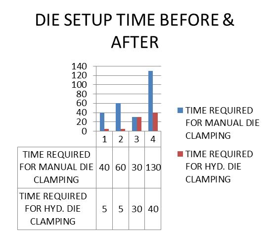
Table 1: DieSetupTimeforManualClamping
Operation No. Operation press Time in Min.
1 Dis MountingPrevious Die Set Off 40
2 MountingNewDie Set Off 60
3 HeatingDies Off 30
4 Total= 130
To minimize the time required for die clamping and to overcometheproblemoffasteningplatewearegoingto usehydraulicclamping.
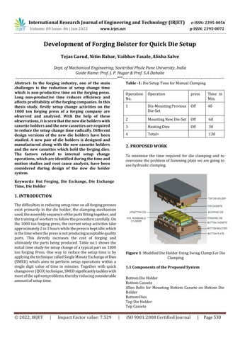
Figure 1:ModifiedDieHolderUsingSwingClampForDie Clamping
1.1 Components of the Proposed System
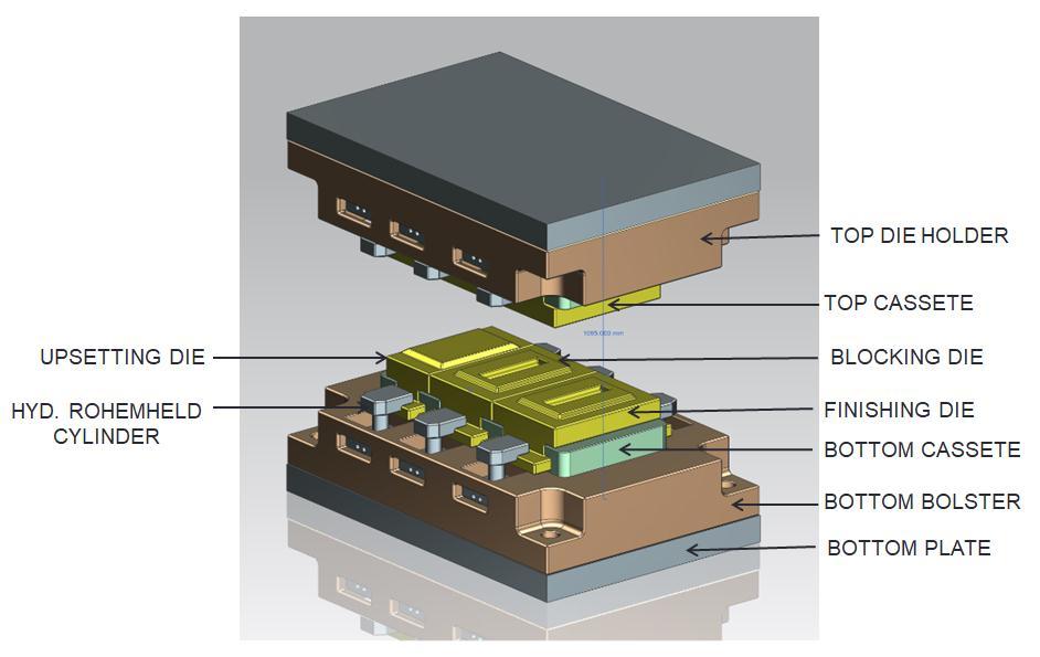
BottomDieHolder
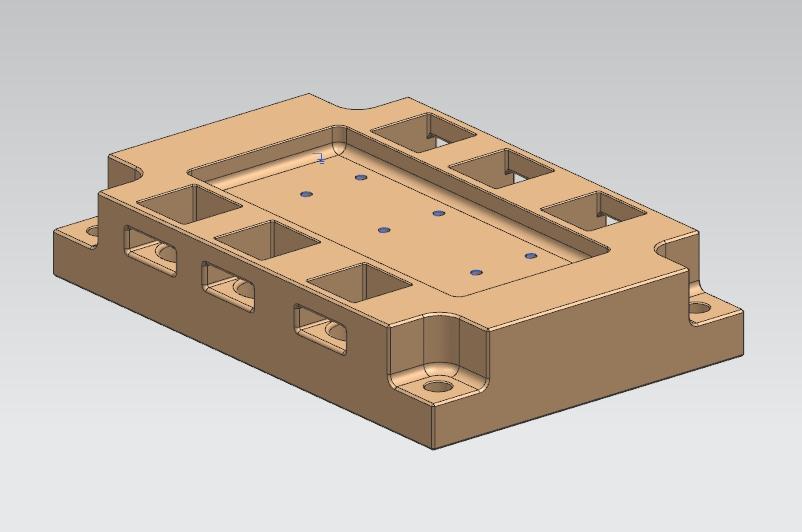
BottomCassete
Allen Bolts for Mounting Bottom Cassete on Bottom Die Holder
BottomDies
TopDieHolder
TopCassete
International Research Journal of Engineering and Technology (IRJET) e ISSN: 2395 0056
Volume: 09 Issue: 06 | Jun 2022 www.irjet.net p ISSN: 2395 0072
HydraulicPowerPack ElectricPanel
Thebottomdieholderisapartwhichisfixedtothebedof the forging press with the application of the Allen bolt. Thesedegreesoffreedomofbottomdieholderarelocked in all the sides. Because while forging it should not be movedfromitsfixedposition.
On the bottom die bolster cassette is mounted with the applicationofAllenbolt.Thedegreesoffreedomofbottom cassettemustbelockedfromallthesides.Thefunctionof bottom cassette is to hold the bottom dies in bottom
bolster.
Similarlytopdieholderisapartwhichisfixedtotheram of the forging press. This part is fixed to the ram of the press by the application of Allen bolt. The all degrees of freedomoftopdieholderarelockedbecauseitmustnotbe movedfromitsfixedpositionwhileforging.
Top cassette is mounted on top die holder with the applicationofAllenbolt.Degreeoffreedomofcassetteis lockedfromallthesidestolockthemomentwhileforging. Top cassette is used to mount the top dies on top die holder.
Thereare three top andthree bottom diesfor upsetting, Finishing, & blocking operation. These three dies are mounted in a bottom cassette on bottom die holder and three dies are mounted in a top cassette on a top die holder.
Therohemheldcylinderisahydraulicoperatedcylinder. Thesemainadvantagesofthesecylinderitconsistclamp whichisswingoperated.Thisisusedtosavetheareaand materialintop&bottomdieholder.
Thesecylindersareconnectedtothehydraulicpowerpack bytheapplicationofsteelpiping.
The electric panel connection is established to the hydraulicpowerpack whichisthen operated by electric switchprovidedonelectricalpanel.
Toloaddiesinthebolster.Theoperatorfirstliftsthedies fromgroundalongwithcassetteandputitintoabottom dieholderwiththeapplicationoftrolleyorforklift.
Whenoperatorpressthebuttononelectricpaneltoclamp the dies the hydraulic power pack increases the oil pressureintherohemheldcylinderfixedatthefrontoftop &bottomdies.
The swing clamp of this rohemheld cylinder is then clamping the dies mounted in a cassette at a hydraulic pressure of 350bar. This pressure is necessary and calculatedtoclampthedieson1000Toneforgingpress
Similarlywhenoperatorhastode clampthedies.Heorshe presses the button on electric panel. As soon as the operator presses the button the pressure in hydraulic cylinderisdroppedandclampreleasethedies.
2.1
Due to impact loading stress is generating in bottom die holder
International Research Journal of Engineering and Technology (IRJET) e ISSN: 2395 0056
To calculate stress caused by impact loading we have formulae
Duetotheimpactloadingcrushingstressisgeneratingin bottomdieholder.
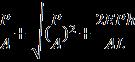
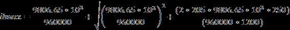
To calculate stress caused by impact loading we have formula, ∂max= Where,
P=LoadfallingdownN/ A=Crosssectionalarea
E=Young’sModulusofmaterialN/ h=Heightfromobjectfallmm
Given: P= A=L*W =1200*800 =960000
E=205Gpa h=250mm MaterialUsed=Din2714
FactorofSafety= = FOS = 30.63
Hencedesignofbottomdieholderaswellastopdieholder issafe.
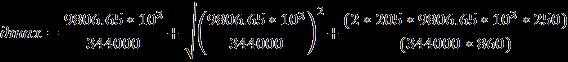
2.2 Bottom Cassete & Top Cassete:
Due to impact loading crushing stress is generating in bottomdieholder.
Tocalculatestressincasseteduetoimpactloading.
∂max= Given
P= A=860*400 =344000
E=205Gpa h=250mm
FactorofSafety= = FOS = 13.60
Hencecassetefortopandbottomissafe.
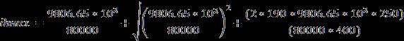
2.3 Bottom Dies & Top Dies: ∂max=
Volume: 09 Issue: 06 | Jun 2022 www.irjet.net p ISSN: 2395 0072 © 2022, IRJET | Impact Factor value: 7.529 | ISO 9001:2008 Certified Journal |
International Research Journal of Engineering and Technology (IRJET) e ISSN: 2395 0056
Givenmaterial=H11 P= A=400*200 =80000 E=190Gpa h=250mm
FactorofSafety= = FOS = 3.57
Hencediedesignissafeforbothtopandbottomdie.
In this study, die holder designed to suit hydraulic die clamping system which reduces idle time of the forging press has been designed, produced and tested. The die changing and adjustment operations with the proposed modulardiesystemhavebeenmuchsimpler,muchquicker andmoresystematicthantheoldchangeovermethods.The currentproblemsencounteredduringdiechanging.Inthis thesis, applicability of SMED System to 1000 ton forging presshasbeenstudied.
Theinternaldiechangingtimes,whicharetheunproductive timesofthepress,weregenerally2hours(130minutes)by theoldsystem.Inthetimestudyfortheparticularcase,the total time spent for internal die changing operations was 130 minutes by the system of the company. It has been reducedto40minutesbythenewsystem.Asavingof 90 minuteshasbeenobtained.Thereforethereductionis70%.
Table
Operation No. Operation press Time in Min.
1 Dis MountingPrevious Die Set Off 05
2 MountingNewDie Set Off 05
3 HeatingDies Off 30
4 Total= 40
Chart 1:DieSetuptimecomparisonformanual& ProposedSystem
[1]CarlGissing,“TheBookofForging”,SchifferPublishing Ltd,(2019)
[2] P. E. Fisher, “Selection of Engineering Material and Adhesives”CKCPress,(2019)
[3]N.S.Salunke&A.M.Ekatpure,”MechanicalEngineering Materials”,Tech Knowledge,(2018 19)
[4]InternationalTextbookCompany,“ForgingOperations”, (2018)
[5]VinodThombarePatil,Mrs.SnehalMucchala&Kishor Kumar, “Design of Machine Element”, Nirali Prakashan, (2017)
[6] Sunil Deshpande & Gautam Narawade,”Material Science”,Techmax,(2016 17)
Volume: 09 Issue: 06 | Jun 2022 www.irjet.net p ISSN: 2395 0072 © 2022, IRJET | Impact Factor value: 7.529 | ISO 9001:2008 Certified Journal
International Research Journal of Engineering and Technology (IRJET) e ISSN: 2395 0056
Volume: 09 Issue: 06 | Jun 2022 www.irjet.net p ISSN: 2395 0072
[7] Indrajeet M. Jain, “Strength of Material”, Techmax, (2015)
[8] S. K. Hajra Choudhary, A. K. Hajra Choudhary, Nirjhar Roy,“WorkshopTechnology”,(2010)
[9] Andrew Scotchmer, “5’S Kaizen in 90 Minutes”, ManagementBooks2000Ltd,(2007)
[10]www.forging.org
© 2022, IRJET | Impact Factor value: 7.529 | ISO 9001:2008 Certified Journal |