International Research Journal of Engineering and Technology (IRJET) e ISSN:2395 0056

Volume: 09 Issue: 05 | May 2022 www.irjet.net p ISSN:2395 0072
International Research Journal of Engineering and Technology (IRJET) e ISSN:2395 0056
Volume: 09 Issue: 05 | May 2022 www.irjet.net p ISSN:2395 0072
1
Abstract - The main function of differential is to provide Torque & RPM differentiation depending upon characteristics of different differentials. Goal of this project is to design a differential for significant weight and performance gains and also maximize and improvetraction utilization for a high performance race car. Differential torque biasing is influenced by a number of factors, including clutch packs, preload, ramp angles adjustments. Thefundamentalparametersforthisprojectisacquiredand bound by the rules and regulations specified for a fsae vehicle. Using Design Methodology, a cad model was developed which was then analyzed on suitable FEA software.
Key Words: LockedDifferential,OpenDifferential,Limited Slip Differential, Clutch Plate Type LSD, Vehicle Dynamics, RaceCar
Whentakinga corner naturallytheoutsidewheel tracesa longerdistancethantheinsidewheel.Sincespeedisequal to the distance traveled divided by the time it takes to go that distance; the wheels that travel a larger distance travelatahigherspeedandsotheoutsidewheelmustspin faster. And this is the reason as to why almost every car hasoneormoredifferentialsintheirdriveline.
Thedifferentialisasetofbevelgearsthattransmitsengine power to the wheels while allowing splitting of the enginetorquetwo ways, allowing each output to spin at a differentspeed.
Mechanicaldifferentialsaredividedintothreecategories:
1. LockedDifferential Spool
2. OpenDifferential
A spool is a simple axle with locked differential that basicallycouplesthetworearwheelssothatbothwheels areforcedtorotateatthesameangularvelocity.Thespool isextremelylightweightandhashigh reliabilityduetoits mechanicalsimplicity.Runningaspoolhoweverhassome drawbacks; specially, during cornering (more prominent at low speeds) the vehicle would experience understeer i.e. where the car turns less than it is expected to. This is becauseavehiclewithspoolwillwanttofightagainstthe directionofsteeringsincebothdrivenwheelsarepushing forward with equal force. The effects are accelerated tire wear,increasedpowerconsumption,andgreatersteering effort.
The open differential isuniversallyadopted on passenger cars to address this cornering issue of a spool by decouplingtheangularvelocitiesofthedrivewheels.The opendifferentialusinganarrangementofbevel gearscan deliver torque to both wheels that are free to rotate at differentvelocities Sincein thiscasethetorqueisalways equal on both sides torque transmission has no direct impact on vehicle handling, cornering balance, or driver inputs. However a traction problem is encountered if slippingeveroccurs.Itwillsendthemajorityofthepower to the slipping wheel the moment a wheel loses traction and so the car is not pushed forward when it is experiencingwheelslip.
Toovercomethisdownsideofspoolandopendifferential, Self Locking or Limited Slip Differential is used. A passive limited slip differential is based on mechanism in which somesortofclutchpacksandrampanglesinparallel with an open differential is used which offers the potential to cover the entire working range between the open
International Research Journal of Engineering and Technology (IRJET) e ISSN:2395 0056
Volume: 09 Issue: 05 | May 2022 www.irjet.net p ISSN:2395 0072
differential and the spool. It can be quite effective for racing cars, solving the traction problem on one side and improvingvehiclebalanceandstabilityonotherside.
The two most common types of passive LSD’s are Speed sensitivedifferentialandtorque sensitivedifferential.
As name suggests, the locking torque is a function of the angularvelocitydifferenceacrossthedifferential.Atypical device consists of open differential and rotary viscous coupling, basically a clutch pack immersed in a silicon based fluid. The system affects vehicle maneuverability to a limited extent. As building up a speed difference takes timethereiscertaindelayinthetorquetransferresponse thus for high performance applications this device is not verysuitabletoimprovevehiclehandlingandstability.
The most common torque sensitive device on road going sports cars and racing cars is the Clutch Plate type (Salisbury) Differential or Plated Differential. Though this differential is much more complex we find the adjust ability of the plated LSD a big upside in a motorsports application.
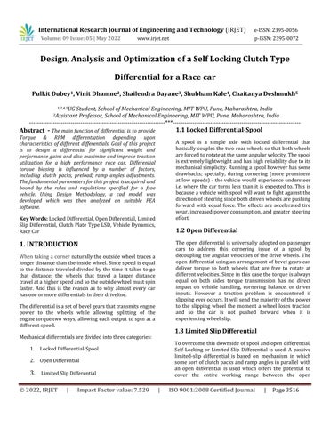
Upon acceleration, the spider axle is wedged into the inclined surfaces called ramps of the side gear pressure rings, with a component of the resultant force in such a way that it pushes those outwards and compresses the clutch plates. As the pressure increases and so larger friction on the clutch plates increasingly binds the driven wheelsasmoreaccelerationisappliedmakingitveryhard for them to spin at different rates. So ramp angles determine how much pressure is applied to the clutch plate to increasingly bind the wheels. The shallower the ramp angle, the more aggressive the locking characteristics. For example, a 45 degree ramp angle will lock up more aggressively than a 60 degree ramp angle, whilst a 90 degree ramp angle will not show any locking characteristicsatall.
Smaller the ramp angle, more spool like behavior we will observe for higher powered vehicles during acceleration. In this case, it limits the slip to a greater extent sending power to the wheels with good traction. But then car will experiencemoreundersteer.
On the coast side, larger locking inducesbetter braking stability, however, this also comes at the expense of understeerduringbraking.
Hence, finding the perfect spot for acceleration as well as coastrampanglesiskey.
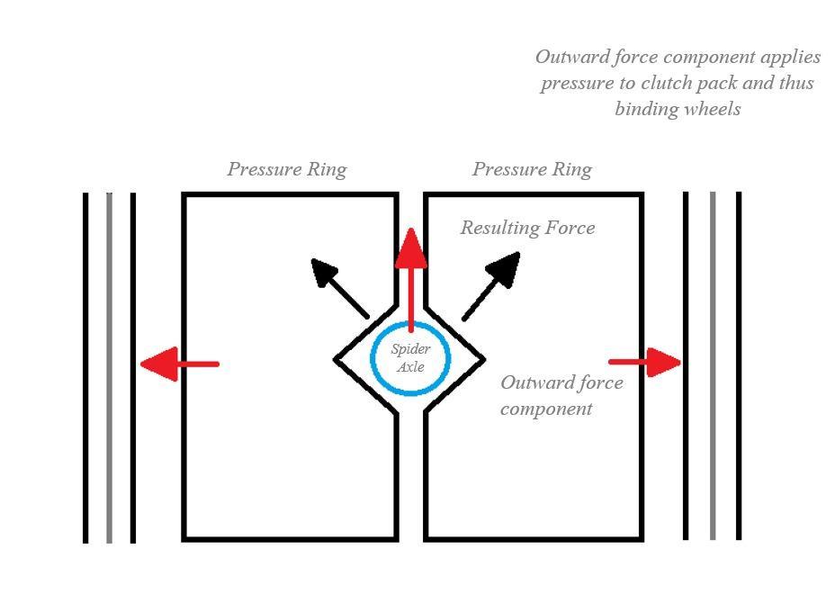
Basedonthebehaviour oftheLSDunderaccelerationand braking,wehavethreedifferentchoicesnamely1way,1.5 way, and 2 way. A 1 way differential only locks in acceleration,whilea2 waydifferentiallocksequallyunder acceleration or braking. For a 1.5 way differential, the ramp angle on the acceleration side is different to that on the braking side. A 1.5 way will lock under acceleration andpartiallyunderdecelerationaswell.
International Research Journal of Engineering and Technology (IRJET) e ISSN:2395 0056
Volume: 09 Issue: 05 | May 2022 www.irjet.net p ISSN:2395 0072
general,theclutchplatesandfrictiondiscsalternatei.e.in 0101 fashion. However, 0011 is also possible, since it reduces the active clutch plates in this case and thus decreasing the resistance, making it to operate as even more‘open’.
Thegoalofthisresearchistoexaminetherequirementfor a light weight limited slip differential with several tunability options. Because of this, the ones that are currently available are either excessively expensive or do notmeettheweightandtunabilityrequirements.Tosolve this problem, we began by learning about the differential concept, including how the differential works mechanically,numerousviablesolutions,andtheimpactof these factors on the differential system's overall performance.
Fig 2:
An axial preload is often applied statically to the clutch packs by means of a Belleville spring to apply a minimum pressuretotheclutchplates,andsothewheelsarealways coupled via friction to some extent. This baseline resistance must be overcome by the torque difference in the wheels before it can be able to spin at different rates. And this preload is second important parameter that can betuned;firstonebeingarampangle.
A number of other factors which influence the locking characteristics of plate LSDs are belleville washer characteristics, plate friction materials and the number of mating plate surfaces. External factors such as the vehicle weight, its distribution, traction of the tyres, and the engine power also influence how good the differential locks.
The clutch pack constitutes a series of friction disc and steel plates packed between the side gear and differential casing.Whilethefrictiondiscsarelockedtogetherwiththe sidegear, the steel plateshavetabs whichareslotted into the grooves of the differential casing which rotates with the case. The friction plates are covered with cork type materialwhichhashighcoefficientoffriction.Sowhenthe clutch pack is well pressed, the frictional force between themcausesittomoveasasinglesolidunit.Thismotionis directlypassedintothecorrespondingsideaxle
To alter the number of active clutch interfaces; the order between friction disc and clutch plate can be varied. In
Asa result,differential analysisandmodellingareused to assess the importance of clutch plates, friction discs, and preloads, as well as to apply higher level optimizations such as adopting newer materials and incorporating several ways to reduce the overall weight of the subsystem.
No.ofteethonSpiderGears,zp 11
No.ofteethonSideGears,zg 15
ModuleSelected 2mm
PitchConeAngleofSpiderGear, 36.25
PitchConeAngleofSideGear, 53.75
PitchCircleDiameterofSpiderGear,dp 22mm
PitchCircleDiameterofSideGear,dg 30mm
PitchConeDistance,A0 18.6mm
MaterialUsed 18CrNiMo7 6
UltimateTensileStress,Sut 1100N/mm2
BeamStrength, 366.66 N/mm2
By using formula of Effective Load and Buckingham’s equation for dynamic loading, we got factor of safety as 1.98.
International Research Journal of Engineering and Technology (IRJET) e ISSN:2395 0056
Volume: 09 Issue: 05 | May 2022 www.irjet.net p ISSN:2395 0072
Hence,ourdesignissafe.

Given the qualities of high ductility and great core strength, we chose low carbon steel. Gears made of 18CrNiMo7 6shouldhaveahardnessrangeof60 70HRC. Carburizing is the greatest way to obtain such hardness whilemaintainingcorestrength.Carburizationisasurface hardening procedure that can surface harden an element up to 6.35mm deep into the surface. The depth is mostly determined by the carbon percentage induced by the soaking duration. It increases the material's wear resistance. Carbon is infused into the steel during carburization,whichisdoneattemperaturesbetween910 and950degreesCelsius.
Theferrite/pearlitecorehelpstoenhancethecarbon rich surface.Inapplicationswherecomponentsaresubjectedto stress loads, vibration, and misalignment, case hardened steel ischosen.Casehardenedlowcarbonsteelsandalloy steels, unlike through hardened steel, become tough, strong,andhardwithoutbecomingbrittle.Casehardening also produces a wear resistant surface that is long lasting anddependable.
After carburization comes tempering, which is an annealing process. After carburization, steel becomes exceedingly hard and brittle, thus it goes through another process to reduce its hardness and increase its ductility while keeping its microstructure same. Tempering a steel below its critical temperature preserves its martensitic structure, but if tempered for a long time, it transforms into a mixture of ferrite and small carbides, the size of which is determined by the tempering temperature. As a result, the steel becomes softer and more ductile. Temperature and time are the most important tempering parameters, and they must be accurately managed to get the desired ultimate hardness. Lower temperatures keep hardness high while reducing internal tensions, while highertemperaturessoftenthematerial.

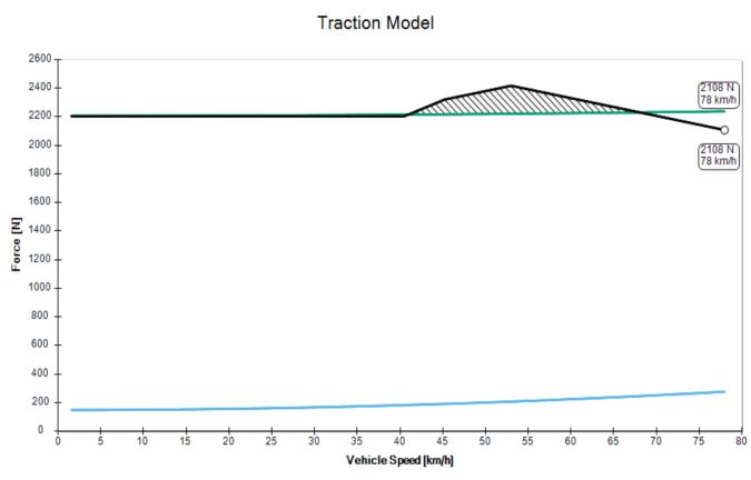
For this particular simulation, input parameters are weight, aero model,tire data,motor rpm and torque, gear reductionratioandfinaldriveratio.
Figure4:EngineTorqueandPowervsEngineSpeed

International Research Journal of Engineering and Technology (IRJET) e ISSN:2395 0056
Volume: 09 Issue: 05 | May 2022 www.irjet.net p ISSN:2395 0072
The torque transmitting capacity of the clutch packs used in the differential can be given in the following equation: ( ) ( )
In order to keep the torque difference constant, we have iterated the mentioned parameters on the right hand side oftheequation.
Theprimarystepwastoknowtheloadtransferandlateral acceleration values. For this, the vehicle was equipped withlockeddifferentialandwasdrivenonacourse,having hairpin, of minimum radius of 4.5m. This course was set with respect to the regulations provided by the competition official's .The vehicle was attached with accelerometer and was placed at the centre of gravity of thecar.
Logged acceleration data helped us find the mode acceleration value and deduce the corresponding maximumloadtransfervalueforthatmodeacceleration.
Weight transfer calculations:
The lateral load transfer is found from the following formula: Itdependsonvariousvehicleparameterssuchasheightof centre of gravity from the ground and front axle, track widthandloaddistribution.
Sinceweareawareoftheloadtransferexperiencedduring lateral acceleration and static load on each rear wheel; tractive force can be found by multiplying the friction coefficientwithwheel loadandlateralaccelerationatthat instant.
From longitudinal tractive force, tractive torque at each wheel wasfound. The ratio oftorque on rear wheelsgave us the torque biasing ratio at the instant of maximum lateralacceleration.
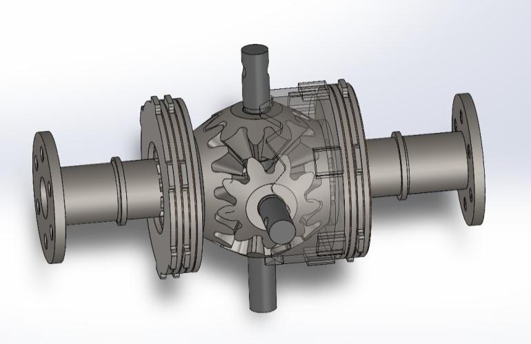


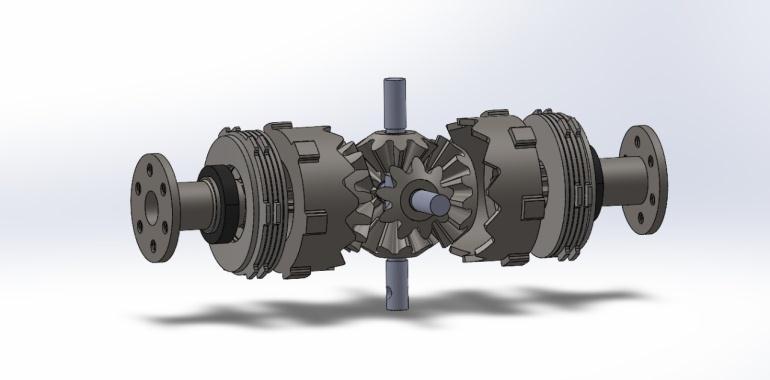
After accumulating the requisite parameters such as dimensions, final drive ratio, running torque and consideringpackagingandvariousotherconstraints,acad model was developed as shown which was then analysed onFEAsoftware's.
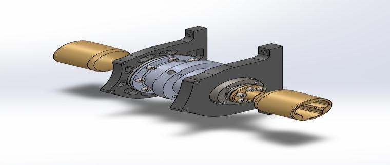
Figure 6: Assembly without Casing
Figure7:AssemblywithCasing
International Research Journal of Engineering and Technology (IRJET) e ISSN:2395 0056
Volume: 09 Issue: 05 | May 2022 www.irjet.net p ISSN:2395 0072
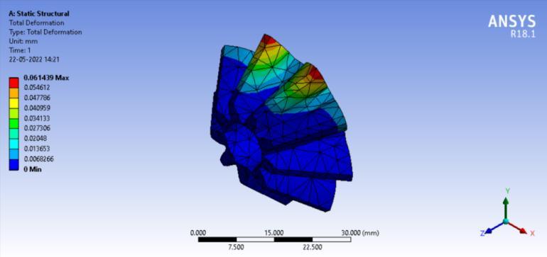
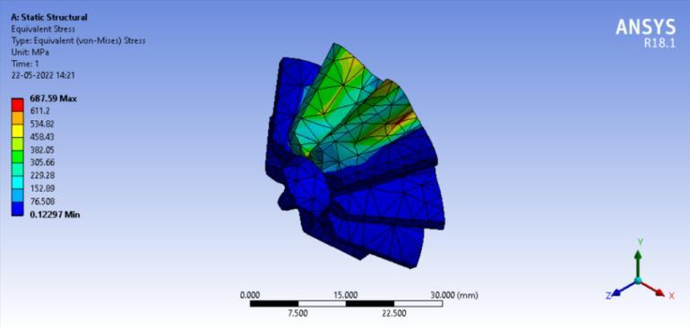
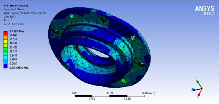
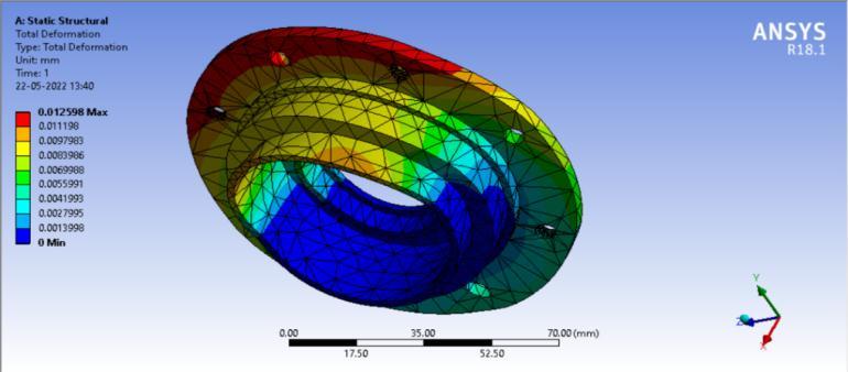
Solidworks2021wasusedtomodelallofthecadfiles,and Ansys Workbench 18.1 was used for analysis. The above results were obtained by simulating the load case with torque coming through the final drive on the differential. The gears are made of 18CrNiMo7 6, and the casing is made of aluminium 7075 T 6. The properties of 18CrNiMo7 6 gradesteel aresuperiortoC15 or 20MnCr5 grade steel in terms of yield strength, tensile strength, impactvalue,andpercentageofareareduction.Asaresult, the material can withstand a large amount of load with minimal bending stress, reducing wear and increasing tooth life, significantly increasing product life and efficiency.
The effectiveness of the limited slip differential must be tunedtofulfilvarioustypesofdrivingsituations,asshown inthepreviousdiscussion.
First, the unit's traction enhancements must provide appropriate traction performance to suit the extreme racing expectations in the most difficult circumstances. The shape of the bias ratio curve required to meet the
International Research Journal of Engineering and Technology (IRJET) e ISSN:2395 0056 Volume: 09 Issue: 05 | May 2022 www.irjet.net p ISSN:2395 0072
vehicle performance needs will then decide the type and number of clutch assemblies to be used. Many of these different combinations need to be evaluated depending upon various parameter including traction, vehicle setup etc.
The current paper reviews the working principles of differentials, design, benefits, analysis of limited slip differentials, with a focus on the ramp differential and clutch plates which is still the industry standard in professionalmotorsport.
Wewouldliketotakethisopportunitytoexpressourdeep sense of gratitude towards the people who have been instrumental in this successful completion of research on our topic Self locking clutch type differentials. We are deeplyindebtedto Prof. S. A. Dayane (AssistantProfessor, SoME,MITWPU,Pune)forhisvaluableinsightsandexpert guidanceinmakingusunderstandthe basicfundamentals involvedintheproject.
This Acknowledgement will remain incomplete without our sincere thanks to Prof. P. B. Joshi (Joint Managing Trustee, MAAER’S Group of Institutes), Prof. Dr. G. M. Kakandikar (the HoS of the School of Mechanical Engineering), Prof Dr. P. D. Khandekar (theDeanofFoE) for all the guidance, support and encouragement throughoutthework.
[1] William Milliken and Douglas Milliken, “Race Car VehicleDynamics,”1985
[2] Rouelle C., Kloppenborg S., “Differential behaviour” OptimumG lecturenotes.
[3] Ronald H. Haas and Richard C. Manwaring, “Development of a Limited Slip Differential”, SAE International by Purdue University, Tuesday, August 21, 2018.
[4] Marco Gadola and Daniel Chindamo, “The Mechanical Limited Slip Differential Revisited: High Performance and Racing Car Applications,” International Journal of Applied Engineering Research, ISSN 0973 4562 Volume 13, Number2(2018)pp.1478 1495.
[5] Pacejka, H.B.,” Tire and vehicle dynamics”, Society of AutomotiveEngineersInternational,(2012).


Mr. Pulkit Dubey is currently pursuing his Final Year B.Tech course in the School of Mechanical Engineering,Dr.VishwanathKarad MIT World PeaceUniversity,Pune, Maharashtra,India.

Mr. Vinit Dhamne is currently pursuing his Final Year B.Tech course in the School of Mechanical Engineering,Dr.VishwanathKarad MIT World PeaceUniversity,Pune, Maharashtra,India.
Prof. Shailendra A. Dayane is currently working as an Assistant Professor in MIT, Pune since the year 2000. He is a graduate from VNIT,Nagpur.

Mr. Shubham Kale is currently pursuing his Final Year B.Tech course in the School of Mechanical Engineering,Dr.VishwanathKarad MIT World PeaceUniversity,Pune, Maharashtra,India.
Mr. Chaitanya Deshmukh is currently pursuing his Final Year B.Tech course in the School of Mechanical Engineering, Dr. Vishwanath Karad MIT World Peace University, Pune, Maharashtra,India.