International Research Journal of Engineering and Technology (IRJET) e ISSN: 2395 0056

Volume: 09 Issue: 05 | May 2022 www.irjet.net p ISSN: 2395 0072
International Research Journal of Engineering and Technology (IRJET) e ISSN: 2395 0056
Volume: 09 Issue: 05 | May 2022 www.irjet.net p ISSN: 2395 0072
1 Assistant Professor, KKR & KSR Institute of Technology and Sciences 2,3,4,5,UG student, KKR & KSR Institute of Technology and Sciences ***
Abstract Mechatronics is a multidisciplinary field that refers to the set of skills needed in the current industry, advanced automated production and deals with robots, control systems, electronic systems. A programmable logic controller (PLC) is a type of small computer that can receive datathroughitsinputandsendinstructionsforitsoutputand requires input from auto capture data points or input areas such as switches or buttons. Staircling is an old and representative language of the system with a staircase drawing based on circuit drawings. It is widely used in developing systems or software for systematic thinking controls. In this project we are going to develop a mechatronicsapproachfordesigningtheprogrammablelogic controller with ladder programming to control the elevator.
Index terms: PLCs, Mechatronics, Ladder programming.
Mechatronics is a multi industry component focusingontheskillsetsrequiredinthecurrent,advanced automation manufacturing industry. Mechatronics works withrobots,controlsystems,andelectromechanicalsystems. The main components of Mechatronics are Modeling of VisualSystems,SensorsandActuators,SignalsandSystems, Computers and Sensitive Systems, Software and Data Recovery. Mechatronics is used in manufacturing, health care, spatial testing, and tools that make our lives easier everyday.
Alogicalcontrollerisatypeofsmallcomputerthat canreceivedataaccordingtoitsinputandsendoperating instructionsforitsresults.Industrialcomputersareusedto control various electro mechanical processes for use in production,plants,orotherautomotiveapplications.
Thesystematicmindcontrolreceivesinformation fromconnecteddevicesandsensors,processesthereceived data,andtriggerstherequiredoutputaccordingtoitspre setparameters.Basedoninputsandoutputs,PLCcaneasily monitorandrecordoperatingtimedatasuchasoperating temperature,machineproduction,alarmproductionwhen the machine fails, automatic start and stop processes and more. This means that PLCs are robust and flexible production control control solutions that are compatible withmostapplications.
Theoperatingsystemofanelevatororelevatorissimilarto apulleysystem.Awaterpumpsystemisused.Thispulley systemcanbedesignedwithabucket,awheelbarrow.The bucketisattachedtoaropethatpassesthroughtheentire wheel.
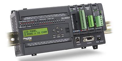
The A programmable logic controller (PLC) system is specially designed with a digital based microprocessor control system that uses systematic internal memory for instruction and internal storage for ordering and using functionssuchasthinking,scheduling,time,calculationand arithmetictocontrolequipment.andprocedures.
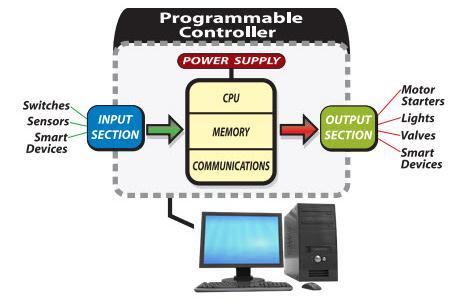
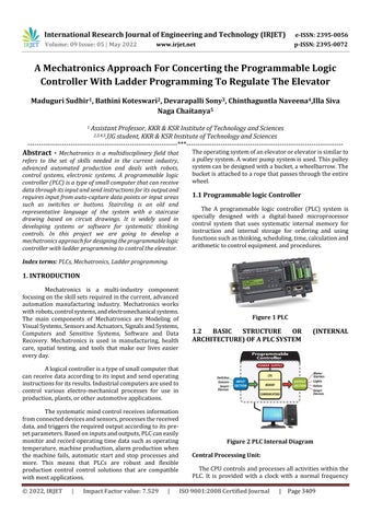
Figure 1 PLC
TheCPUcontrolsandprocessesallactivitieswithinthe PLC. It is provided with a clock with a normal frequency
International Research Journal of Engineering and Technology (IRJET) e ISSN: 2395 0056
Volume: 09 Issue: 05 | May 2022 www.irjet.net p ISSN: 2395 0072
between 1 to 8 MHz. This figure determines the PLC operating speed and provides time and synchronization acrossallsystemcomponents.Theinformationwithinthe PLC is handled by digital signals. The processor is a microprocessorthatperformsataskprogramspecifiedina ladderdrawingorsetofBooleanstatistics.TheCPUconsists ofthefollowingunits
This unit performs data manipulation and arithmetic and logical functions in flexible input data and determines the appropriate state of output variability. Arithmeticoperationsincludeaddition,subtractionetc.,and logicalfunctionsincludeAND,OR,NAND,X OR.
Memory termed registers located within the microprocessorandusedtostoreinformationinvolvedina programexecution.Theseprogramscontaincontrolactions to be executed by the microprocessor for the given input. ThereareseveralmemoryelementsinaPLCsystem.System Read onlyMemory(ROM)givespermanentstorageforthe operatingsystemandfixeddatawedbytheCPU.RAMforthe usertodevelopprogramandactsatemporarymemory.In addition,temporarybufferstoresfortheI/Ochannels.
Thecontrolunitisusedtocontroltheoperatingtime.The processoroperatesunderapermanentmonitoringoperating systemthatdirectsalloperationsfrominputandoutputto useroperatingsystems.Thecontrollercanperformonlyone task at a time. Therefore, it checks each input sequence, checks the step diagram program, gives each output, and then repeats the whole process. Therefore, time managementisrequiredinthePLCsystem.
Thesequenceofinstructionstobeexecuted,programsare stored in the memory unit. During entering and editing includingDebugging,theprogramisstoredinthetemporary storages called RAM (Random Access memory). Once the programiscompletelyfinished(free&fromerrors).Itmay be'burned'intoROMWhentheROMispluggedintothePLC, thedeviceisreadytobeplacedintoserviceintheindustrial environment.FornetworkprogrammedPLCs,thefinalPLCs program is downloaded into a special re programmable ROM(EPROM,PROM,andEEPROM)inthePLC.Memorymay beeithervolatiletypeorNon volatiletype.
Flexible memory or temporary memory or Applicationmemoryisausermemory,inwhichtheusercan loginandedittheprogram.Flexiblememorywillloseallits scheduledcontentiftheoperatingsystemisdischargedor
lost.Therefore,itisnecessarytoprovidebatterypoweratall times.
Fixed memory or permanent memory or system memory(used)systemmemorythatkeepstrackofstartup programs,viewingtables,etc.,Thisisusuallyplannedand providedbythemanufacturer.Thiscontrolstheoperationof PLC.Itdoesnotlose.itscontentatthetimeofexpiration.It doesnotrequireabattery.RROMmemoryprovidestheCPU tousealimitedamountofdataonly.
2.1.1
According to this project, the design of the cash laddersystemrequiredisprovidedbyaprogrammablelogic control(PLC),sodependingontheinputoutputisavailable.
Requiredinputsarekeyswitch,dooropeningand closing sensors, weight sensor, census sensor, pressure buttons,lightswitch,alarmswitch,obesitysensor.
2022, IRJET | Impact Factor value: 7.529 | ISO 9001:2008 Certified Journal | Page3410
International Research Journal of Engineering and Technology (IRJET) e ISSN: 2395 0056
PLCeffectsforUp&downengine,liftindicator,fan, light, up and down arrow, speaker, alarm and number indicator.
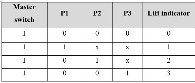
Toperformanyoperationwiththelift,themaster switch will be always in ON condition irrespective of the otherpushbuttons.
If we press the first push button, irrespective of otherpushbuttonstheliftwillmovetofirstfloor.
Ifwepressthesecondpushbutton,irrespectiveof otherpushbuttonstheliftwillmovetosecondfloor.
Ifwepressthethirdpushbutton,irrespectiveofotherpush buttonstheliftwillmovetothirdfloor.
The push buttons will work based onthe priority base first press first priority irrespective of other push buttons.
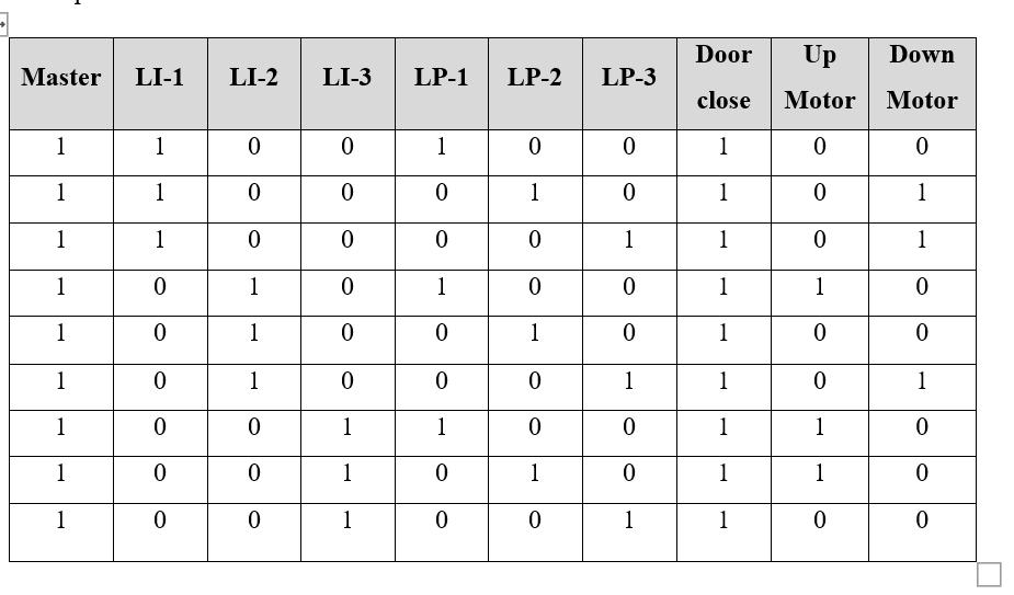
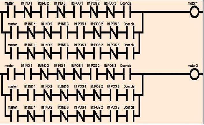
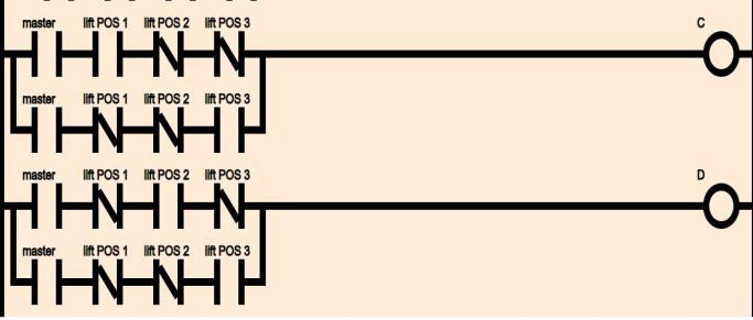
Wehavewrittentheladderprogrammingforthree floors,soforthethreefloorswehavetakentheparameters masterswitch,liftindicator 1,liftindicator 2,liftindicator 3, liftposition 1,liftposition 2,liftposition 3,doorclosetotell whentheUPmotorwillON/OFFandDownmotorON/OFF.
Toperformanyoperationwiththelift,themaster switchwillbealwaysinONconditionirrespectiveoftheup anddownmotors.
Basedonthebelowtruthtablewecansayatwhat conditiontheUPmotorwillturnONandturnOFFandwhat conditiontheDownmotorwillturnONandturnOFF.
TheUPmotorwillturninthefollowingconditions, theyare:
TheUPmotorwillturnONwhentheliftindicator 2, theliftposition 1anddoorcloseshouldbeinONstate.
TheUPmotorwillturnONwhentheliftindicator 3, theliftposition 1anddoorcloseshouldbeinONstate.
TheUPmotorwillturnONwhentheliftindicator 3, theliftposition 2anddoorcloseshouldbeinONstate.
ExcepttheseconditionstheUPmotorwillbeinOFF state.TheDownmotorwillturninthefollowingconditions, theyare:
TheDownmotorwillturnONwhentheliftindicator 1,theliftposition 2anddoorcloseshouldbeinONstate.
TheDownmotorwillturnONwhentheliftindicator 1,the lift position 3 and door close should be in ON state. The DownmotorwillturnONwhentheliftindicator 2,thelift position 3anddoorcloseshouldbeinONstate.Exceptthese conditionstheDownmotorwillbeinOFFstate.
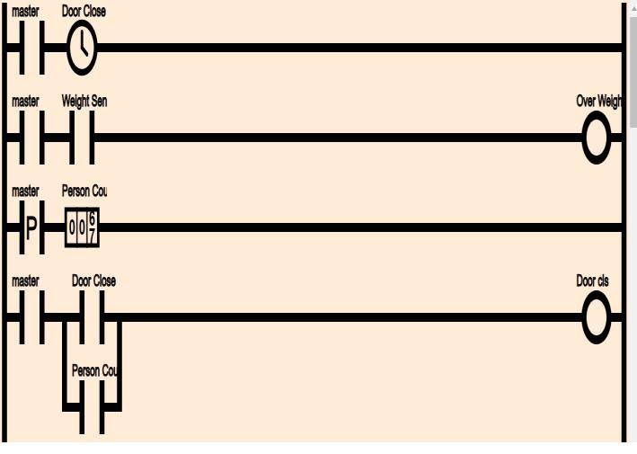
Based on the below truth table, to close the door automaticallywehavetakensomeparametersbasedonthat thedoorwillcloseautomaticallytheyare
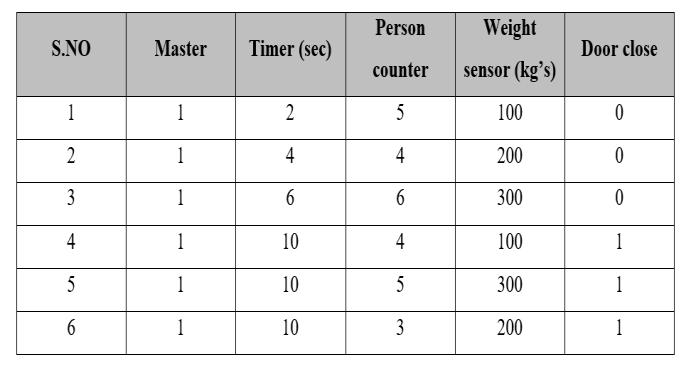
The parameters timer, person counter, weight sensoranddoorclose
Thedoorwill closeautomatically,whenthereare five members or four members in the lift and the lift will waitupto5secondsor10secondandtheweightittakesup to400kgsor300kgsor200kgs.
Volume: 09 Issue: 05 | May 2022 www.irjet.net p ISSN: 2395 0072 © 2022, IRJET | Impact Factor value: 7.529 | ISO 9001:2008 Certified Journal | Page3411
International Research Journal of Engineering and Technology (IRJET) e ISSN: 2395 0056
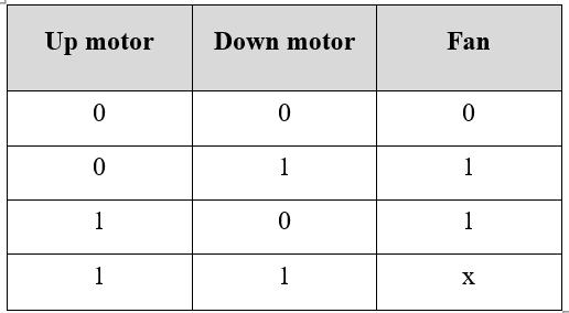
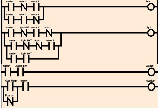
BasedonthemomentofUPmotorandDownmotor thefanwillbeturnedON.Fromthebelowtruthtable,wecan observethattheFanturnononlyintwoconditionstheyare:
WhentheupmotorisinOFFstateanddownmotorisinON statethefanwillbeturnedONandwhentheupmotorisin ON state and down motor is in OFF state the fan will be turnedON.WhenbothupmotoranddownmotorisONstate thenthefanstateiseitherinONorinOFFstate.
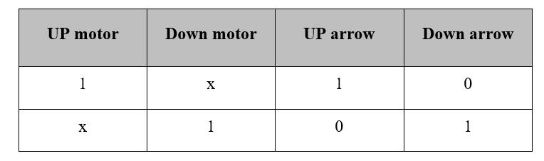
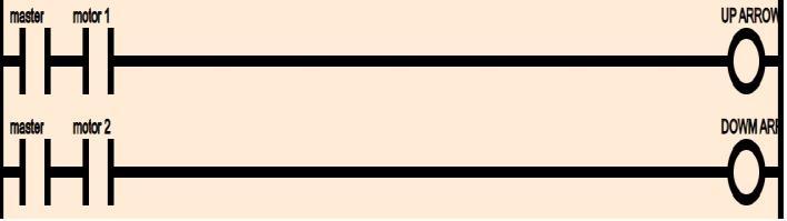
Based on the below truth table, the up and down arrowwillbeturnedbasedtheconditionstheyare:TheUP arrowwillbeturnedONwhentheupmotorisinONstate, irrespectiveofthedownmotorstate.TheDownarrowwill be turned ON when the down motor is in ON state, irrespectiveoftheupmotorstate.
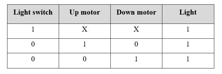
ThelightintheliftisturnedONonlybasedonthe conditionofupmotor,downmotorandstateoflightswitch thatiseitherinOFF/ONstate.
ThelightisturnedONonlyinthreeconditionsthey are:


IfthelightswitchisinONstatethenthelightinthe liftwillbeinONstate,irrespectiveoftheupmotoranddown motorconditions.IftheupmotorisinONstate,lightwillbe turned ON,where the light switchand down motorare in OFF state. If the down motor is in ON state, light will be turnedON,wherethelightsswitchandupmotorareinOFF state.
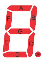

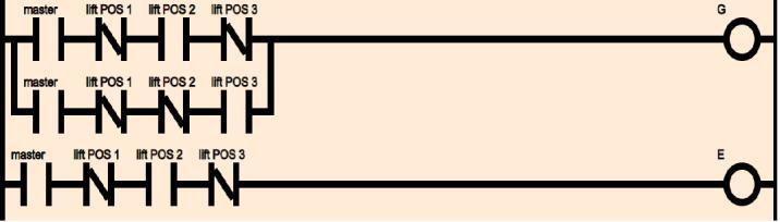
The above picture shows the seven segment display, whichisusedtodisplaythecurrentstatusoftheliftposition.
Theabovepictureindicatesthattheliftpositionwasin firstfloor,whereonly‘B’and‘C’statesareinONstateand remainingstatesareinOFFstate,soitindicatesthenumber ONE.
Theabovepictureindicatesthattheliftpositionwasin secondfloor,whereonly‘A’,‘B’,‘G’,‘E’and‘D’statesare in ONstateandremainingstatesareinOFFstate,soitindicates thenumberTWO.
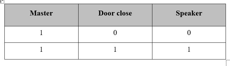
Basedonthebelowtruthtable,thespeakerwillbe turnedONinthefollowingconditionthatisWhenboththe master switch and door close are in ON state then the speakerwillturnedON.
Theabovepictureindicatesthattheliftpositionwasin thirdfloor,whereonly‘A’,‘B’,‘G’,‘C’and‘D’statesareinON stateandremainingstatesareinOFFstate,soitindicatesthe numberTHREE.
Volume: 09 Issue: 05 | May 2022 www.irjet.net p ISSN: 2395 0072 © 2022, IRJET | Impact Factor value: 7.529 | ISO 9001:2008 Certified Journal | Page3412
International Research Journal of Engineering and Technology (IRJET) e ISSN: 2395 0056
Volume: 09 Issue: 05 | May 2022 www.irjet.net p ISSN: 2395 0072
Therefore, this paper describes the design and developmentofPLCelevatedsupported.Theladderconcept is implemented using an online PLC template. It can be concluded
PLCscanbeusedtodesignacashmanagementsystem.

Traditionally used relay boards and IC boards can be replaced by PLC to make it easier and cheaper to control elevators.
ThedesiredcashpositioncanbepredictedusingaPLC basedcontrolsystem.
ByusingaPLCbasedoncashmanagementsystem,the size of the entire infrastructure can be reduced, including materialcosts,installationcostsandpersonnelcosts.
International Research Journal of Engineering and Technology (IRJET) e ISSN: 2395 0056
Intoday'sdevelopedworldelevatorsarebecoming increasingly important through the development of architectural technology. The design of the cash based controlsystemisveryimportantasitisveryimportanttodo allthework.Staircaselayoutispreferredasitiseasytoplan differentPLCs.Beforeembarkingonthisprojectithasbeena challengeforustodevelopaproperstepladderapproachas westartedinthePLCplanningfield.Graduallyweareableto design a ladder by adapting to different types of PLC systems. By splitting all the interfacing modules into separatesectionswealsosuccessfullycompleted.
[1] Xialoling Yang, Qunxiong Zhu, Hong Xu,, “Design and practice of an elevator control system based on PLC”, In proceedings of IEEE workshop on Power Electronics and IntelligentTransportationSystem,pp.94 992008.
[2] Dae Woongchung, Hyung Min Ryu, Young Min Lee, “Drive systems for high speed gearless elevators”, IEEE industryApplicationsMagazine,vol.7,pp52 56,2001
[3] Darshil, Sagar, Rajiv, Pangaokar, S.A. Sharma, “DevelopmentofaPLCBasedElevatorSystemwithColour Sensing Capabilities for Material Handling in Industrial Plant”,InproceedingsofIEEEJointInternationalconference onPowerSystemTechnology,pp1 7,2008
[4]Eunsonjung,HyunjaeYoo,Seung kiSul,Hong soonChoi and Yun Young Choi, “ A Nine Phase choi and Yun Young Choi, an Ultrahigh speed Elevator”, IEEE Transactions on IndustryApplication,vol.48,pp987 995.
[5]PengWang,“AControlSystemDesignforHandElevator Based on PLC”, In proceedings of IEEE Conference Publications,vol.1,pp77 74,2012

Mr. Maduguri Sudhir, (M.Tech. with specialization in Digital Electrinics and Communication System ), He have special interest on Digital Image Processing and Ladder Programming. He has 12 years of experience in academics. Presently he is workingasAssistantProfessorinKITSEngineeringCollege, Guntur,AP.

Ms. Devarapalli Sony is a UG Student of ElectronicsandCommunicationEngineering, JNTUK,Kakinada,AP.Sheisveryinterestedin automationsystems


Ms Chinthaguntla Naveena isaUGStudentof Electronics and Communication Engineering, JNTUK,Kakinada,AP.Sheisveryinterestedin AIsystems
Ms. Illa Siva Naga Chaitanya isaUGStudent of Electronics and Communication Engineering,JNTUK,Kakinada,AP.Sheisvery interestedinautomationsystems. systems.
Volume: 09 Issue: 05 | May 2022 www.irjet.net p ISSN: 2395 0072 © 2022, IRJET | Impact Factor value: 7.529 | ISO 9001:2008 Certified Journal | Page3414
Ms Bathini Koteswari is a UG Student of Electronicsand CommunicationEngineering, JNTUK,Kakinada,AP.Sheisveryinterestedin Micro controllers and Aurdino coding