International Research Journal of Engineering and Technology (IRJET)

Volume: 09 Issue: 04 | Apr 2022 www.irjet.net
e ISSN: 2395 0056
p ISSN: 2395 0072
International Research Journal of Engineering and Technology (IRJET)
Volume: 09 Issue: 04 | Apr 2022 www.irjet.net
e ISSN: 2395 0056
p ISSN: 2395 0072
1M.Tech, Civil Engineering, Suyash Institute of Information Technology, Gorakhpur, Uttar Pradesh
2Assistant Professor, Civil Engineering, Suyash Institute of Information Technology, Gorakhpur, Uttar Pradesh
***
Abstract - Inthis researchstudy, we studiedthe responseof the different composite columns inthe multistoreybuildingby using dynamicanalysis. Inthis paper, we createdthreemodels which have different composite columns. In the model 01, we provided the general RCC column; in the model 02, we provided the column in which the tube is provided; in the model 03, we provided the I section steel with the reinforcement, where the purpose of the using the reinforcement in the model 03 is that proper joint can be created between the beam and column. These three models will be analyzed with the help of the ETABS software by using the Indian standard Seismic code 1893 part 1:2016. The method used for the analysis of these models is the Time History Method and data of the time history was taken from “Andaman” whose magnitude was 7.8. After the analysis of these three models, we will compare the result based on the seismic parameter such as Storey acceleration, Mode shape, Column force, StoreyOverturning moment, Base reactionand then we will compare the stability of these three models with the help of this seismic parameter.
Key Words: Dynamicanalysis,timehistoryanalysis,CFST column,CompositeSection,ETABS.
TheCFSTcolumnisastructuralelementmadeofsteeltubes withaconcretecore.TheoutertubeoftheCFSTcolumnnot onlylimitstheconcretecorebutalsopreventsthesteeltube from collapsing inward [1]. Because of its excellent load carryingcapacity,cheapcost,andlabourefficiency,thistype of composite element has recently been popular in many load bearingstructures.Existingdesignstandardssuchas Japanese standard [6], American code AISC 360 16 [7], Eurocode 4 [8], allow for maximum yield stresses of 440 MPa,525MPa,460MPa,and690MPa,respectively,forthe steelgradeusedinCFSTcolumns.Steelwithhighyieldstress hasamuchhigheryieldstrainthanconcrete,whichisoneof the main reasons for these limitations. As a result, the concretecoreusuallycrushesbeforethehigh tensilesteel yields [10]. The construction of multistory RCCs is now expandingdaybyday,andasthestructure'sheightrises,so doesthenumericalvalueoflateralpressuressuchasseismic and wind forces. To withstand the lateral force on a multistory building, we must construct a more robust structurethatcanwithstandthelateralforceeasily.
value:
We know that steel is needed to support the structure's tensileforceandthatthenatureofthelateralloadistensile, thereforewegiveasteeltubeinmodel02andanI section with reinforcement in model 03 that can withstand that lateralload.
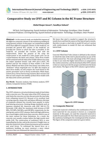
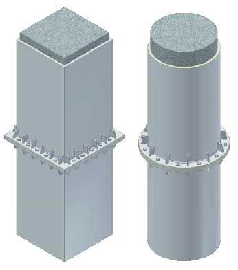
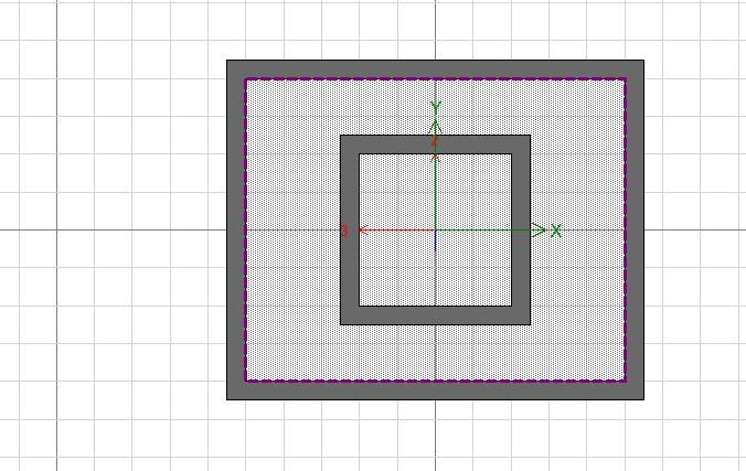
ConcreteFilledSteelTubecolumnisdefinedasthecolumn inwhichthetubeofthesteelisplacedandhasnouseofthe reinforcementbar.ThemainadvantageoftheCFSTcolumn isthatitcanresistthehigherlateralforceascomparedto thereinforcementbar,andthedrawbackoftheCFSTcolumn isthatwecannotprovidetheproperjointbetweenthebeam andcolumn.ThefigureoftheCFSTcolumnisgivenbelow:
Compositematerialisdefinedasthecombinationoftwoor more materials for one purpose is known as a composite material.Inthispaper,weusedthecompositematerial in model 02andmodel 03.HereSteelandconcreteareusedin themultistorybuildingfortheresistingloadofthestructure. Thefigureofthecompositematerialisgivenbelow:
International Research Journal of Engineering and Technology (IRJET)
Volume: 09 Issue: 04 | Apr 2022 www.irjet.net
e ISSN: 2395 0056
p ISSN: 2395 0072
IS875(Part1)CodeofPracticeforDesignLoads(Otherthan Earthquake) For Buildings and Structures.Part 1: Dead Loads Unit Weights of Building Materials and Stored Materials.InthisIndianstandardcode,thevalueoftheunit weightofthematerialsisgiven.
Inthemethodology,westudiedthemethodwhichisusedfor theanalysisofthesemodels,IndianStandardCode,Software, load combination, load case, building parameter, seismic parameter,etc.
Inthisresearchpaper,weusedthedynamicanalysisofthe CFSTcolumninthemultistoriedbuildingbyusingtheTime History Analysis. The dynamic analysis is used when the variationofthelateralforceconcerningthetimeishigh,or the study of the structure in the moving condition. In the StaticMethod,westudythestructurewhenthatstructureis in the rest or equilibrium condition, or variation of the lateralforceconcerningthetimeislow.
Thesoftwareusedforcreatingandanalysisofthesemodels is ETABS software, which was developed by the CSI Company. ETABS software is used for the analysis and designingofthestructurewiththevarioustypeofload.In thissoftware,theStandardcodeisalmostuploadedwhichis used for analyzing the structure by using particular that standardcode.
Inthisresearchpaper,weusedmainlyfourIndianStandard codessuchasIS 456:2000,IS875 part 1,IS875 part 2,and IndianStandard1893part 1:2016.
IS456 2000PlainandReinforcedConcrete CodeofPractice isanIndianStandardcodeofpracticeforgeneralstructural use of plain and reinforced concrete. ... It gives extensive information on the various aspects of concrete. Load Combination. In this Indian standard code, the minimum reinforcementareaofthecolumn,beamandslabisgiven; basedonwhichwechecktheminimumreinforcementarea.
Thisstandard(Part2)coversimposedloads(liveloads)to beassumedinthedesignofbuildings.Theimposedloads, specified herein, are minimum loads that should be taken intoconsiderationforthestructuralsafetyofbuildings.This Indian standard code gives the value of the live load accordingtothetypeofthestructure.
2.3.4. IS Code 1893: Part 1: 2016
This Indian standard code is used for the Earthquake ResistantDesignoftheStructure,inthiscode,theseismic parameter is given such as the seismic zone, importance factor,etc;whenweanalyzedstaticordynamicanalysisof thestructure.
Inthesethreemodels,wetooksomeloadcasessuchasthe deadloadofthestructure,liveloadontheslaborroof,wall load,andseismicforce.
Inthisparameter,wewillstudythesizeofthebeam,column, thickness of the slab, plan area of the building, the total height of the structure, etc. The table of the building parameterisgivenbelow:
© 2022, IRJET | Impact Factor value: 7.529 | ISO 9001:2008 Certified
International Research Journal of Engineering and Technology (IRJET)
Volume: 09 Issue: 04 | Apr 2022 www.irjet.net
Thematerialusedintheanalysisofthesethreemodelssuch asconcrete,reinforcement,etcisgivenbelowintheformof thetable:
S.No Material Name Grade
1 Concrete M40forbeam& Column
2 Concrete M30forSlab
3 MildSteel (Fe250) Isection & TubeSection
Theloadwhichappliesonthestructuresuchasdeadloador self weights live load on the slab or roof, live load on the beamisgivenbelowintheformofthetable:
S.No Load parameter Value
1 Deadload 6.9KN/m
2 Liveload 2.5KN/m
3 Liveload 4KN/m2
AccordingtotheIndianStandardCode,wehavetakenthe valueoftheseismicparameterbasedonthelocationofthe structure,typeofframessuchasOMRForSMRF,etcisgiven below:
Impact Factor value: 7.529
e ISSN: 2395 0056
p ISSN: 2395 0072
1. Importance Factor(I) 1.2 2. Response ReductionFactor (R)
3 3. ZoneFactor(z) 0.24 4. TypeoftheSoil 2nd 5. Eccentricratio 0.05 6. magnitude 7.8
7. Timehistorydata Andaman, 10/08/2009 19:55:35UTC
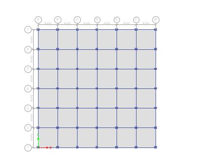
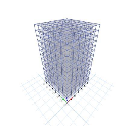
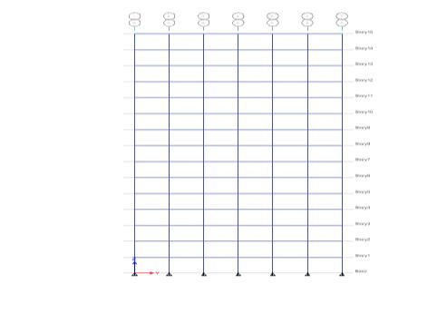
Inthemodel 01,weprovidedthenormalRCCcolumn,the detailsfigureofthemodel 01isgivenbelow:
9001:2008
International
Volume: 09 Issue: 04
Journal of Engineering and Technology (IRJET)
Apr
www.irjet.net
e ISSN: 2395 0056
p ISSN: 2395 0072
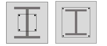
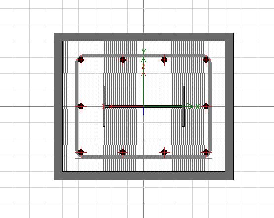
In model 03, we provided the I section steel with reinforcement in the column. The plan, elevation and 3D view of the model 03 are the same as model 01, but the cross sectionofthecolumninthemodel 03isdifferentfrom themodel 01.Thefigureofthecross sectionofthecolumn ofthemodel 03isgivenbelow:
Inmodel 02,weprovidedtheCFSTcolumnmeansproviding thetubeofthesteelinthecolumn.Theplan,elevationand 3Dviewofthemodel 02arethesameasmodel 01,butthe cross sectionofthecolumninthemodel 02isdifferentfrom themodel 01.Thefigureofthecross sectionofthecolumn ofthemodel 02isgivenbelow:
In the result and analysis, we will study the result which comes out after the analysis of three models, and then compare all results of each model will be compared with othermodelsintheformofagraph.Afteranalyzingalldata concerning each other, we will see which model is more stable and durable as compared to other models. The parametertakenfortheanalysisofthemodelsis:
i. DesignReaction
StoreyAcceleration
ModeShape iv. ColumnForce
StoreyOverturningMoment
Design reaction is defined as the vertical force which is developedatthebaseofthestructure,thedesignreaction resistsalltheforcesorloadwhichisactingonthesemodels. ThevalueofthedesignreactionistakenduetoloadcaseEX whichisaseismicforceintheX direction.Thegraphofthe designreactionisgivenbelowofthesethreemodelsalong theFZ(verticalloadalongZ direction):
International
Journal of Engineering and Technology (IRJET)
Volume: 09 Issue: 04 | Apr 2022 www.irjet.net
e ISSN: 2395 0056
p ISSN: 2395 0072
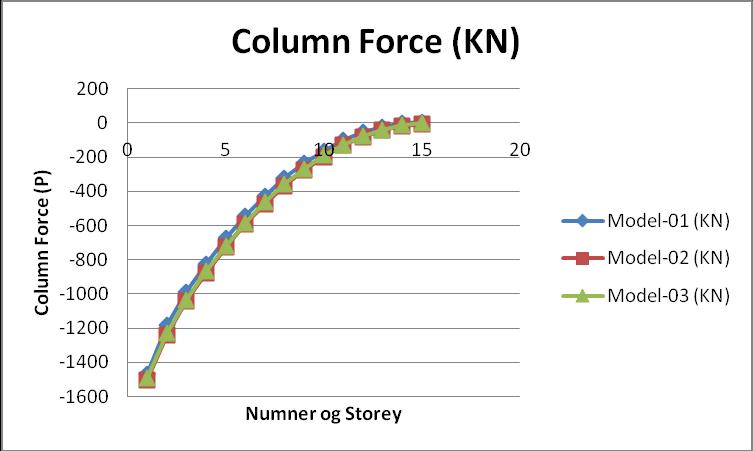
Column force is defined as the vertical force in the compressivenaturewhichcomefromtheabovestructureto thecolumn.Designthecolumntoresistthatparticularload ofthecolumnforce. Thevalueofthecolumnforcedueto loadcaseEX,thegraphofcolumnforceisgivenbelow:
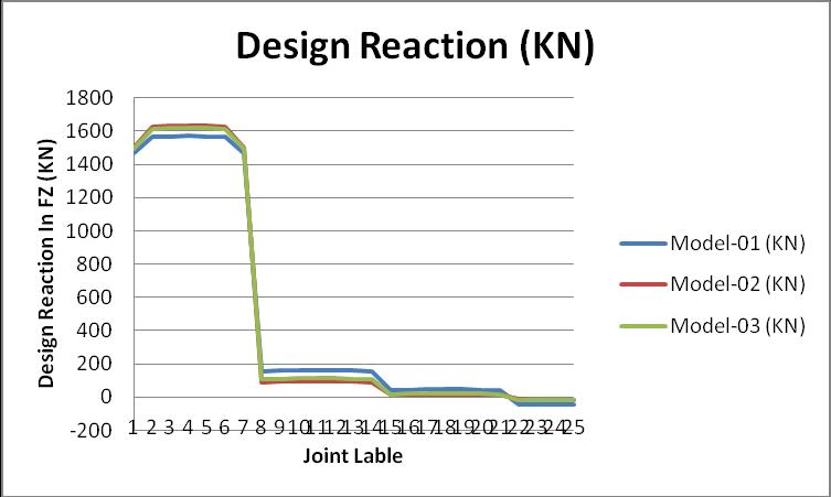
Fromtheabovegraph,wecananalyzethemaximumvalueof thedesignreactionatthejointlabel06whichispresentat thebaseofthemodel.
Storey acceleration is defined as the acceleration of each storeyofthestructureduetoapplyingthelateralloadonthe structure.Theeffectofthestoreyaccelerationishighinthe case of the lateral load and minimum in the case of the verticalload. Thevalueofthestoreyaccelerationistaken alongtheloadcaseEXwhichisappliedinthemodel,anda graphofthestoreyaccelerationalongUXisgivenbelow:
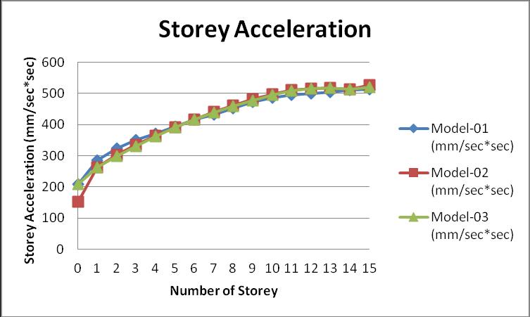
From the above graph of the storey acceleration, we can analyzethemaximumresponseofthestoreyaccelerationin model 02.
Fromtheabovegraphofthecolumnforcesofthemodels, the maximum value of the column force in the mode 02, wherethetubeofthesteelprovidedinthecolumn.
Storeyoverturningmomentisdefinedasthemomentwhich acts on every top layer of the storey of the structure. The effect of the overturning moment is maximum due to applyingthelateralloadonthestructureascomparedtothe vertical load on the structure. The value of the maximum overturningmomentisproducedatthebaseofthestructure. Thegraphoftheoverturningmomentisgivenbelow:
International
Volume: 09 Issue: 04
Journal of Engineering and Technology (IRJET)
Apr
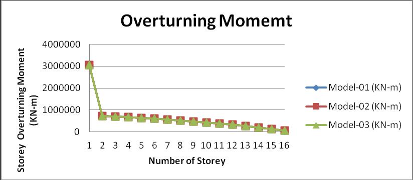
Fromtheabovegraphofthestoreyoverturningmoment,we can analyze that from storey 01 to storey 02 maximum changeoccurs.
i. ThevalueofthestoreyaccelerationoftheModel 02 inUXismaximumascomparedtotheothermodels, so we can say that model 02 is more flexible as comparedtomodel 1andmodel 3,becauseofthe effectofthelateralforceishighinthemodel 2.
ii. The value of the axial force in the column due to seismic forces in X direction in the Model 01 is minimumascomparedtothemodel 02andmodel 03. The value of the torsion and moment at the storey 01iszerosoitsmeansthatwedonotneed theextrareinforcementinthemodelsatthestorey 01.Weonlyneedtodesignthecolumnaccordingto theeffectoftheloadontheZ direction.
iii. Aftercomparingtheresultofthemodeshapeofthe threemodels,thenwefindthatthemodeshapeof model 01 at mode 01 is developed at 2.058 seconds, which is maximum as compared to the model 02andmodel 03.
iv. Concerning the above graph of the storey overturning moment, the summation of the total overturning moment in model 02 is maximum whichisequalto9750343KN m. Thevalueofthe storey overturning moment of the model 01 and model 03is0.000102%and0.00002051%lessas comparedtothemodel 02.
v. Fromtheabovetableofthedesignreaction,wecan seethatvalueofthedesignreactionofthemodel 01 ismaximumascomparedtomodel 02andmodel 03,sothecostoftheconstructingthefoundationto resist the design reactionis moreascompared to othermodels,butthemodel 02havealowvalueof the design reaction so it is more economical as comparedtoothermodels.
e ISSN: 2395 0056
p ISSN: 2395 0072
[1]P. Fajfar, A nonlinear analysis method for performance based seismic design, Earthquake Spect. 16 (3) (August 2000)573 592.
[2]Ketan Patela, Sonal Thakkarb* ANALYSIS OF CFT, RCC ANDSTEELBUILDINGSUBJECTEDTOLATERALLOADING, ScienceDirect,2012,51(2013)259 265
[3]Konstantinos Daniel Tsavdaridis, Seismic Analysis of Steel Concrete Composite Buildings: Numerical Modeling.2014, ScienceDirect, DOI 10.1007/978 3 642 36197 5_125 1
[4]SamehA.El Betar,SeismicperformanceofexistingR.C. framedBuildings.2015,Elsevier
[5]Pramodini Naik1, Satish Annigeri2, Performance Evaluation of ( storey RC building located in North Goa. ScienceDirect.2016,ProcediaEngineering173(2017)1841 1846
[6]IS:1893 2016,Criteriaforearthquakeresistantdesignof structures,BureauofIndianStandard,NewDelhi.
[7]IS 456 2000, Plain and Reinforced Concrete Code of Practice,BureauofIndianStandard,NewDelhi.
[8]IS800 2007,Codeofpracticeforgeneralconstructionin steel,BureauofIndianStandard,NewDelhi.
[9]AS/NZS2327,CompositeSteel Concreteconstructionfor buildings,Australia/StandardNewZealandStandard,2017.
[10] C. S. Kim, H. G. Park, K. S. Chung, I. R. Choi, Eccentric axialloadcapacityofhighstrengthsteel concretecomposite columnsofvarioussectionalshapes,J.Struct.Eng.140(4) (2014),04013091,.
[11]F.Aslani,B.Uy,Z.Tao,F.Mashiri,Predictingtheaxial loadcapacityofhigh strengthconcretefilledsteel tubular columns,SteelCompos.Struct.19(4)(2015)967 993.
[12]W. M.Gho,D.Liu,Flexuralbehaviourofhigh strength rectangular concrete filledsteel hollowsections, J.Constr. SteelRes.60(11)(2004)1681 1696.
[13] D.M. Lue, J. L. Liu, T. Yen, Experimental study on rectangular CFT columns with highstrength concrete, J. Constr.SteelRes.63(1)(2007)37 44.
[14]D.Liu,Behaviourofhighstrengthrectangularconcrete filledsteelhollowsectioncolumnsundereccentricloading, Thin WalledStruct.42(12)(2004)1631 1644.
[15] D. Liu, Tests on high strength rectangular concrete filledsteelhollowsectionstubcolumns,J.Constr.SteelRes. 61(7)(2005)902 911.
[16]L. H.Han,G. H.Yao,X. L.Zhao,Testsandcalculations for hollow structural steel (HSS) stub columns filled with self consolidatingconcrete(SCC),J.Constr.SteelRes.61(9) (2005)1241 1269.
[17]J.M.Portolés,E.Serra,M.L.Romero,Influenceofultra high strength infill in slender concrete filled steel tubular columns,J.Constr.SteelRes.86(2013)107 114.
[18]Z.Tao,L. H.Han,Z. B.Wang,Experimentalbehaviourof stiffenedconcrete filledthin walledhollowsteelstructural (HSS)stubcolumns,J.Constr.SteelRes.61(7)(2005)962 983.