International Research Journal of Engineering and Technology (IRJET)
e-ISSN: 2395-0056
Volume: 09 Issue: 02 | Feb 2022
p-ISSN: 2395-0072
www.irjet.net
CFX ANALYSIS OF AN IMPELLER BLADE DESIGN OF CENTRIFUGAL COMPRESSOR Ashutosh Kale1, Karan Varma2, Mayur Jogalpure3, Soumitra Shenolikar4 1-4P.E.S.
Modern College of Engineering, Mechanical Department, Pune, Maharashtra, India ------------------------------------------------------------------------***----------------------------------------------------------------------ABSTRACT– Turbochargers are devices that increase the output power of an internal combustion engine by forcing extra compressed air into the combustion chamber. An accurate and sustainable design of the turbocharger will improve the efficiency of our combustion engine. The most important part of the centrifugal compressor used to compress air is the impeller. Radial impellers have wide range of applications in turbochargers. The aim of this project is to design an impeller blade with the optimum back swept angle so that it can work efficiently. The study is to design and optimize an impeller blade using CFX analysis in Ansys software. The back swept angle will be changed and iterations will be taken until an optimum angle is found. The output data obtained from the analysis will be analyzed and parameters such as pressure ratio, Mach number and flow rate will be considered. Thus, an efficient blade design will help in improving the air flow distribution in the impeller and will in turn increase the overall efficiency of the turbocharger.
efficient and accurate design of a turbocharger is crucial to increase the output power of an engine. Turbochargers have become an essential component in modern automobiles as the need for faster and more efficient vehicles has increased. In the modern age more and more gasoline engines have started installing turbochargers.
KEYWORDS – Impeller Blade, Turbocharger, CFX Analysis, Back-Swept Angle, Centrifugal Compressor, Mach Number
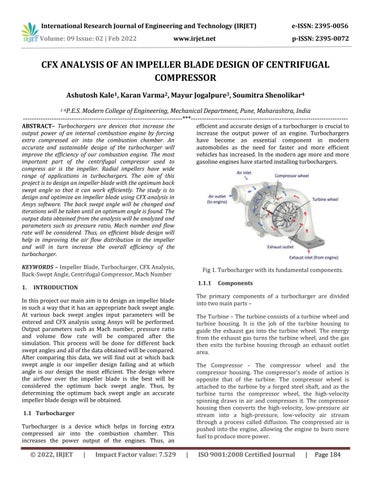
Fig 1. Turbocharger with its fundamental components.
1.
1.1.1
INTRODUCTION
The primary components of a turbocharger are divided into two main parts –
In this project our main aim is to design an impeller blade in such a way that it has an appropriate back swept angle. At various back swept angles input parameters will be entered and CFX analysis using Ansys will be performed. Output parameters such as Mach number, pressure ratio and volume flow rate will be compared after the simulation. This process will be done for different back swept angles and all of the data obtained will be compared. After comparing this data, we will find out at which back swept angle is our impeller design failing and at which angle is our design the most efficient. The design where the airflow over the impeller blade is the best will be considered the optimum back swept angle. Thus, by determining the optimum back swept angle an accurate impeller blade design will be obtained.
The Turbine – The turbine consists of a turbine wheel and turbine housing. It is the job of the turbine housing to guide the exhaust gas into the turbine wheel. The energy from the exhaust gas turns the turbine wheel, and the gas then exits the turbine housing through an exhaust outlet area. The Compressor – The compressor wheel and the compressor housing. The compressor’s mode of action is opposite that of the turbine. The compressor wheel is attached to the turbine by a forged steel shaft, and as the turbine turns the compressor wheel, the high-velocity spinning draws in air and compresses it. The compressor housing then converts the high-velocity, low-pressure air stream into a high-pressure, low-velocity air stream through a process called diffusion. The compressed air is pushed into the engine, allowing the engine to burn more fuel to produce more power.
1.1 Turbocharger Turbocharger is a device which helps in forcing extra compressed air into the combustion chamber. This increases the power output of the engines. Thus, an
© 2022, IRJET
|
Impact Factor value: 7.529
Components
|
ISO 9001:2008 Certified Journal
|
Page 184