International Research Journal of Engineering and Technology (IRJET)

e-ISSN:2395-0056
Volume: 09 Issue: 11 | Nov 2022 www.irjet.net p-ISSN:2395-0072
ENHANCEMENT OF MOLD EFFICIENCY USING CONFORMAL COOLING
1Mtech Scholar, Dept of Mechanical Engineering, Shri Govindram Seksaria Institute of Technology and Science, Indore 2 professor, Dept of Mechanical Engineering, Shri Govindram Seksaria Institute of Technology and Science, Indore
Abstract- Cooling time is typically the most important factor in injection molding cycles. Shorter cooling periods can benefit manufacturing. To reduce cooling time, proper setup is essential. Conventional molding techniques impede the design of the cooling system. The distance between cooling channels and curved cavities is adjustable. Local heat accumulates, lowering output quality. Non-traditional processes such as laser sintering and 3D printing can bring cooling channels closer to the cavity surface. To predict the injection molding process and product deformation, researchers are using a real 3-D simulator. This research compared traditional and conformal cooling. Flow patterns in cooling channels, according to the study, can improve cooling performance. Conformal cooling reduces cycle times while improving injectionmoldingproductquality.
Key words: conformal cooling, injection moulding, mould Design,Conventionalmolding,Conformalcooling
1. Introduction
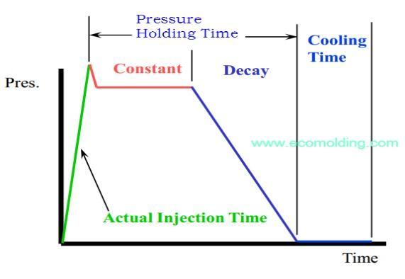
With the rapid development of modern industry, people's dailyneedsarebecomingmoreandmorediversified.Plastics have gradually replaced steel and wood in many fields and become the 21stOneof the mostimportant materialsofthe century. There are many molding methods for plastic products,suchasblowmolding,injectionmolding,extrusion molding, etc. Among them, the application of injection or stampingisthemostpopular.Itiscomposedofotherstages, inwhichthecoolingtimeaccountsforabout50%-80%ofthe mold cycle. The injection mold posture refers to the key factorthataffectsthequalityofplasticpartsandproduction failure rate. It not only directly affects the length of the molding cycle, but also determines the degree of deformation, mechanical properties, and dimensional accuracy of the molded plastic parts. The part problem is caused by the improper design of the mold cooling system. Therefore, the design and optimization of the mold cooling system is crucial for plastic injection molding. Since the 1960s, the design of cooling system has attracted the attentionofresearchers,andaseriesofresearchresultshave been obtained. However, in the actual production process,
duetotheinfluenceofvariousfactors,thetraditionalcooling technologycannotmeettheneedsofthestandard.
Companies that use injection molding look for ways to cut costswithoutcompromisingquality.Manufacturingcostsare impacted by the injection molding cycle time. Due to "cooling," injection molding is cumbersome. Increasing cooling speed could result in financial savings. Temperature alone does not determine the length of time it takes to cool. Think about the type of coolant, temperature, and flow rate. Multiple characteristics, such as the type of cooling system, may be difficult for conventional molding to accommodate. Constructing conformal cooling channels may be done via laser sintering and 3D printing. Dalgarno and Stewart used indirect selective laser sintering to produce a conformal cooling channel. 50% less time was spent cooling [1]. 3-D printing was invented by Sachs and his MIT colleagues [2]. According to study, conformal cooling molds maintain a steady temperature better than other types. Conformal cooling channels adhere to standards for cooling channel diameter, separation between channels, and distance from channel to cavity. With the aim of improving the most effective design, many investigations have resulted in many cooling channel architectural designs. This study demonstrated how conformal cooling influences tool and product temperatures and deformations using a model and simulations.
Reducing production costs and enhancing product performance are themes in fusion shaping. It takes a lot of timeandmoneytobuildaninfusion.It takesa whileto chill an infusion. Increasing your emergency money means reducingthecoolingtime.Thinkabouttheprintingmedium, coolant,coolanttemperature,etc.whendevelopingacooling time framework. Setting up the cooling infrastructure for traditional printing is difficult. Using a three-dimensional laser imprint, cooling channels can be discovered. Sintering is used by Dalgarno Stewart to put the cooling channels for the laser together. Cooling times were halved in both scenarios [1]. An further MIT tactic is three-dimensional printing [2]. When it came to controlling form temperature, conformal cooling outperformed other strategies. There is a rule that separates good approaches from pit to channel
International Research Journal of Engineering and Technology (IRJET) e-ISSN:2395-0056
Volume: 09 Issue: 11 | Nov 2022 www.irjet.net p-ISSN:2395-0072
cooling channel measurements [3]. Numerous studies determine an improved cooling channel format [4–7]. The temperature distortion and product instrumentation on conformal cooling were demonstrated in this work using a straightforwardmodelandnumericalrecreations.
1.1. Time Control
Ifyouhaveajob,officetime.Thisaffectstheprocess'slength. Door-to-entryway, infusion, and chilling times are standard. Itdeterminesprocessduration.Timecontrolcanhelpdecide amotor'scostandproductivity.
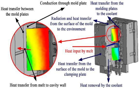
1.3. Pressure Control
The clasp structure and the infusion unit itself must be pressed to fill the contour when using the infusion unit. Weights for infusion units are initialized, collected, and returned.Allofthiswasobtainedbythescrew.Waterisused to move the form of the oil siphon's clasping mechanism. Compaction occurswhen theholdingconstraint iscritical in ordertocompensateforchamberfluid.
Figure 1: Cycletimeininjectionmoulding
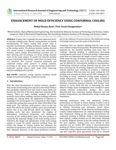
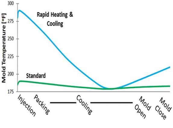
1.2. Temperature Control
To achieve the desired properties, the temperature must be adjustedduringhardening.Fluidpolymers,decorations, and clips are used to control the temperature of the structure (Fig. 1). Compress the plastic to frame the item. Pumping wateroroilaroundtheformcoolsit.Apartcanbeevacuated after it has cooled. Approaching materials compensate for 95% of form shrinkage; the remaining shrinkage must be replicated.[1].
Figure 3: Pressurehistoryduringinjectionmoulding
1.4. Thermal PROPRIETIES
Thetemperatureofthematerialmustbeabletoregulatethe heartbeat. Despite their widespread use, all plastics overheated. Plastics can be damaged by high temperatures. Tounderstandandpredictthis behavior, evaluatethewarm standard.Formcoolingmustbecontrolled.chinestoquickly chillitforthefollowingreasons:Thicknessofdispersionand plasticization Plastic diamonds that are not transparent are warmer than those that are. Plastics have a much higher warm extension coefficient than metals. Send a warning while remaining safe. Consider the remittance of depreciation.
Figure 2: Temperaturehistoryduringinjectionmoulding
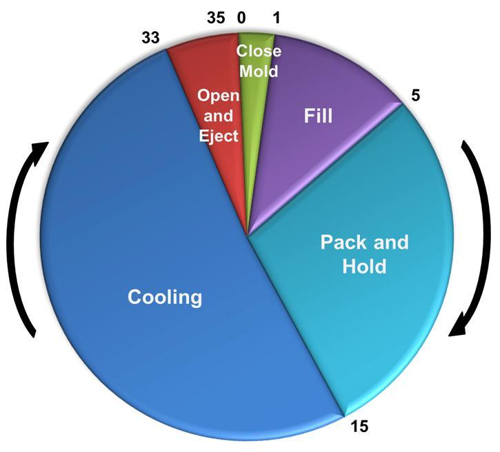
Figure 4: Thermalduringinjectionmoulding
International Research Journal of Engineering and Technology (IRJET) e-ISSN:2395-0056
Volume: 09 Issue: 11 | Nov 2022 www.irjet.net p-ISSN:2395-0072
2. Literature Review
2.1. Xu Chunlong et al.
Theinfluenceofcoolingsystemoninjectionmolding. Taking the design of the cooling system for pushing paper test piecesasanexample,theyanalyzedtheinfluenceofprocess parameters such as melt temperature and shape of plastic parts on cooling time during the cooling process. By determining the position of the Xiangdu loop and adjusting the process parameters in the cooling process, the cooling timeisoptimized.
2.2. Modelling Of Casting Patterns
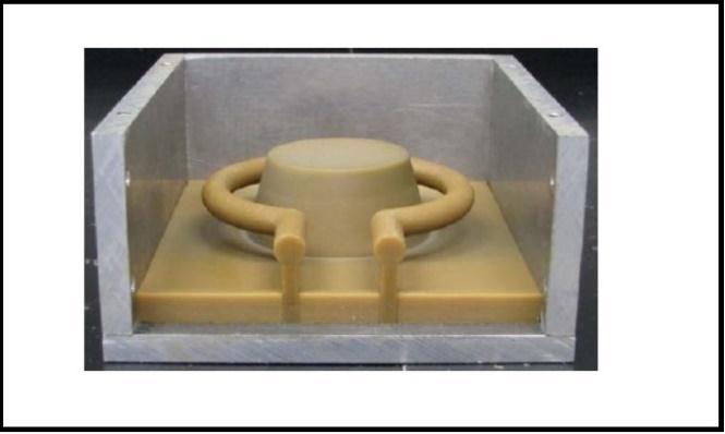
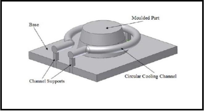
Above are channel and moulded parts such as mould equivalents in terms of dimensions and location relative to cavity and base. Solid pattern model for channel and resultingmouldedpartsinRPFigure5depictstheCCCCCAD model, Figure 7 depicts the PCCC CAD model, and Figures 6 and 8 depict the appropriate wax models. Thermo jet's 3D printerproduceswaxmodels.Figures5
Figure 6: Circularchannelpatternassemblyinsidecasting frame
2.4. Cooling Pipes Attachment Fabrication
Brassnozzlesconnectcoolanttubestothecirculartunnelof the mold. Brass nozzles are used to connect coolant pipes, but they are incompatible with the profiled channel. Figure 11 depicts how to attach pipes to moulded channels. The ends of this structure are contoured and rounded. Epoxy moldsprintedin3D.Aftertheepoxyhardens,itwillbeused to construct the nozzle attachment for the finished product. Alongthecircularridgeofthemold.
2.5. Yu Wang, Kai-Min Yu1, Charlie C.L.Wang
Figure 5: Circularchannelpatternassembly
2.3. Epoxy Casting Of Mould Cavities And Core
Aluminumframesholdepoxy-castingpatterns.Figures6and 8showpatternstructure.Aluminum-filledepoxyresinswere employed for the injection mold cavity and core. After degassing,analuminumframewasepoxy-coated.Epoxywas cured as instructed. During the final cure cycle (Annex), pattern wax melts out of epoxy, leaving the mold cavity and coolingchannels.
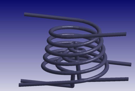
A cooling channel for thermoplastic infusion improves the form plan. Conformal cooling channels have the potential to improve mold effectiveness and quality. The procedure for winding a conformal cooling channel is described in this paper. Our cooling pipe computation has basic availability and can achieve conformal cooling in complex configurations. Bends hub cooling channels adhere to the freestyle surface of the shape. A limit separation guide was used equitably in the computation for supplying a winding bend on a superficial level. Cooling channels with minimal flowslowdownarecreatedbyconformalwindingintoplastic parts.Asaresult,coolingpathwayscanbeuniform.Because it is readily available, this winding channel can be made by bowingratherthanlasersintering.
2.6. Hong-Seok Park, And Xuan-Phuong Dang
Researchers and form designers understand the importance of freezing during infusion molding. To improve cooling architecture,plasticinjectionsarebeingused.Thefirstgroup modernizes traditional cooling channels (bored straight conduits), while the second creates infusion form cooling channels. It is discussed how to reduce the size and area of coolinglineswhilealsostreamliningthecooling framework.
International Research Journal of Engineering and Technology (IRJET) e-ISSN:2395-0056
Volume: 09 Issue: 11 | Nov 2022 www.irjet.net p-ISSN:2395-0072
The following meeting discussed how to create conformal coolingchannelsthatadapttotheformdepressedsurface,as well as whether the cooling framework is sufficient. This mind-bogglingcoolingframeworkwasnotcreatedusingSFF orrapidprototyping.
SLM,anadditivemanufacturingpowdertechnology,couldbe usedtomakemoldsforconformalcoolinginplasticinjection channels, according to S. Marquesa, A.F. Souzab, J.R. Mirandaa, and R.F.F. Santos. The advantages of conformal cooling for injection molding polypropylene parts are demonstrated in this CAE-simulated study. CAE models contrast the two cooling methods. Conformal cooling was tested and found to improve heat uniformity and cut cycle timeby14%.
3. Problem Definition
Plastics' adaptability improves profits and labour flows in numeroussectors.Theautosectorgainsfromplasticuseand new technologies. Safer, more energy-efficient cars increase jobs and exports. Plastics have many benefits in the vehicle sector.
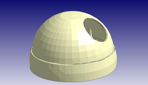
We chose a wall-mounted CCTV camera because it's massproduced and curved. This part is injection molded with a traditional cooling channel, which leads to a longer cycle time.
Conformal cooling solves this challenge by optimizing parametersforbestcomponentquality,reducedcoolingand cycletime.
Simulationincludespartdefect&warpageanalysis.
4. Methodology
4.1. CAD Modelling:
Using SolidWorks' in-built CAD modelling tools to generate thepartorassembly'sgeometry.
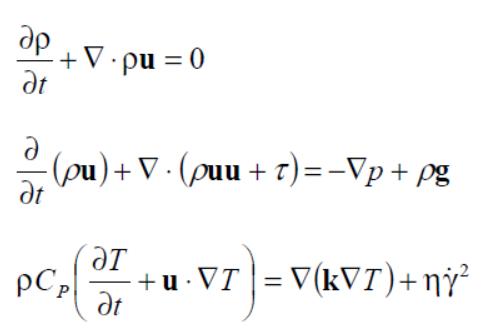
4.2. Governing equation-
4.3. Pre-processing:
Import part/ insert geometry:
International Research Journal of Engineering and Technology (IRJET) e-ISSN:2395-0056 Volume: 09 Issue: 11 | Nov 2022 www.irjet.net p-ISSN:2395-0072


International Research Journal of Engineering and Technology (IRJET) e-ISSN:2395-0056
Volume: 09 Issue: 11 | Nov 2022 www.irjet.net p-ISSN:2395-0072
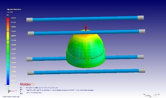
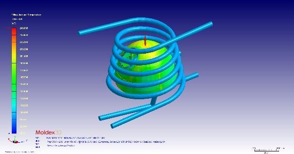
Filling Melt Front Time 4.1sec 3.5sec
Filling Temperature 258.5℃ 253.7℃
Filling Volumetric Shrinkage 8.7% 8.3%
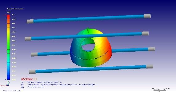
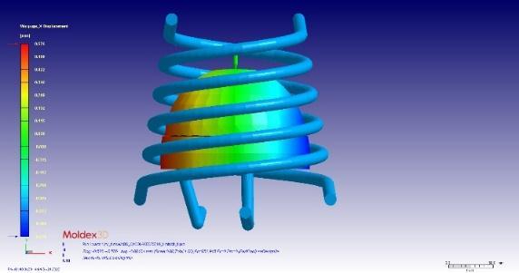
Figure 32: WarpageX-Displacement
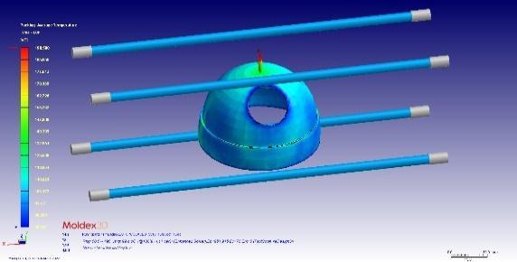
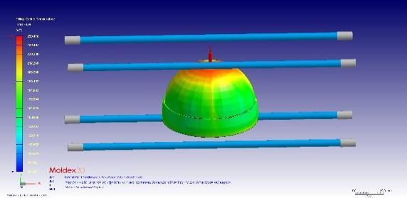
5.3. Comparison Between Conventional and Conformal Cooling
Table 1:
Parameter
ComparisonBetweenCooling
Conventional Cooling Result Conformal Cooling Result
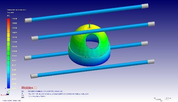
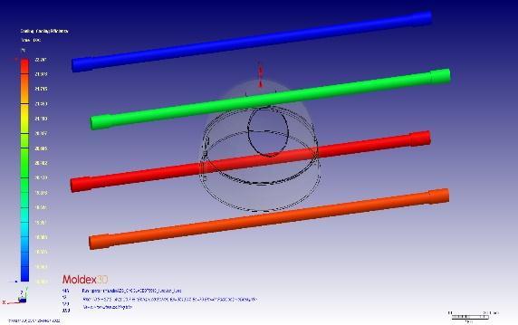
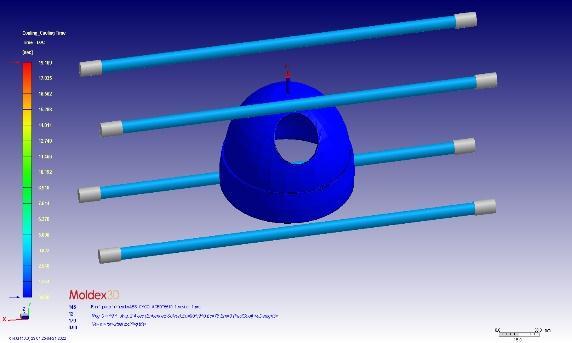
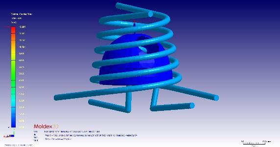
Coolingtime 19.1sec 13.2sec
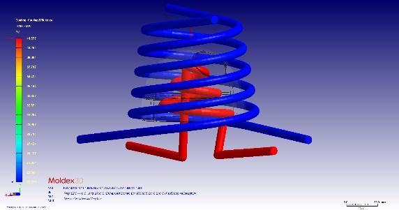
Cooling efficiency 22.24% 41.57%
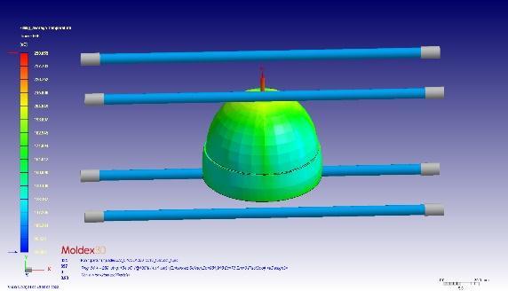
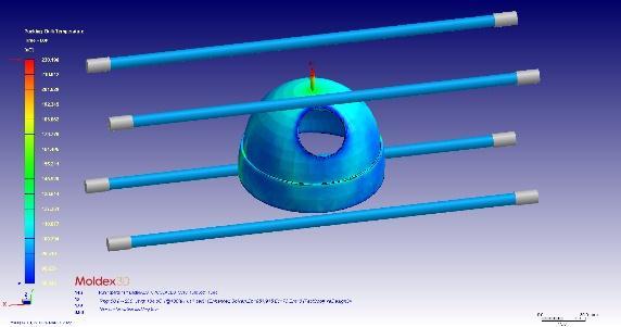
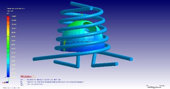
Average temperature 128.7℃ 110.06℃ Centre temperature 135℃ 120.08℃
Coolingtime 19.1sec 13.2sec
Table 2: ComparisonBetweenFilling
Parameter
Conventional Cooling Result
Conformal Cooling Result
Filling Average Temperature 258.6℃ 248.9℃
Filling Bulk Temperature 255.6℃ 249.1℃
Filling Center Temperature 250.5℃ 241.5℃
Filling Max. Shear Rate 926.2(1/sec) 100.7(1/sec)
Filling Max. Shear Stress 9.453 MPa 5.1MPa
Filling Melt Front Temperature 251.8℃ 262.9℃
Table 3: ComparisonBetweenPacking Parameter Conventional Cooling Result
Conformal Cooling Result
Packing Average Temperature 198.5℃ 185.8℃
Packing Bulk Temperature 230.2℃ 222.4℃
Packing Center Temperature 237.8℃ 230.3℃
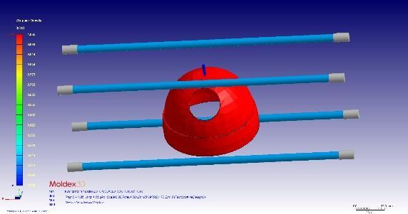
PackingDensity 1.01g/cc 3.05g/cc
Packing Max. Temperature 249.4℃ 239.5℃
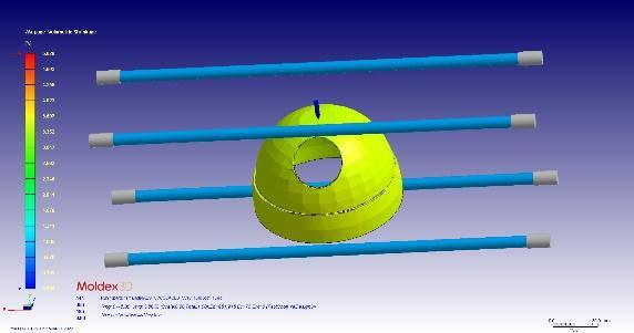
Packing Max. VolumeShrinkage 8.3% 5.4%
Packing Melt FrontTime 4.1sec 3.4sec
Packing Melting Core 255.4℃ 245.4℃
PackingPressure 27.03MPa 25.4MPa
Table 4:ComparisonBetweenWarepage
Parameter
Conventional Cooling Result
Conformal Cooling Result
Warpage Density 1.05g/cc 0.99g/cc
Warpage Flatness 5.028% 4.519%
Warpage Volumetric Shrinkage
0.61mm 0.57mm
International Research Journal of Engineering and Technology (IRJET) e-ISSN:2395-0056
Volume: 09 Issue: 11 | Nov 2022 www.irjet.net p-ISSN:2395-0072
Warpage XDisplacement 11.72 0.37
Warpage YDisplacement 9.04 0.59
Warpage ZDisplacement 1.05g/cc 0.99g/cc
6. Conclusion
Shorten Cooling Time
Conformalcoolingchannelprovidedbetterheatcontrolthan standard cooling channel and one without cooling channel, reducing cooling time by 70.03 and 90.26 percent, respectively.
Quality Prediction
The temperature difference between the upper and lower depressionwallswasreducedby99.5%withcoolingtubes.
7. Future Aspects
IntroducingaBefellSystemincoolingchannels. CleaningofConformalcoolingchannels.
8. References
[1]. Ajay Malviya1, Rahul Patil2, Ankit Shrivastav3, “Scope Of Additive Manufacturing In Wind Energy Systems, International Conference On “Recent Advances In Renewable Energy Sources” Rares 2021 (February 27, 2021) EMail:Ajay.Malviya830@Gmail.Com,Http://Dx.Doi.Org /10.2139/Ssrn.3812137, Ssrn: Https://Ssrn.Com/Abstract=3812137”
[2]. Prashant Paraye1, Dr. R.M. Sarviya2, “Review Of Efficient Design Of Heat Exchanger By Additive Manufacturing, International Conference On “Recent Advances In Renewable Energy Sources” Rares 2021 (February 26, 2021). EMail:Paraye.Prashant@Gmail.Com, Http://Dx.Doi.Org/10.2139/Ssrn.3808984, Ssrn: Https://Ssrn.Com/Abstract=3808984”
[3]. Prashant Paraye1, Gajanan Pradhan2, Ajay Malviya3, “Reverse Engineering Implementation In Cae Analysis, International Research Journal Of
EngineeringAndTechnology(Irjet)MobileNo.:+917509935255, +91-8305715740, E-Mail: Paraye.Prashant@Gmail.Com, Ajay.Malviya830@Gmail.Com, E-Issn: 2395-0056 Volume: 07 Issue: 08 | Aug 2020 Www.Irjet.Net PIssn:2395-0072”
[4]. Saransh Gupta1, Prashant Paraye2, Ajay Malviya3, Mohsin Khan4 Injection Molding, Packing Phase Analysis On Conformal And Traditional Cooling Channels, International Journal Of Creative Research Thoughts(Ijcrt),|Volume9,Issue6June2021|Issn: 2320-2882
[5]. E. Dimla, M. Camilotto, F. Miani (15 May 2005). "Design And Optimisation Of Conformal Cooling Channels In Injection Moulding Tools".Journal Of Materials Processing Technology. 164–165: 1294–1300.Doi:10.1016/J.Jmatprotec.2005.02.162.
[6]. J.C.Ferreira,A.Mateus(25November2003)."Studies Of Rapid Soft Tooling With Conformal Cooling Channels For Plastic Injection Moulding".Journal Of Materials Processing Technology.142(2): 508–516.Doi:10.1016/S0924-0136(03)00650-2.
[7]. K W Dalgarno, T D Stewart, 2001 Manufacture Of Production Injection Mould Tooling Incorporating Conformal Cooling Channels Via Indirect Selective Laser Sintering,Proceedings Of The Institution Of Mechanical Engineers,PartB:Journal OfEngineering Manufacture,215,1323-1332,
[8]. [21] Au K. M., Yu K. M. (2007). "A Scaffolding Architecture For Conformal Cooling Design In Rapid PlasticInjectionMoulding".TheInternationalJournal Of Advanced Manufacturing Technology.34(5–6): 496–515.Doi:10.1007/S00170-006-0628-X.
[9]. Park H. S., Pham N. H. (2009). "Design Of Conformal Cooling Channels For An Automotive Part".International Journal Of Automotive Technology.10(1): 87–93.Doi:10.1007/S12239009-0011-7
[10]. Au K.M., Yu K.M. (2011). "Modeling Of MultiConnected Porous Passageway For Mould Cooling".Computer-Aided Design. 43 (8): 989 1000.Doi:10.1016/J.Cad.2011.02.007. Hdl:10397/18 795.
[11]. AuK.M.,YuK.M.(2006)."VariableRadiusConformal Cooling Channel For Rapid Tool".Materials Science Forum. 532–533: 520–523.Doi:10.4028/Www.Scientific.Net/Msf.532533.520.Hdl:10397/28534.
[12]. Au K.M., Yu K.M. (2014). "Variable Distance AdjustmentForConformalCoolingChannelDesignIn Rapid Tool".Journal Of Manufacturing Science And Engineering 136 (4): 044501.Doi:10.1115/1.4026494.
[13]. Maw-Ling Wang, Rong-Yeu Chang, Chia-Hsiang (David)Hsu,MoldingSimulation:TheoryAndPractice, Editor(S): Mawling Wang, Rong-Yeu Chang, ChiaHsiang (David) Hsu, Molding Simulation: Theory And Practice, Hanser, 2018, Pages Ixviii, Isbn 9781569906194, Https://Doi.Org/10.3139/9781569906200.Fm
[14]. R. B. Bird, W. E. Stewart, E. N. Lightfoot, Transport Phenomena, Revised 2nd Ed., New York, Usa: John Wiley&Sons,(2007).
[15]. S.Ahn,S.T.Chung,S.V.Atre,S.J.Park&R.M.German (2008) Integrated Filling, Packing And Cooling Cae AnalysisOfPowderInjectionMouldingParts,Powder Metallurgy, 51:4, 318-326 Http://Dx.Doi.Org/10.1179/174329008x284903
[16]. Christoph Froehlich, Wolfgang Kemmetmüller & Andreas Kugi (2018): Control-Oriented Modeling Of Servo-Pump Driven Injection Molding Machines In The Filling And Packing Phase, Mathematical And Computer Modelling Of Dynamical Systems, Doi: 10.1080/13873954.2018.1481870
[17]. Http://Support.Moldex3d.Com/R15/En/Index.Html? Postprocessing_Resultinterpretations_Analysislog.Ht ml
International Research Journal of Engineering and Technology (IRJET) e-ISSN:2395-0056 Volume: 09 Issue: 11 | Nov 2022 www.irjet.net p-ISSN:2395-0072 © 2022, IRJET | Impact Factor value: 7.529 | ISO 9001:2008 Certified Journal | Page656