
International Research Journal of Engineering and Technology (IRJET) e-ISSN:2395-0056
Volume: 12 Issue: 05 | May 2025 www.irjet.net p-ISSN:2395-0072
DESIGN AND FABRICATION OF SOLAR POWERED OVER HEAD CRANE FOR LOGISTICS VEHICLE
Ankit Singh1 Assistant Professor, Tushar Trivedi2, Khushi Rajput3
U.G Student, Department of Mechanical Engineering Axis Institute of Technology and Management Kanpur, Uttar Pradesh (209402), India
Abstract Material handling is a common challenge in manyindustries,leadingto theuseofcranesandElectric OverheadTraveling(EOT)systems.Thisprojectpresents a solution by designing an overhead crane that is built into a truck trolley. This system helps move heavy loads fromoutsidethetrucktoinsideandalsowithinthetruck. The overhead crane extends beyond the truck’s chassis, makingiteasytolift nearby loadsandplacetheminside. Itcanmoveinall three directionsand runsona batterypowered motor. To improve efficiency, a solar panel is also installed as a backup power source. This system reduces manual labor, speeds up loading and unloading, andlowerscosts. Thistypeofcraneisespeciallyusefulin construction, the oil and gas industry, and railway logistics, where moving heavy loads is a challenge. By adding an overhead crane to a truck, this system makes materialhandlingsafer,faster,andmoreefficient.
Keywords: Gantry,Hoist,Boom,Carriage,Trolley,Bridge Cranesetc.
I. INTRODUCTION
An overhead crane is a machine used to lift, move, and lower heavy objects in places like factories, warehouses, shipyards, and construction sites. It has two main tracks called runways, with a bridge that moves between them. This allows the crane to lift and transport loads in different directions. The key parts of an overhead crane include the bridge, which spans the work area, and the runway, which supports the bridge. The hoist is the part thatliftsandlowerstheload,whilethetrolleycarriesthe hoist and moves along the bridge. End trucks help support the bridge, and the crane is controlled either manually,witharemote,orautomatically.Safetyfeatures like limit switches, overload protection, and emergency stopbuttonshelppreventaccidents.
There are different types of overhead cranes. Single girder cranes have one main beam and are used for lighterloads,whiledoublegirdercraneshavetwobeams and can lift heavier loads. Gantry cranes have legs and moveontracksorwheels,whilejibcraneshavearotating armforliftingobjectsinasmallarea.Monorailcranesuse afixedtrackformovingitemsinastraightline.Overhead cranes are very useful because they reduce the need for manual lifting, making work faster and safer. They also save space by using overhead areas and can handle very
heavy loads with ease. This helps businesses improve productivityandreducecostsinthelongrun.
These cranes are used in many industries, such as manufacturingplantsformovingmaterials,warehousesfor storing and transporting goods, and steel factories for handling heavy metal items. They are also important in construction for lifting materials and in shipbuilding for assembling and maintaining large ships. Overall, overhead cranes help make work easier, safer, and more efficient. Regular maintenance and proper training are necessary to ensuretheyworkwellandlastalongtime.
1.1 Evolution of Mobile Cranes
Mobile cranes have changed a lot over time, becoming more powerful, efficient, and easy to use. They started as simple manual machines and have evolved into advanced, computer-controlledliftingsystems.
Early Mobile Cranes
In ancient times, people used wooden cranes with ropes and pulleys to lift heavy objects. The Romans built mobile cranes on carts to move materials for roads and buildings. During the medieval period, treadwheel cranes (powered by people walking inside a wheel) helped in construction, buttheywerestilldifficulttomove.
Steam-Powered Cranes (18th–19th Century)
The Industrial Revolution brought steam-powered cranes, makingliftingeasierandmoreefficient.Thesecraneswere oftenmountedonrailwaysforloadingandunloadingcargo. British engineer William Armstrong developed hydraulic andsteam-poweredcranes,improvingliftingcapacity.
Diesel and Electric Cranes (20th Century)
In the early 1900s, diesel and electric engines replaced steam,leadingtotruck-mountedcranes.Hydraulicsystems were introduced, allowing smoother and more controlled movements After World War II, rough-terrain and telescopic boom cranes were developed, making cranes moreversatile.
International Research Journal of Engineering and Technology (IRJET) e-ISSN:2395-0056
Volume: 12 Issue: 05 | May 2025 www.irjet.net p-ISSN:2395-0072
Modern Mobile Cranes (21st Century)
Today, mobile cranes use advanced technology like GPS, remote controls, and artificial intelligence to improve safetyandefficiency.Hybridandelectric-poweredcranes are being developed to reduce fuel use and pollution. Somecompaniesarealsoexploringsolar-poweredcranes foragreenerfuture.
1.2 Types of Over Head Cranes
Overhead cranes are widely used in industries to lift and transport heavy materials efficiently. They come in different types, each designed for specific applications basedonloadcapacity,structure,andoperationalneeds.
1.2.1
Bridge Cranes
Bridge cranes are the most common type, featuring a horizontal bridge that spans the width of a workspace. They are supported by either a building structure or freestanding columns. Single girder bridge cranes have only one main girder supporting the hoist, making them cost-effectiveandlightweight,typicallyhandlingloadsup to20tons.Theyarecommonlyusedinwarehouses,small manufacturing plants, and assembly lines. Double girder bridge cranes, on the other hand, have two girders, providing increased strength and stability, and are suitableforheavy-dutyapplications,often exceeding100 tons.
Components of Bridge Cranes
Bridge cranes consist of several key components, including the bridge, girders, hoist, trolley, and end trucks. The bridge is the horizontal beam that spans the workspace, while the girders are the main structural members that support the hoist. The hoist is the device that lifts and lowers loads, and the trolley is the mechanismthatmovesthehoistalongthebridge.
1.2.2
Gantry Cranes
Gantry cranes are another type of overhead crane, supported by legs that move on rails or wheels, making them suitable for outdoor and large open-space applications. Full gantry cranes have two vertical legs supporting the bridge and can handle extremely heavy loads, sometimes over 200 tons. Semi-gantry cranes, on the other hand, have one side supported by a leg on the ground, while the other side is attached to an existing structure,suchasawallorcolumn.
Types of Gantry Cranes
Portable gantry cranes are small, mobile cranes that can be easily moved and assembled, typically used for lightduty applications in workshops and maintenance areas, with a lifting capacity of up to 10 tons. Gantry cranes
consist of several key components, including legs, bridge, hoist,trolley,andwheelsorrails.
1.2.3 Jib Cranes
Jib cranes consist of a horizontal boom (jib) that rotates around a central point, making them ideal for localized liftingoperations.Free-standingjibcranesaremountedon a vertical post and can rotate 180° to 360°, handling up to 15 tons. Wall-mounted jib cranes are attached to a wall or an existing column, saving floor space while providing liftingcapabilitiesupto5tons.
1.2.4 Monorail Cranes
Monorail cranes feature a single rail along which the hoist moves in a fixed path, commonly used in assembly lines and manufacturing processes. They are simple in design, cost-effective,andsuitableforlinearliftingtasks.
II. Objective
The aim of this project is to design and fabricate a solarpowered overhead crane inside a truck, providing an efficient and eco-friendly solution for lifting, moving, and unloading heavy materials. The crane will be integrated withinthe truck toallow easytransportationandhandling of loads without requiring external lifting equipment. This project will focus on determining the maximum load capacity the fabricated crane can safely lift and operate without causing structural failure or affecting the truck’s balance. A detailed analysis of the normal reaction forces acting on the wheels of the truck will be conducted to ensure that the additional load does not compromise the vehicle’s stability, maneuverability, or suspension system. Another critical aspect of the project is the calculation of theminimumtorquerequiredtoliftaspecificload,whichis essential for selecting the right motor, gearbox, and pulley system. By optimizing these mechanical components, the crane can operate efficiently while minimizing energy losses. The study will also compare the performance and efficiency of the solar-powered crane with a traditional electricallypoweredindustrialoverheadcrane,considering key factors such as power consumption, lifting speed, operationalfeasibility,andload-handlingcapability.
Thiscomparisonwillhelpinunderstandingtheadvantages and limitations of using solar energy for material handling applications. Furthermore, the project will explore the structural design, material selection, and energy management system to enhance the durability and efficiency of the crane. The integration of solar panels, batteries, and electrical components will be examined to ensure a reliable power supply for continuous operation. The findings of this study will contribute to the development of a sustainable, energy-efficient, and costeffective lifting solution that can be used in industries wheremobilityandflexibilityarecrucial.
International Research Journal of Engineering and Technology (IRJET) e-ISSN:2395-0056
Volume: 12 Issue: 05 | May 2025 www.irjet.net p-ISSN:2395-0072
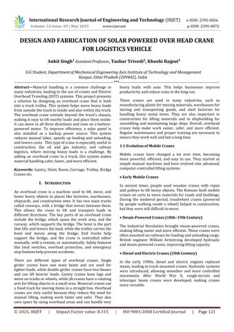
andAnalysisofasolar-Powered
The primary objective of this research paper is to design and develop a solar-powered overhead crane specifically for logistics vehicles. The aim is to create an efficient, cost-effective, and environmentally friendly solution for lifting and moving heavy loads. Traditional overhead cranes typically rely on electricity or fuel-powered engines, which lead to high operational costs and increased carbon emissions. By using solar energy, this study explores a sustainable alternative that reduces energy costs and minimizes environmental impact while maintaininghighperformance.
The research involves designing a sturdy and efficient cranesystemthatcanliftandtransportheavygoodswith minimal energy consumption. This includes selecting suitable materials, integrating solar panels for power generation, and implementing a reliable control system for safe and smooth operation. The fabrication process requires careful planning to ensure that the crane is lightweight yet strong enough to handle heavy loads. Factors such as weight distribution, structural stability, andenergyefficiencyareconsideredindetailtooptimize performance.
Once fabricated, the crane is tested under real-world conditions to evaluate its lifting capacity, power efficiency, and operational reliability. The study also examinespotentialchallenges,suchasenergystoragefor nighttime operation and the durability of solar panels in differentweatherconditions.Byaddressingthesefactors, theresearchaimstodevelopapracticalsolutionthatcan be widely used in warehouses, factories, and logistics hubs. Ultimately, this project contributes to the advancementofsustainablematerialhandlingsystemsby promoting the use of renewable energy in industrial applications. The solar-powered overhead crane offers a cleaner and more cost-effective alternative to conventional lifting systems, helping businesses reduce their carbon footprint while improving operational efficiency. This research highlights the potential of solar
energy in industrial logistics and encourages further innovationingreentechnologyformaterialhandling.
III. Design and methodology
3.1
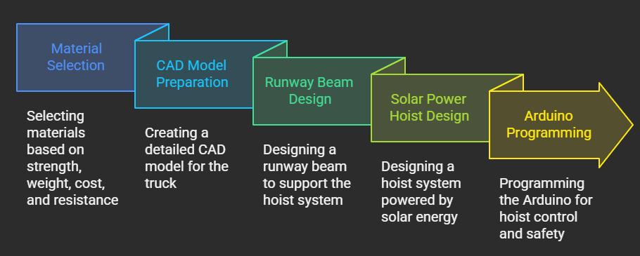
Introduction to design
In this chapter design of over head crane and logistic vehicleisperformed.FirstwehavedevelopedaCADmodel with the help of CATIA V5 software. For design, of various partsandcomponentsinthisproject,Wehavetakenmany design consideration such as selected material should be posses more strength by which it can be bear the load of complete model, a number of components attached with overhead crane should be light in weight, economical and durable.
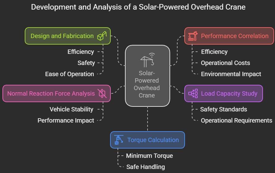
3.2 Design Procedure
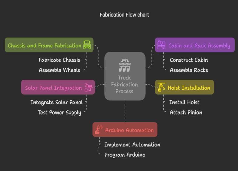
Ihestepsaredescribeintheflowchart.
1. Our first step was to design the vehicle's body. For the vehicle'sbody,wechoseplywoodthatisstrong,capableof carryingtheweightofthecompletecraneassemblyandthe loaditwilllift.
2. In the second step we designed the vehicle cabin made up of a solid material, which will be assembled with the vehicle body. The cabin consists of two pockets for the windowsandoneforthefront.
3.Forrunningoftheoverheadcranewedesignedrackand pinion gear using rectangular pattern. This will help in moving the over head crane on the rack in CATIA commandssuchasrectangle,pad,pocket,circle,arc,linear pattern and rectangular pattern. This will help in moving theoverheadcraneontherackinhorizontaldirection.
4. Our over head crane design includes the design of the spool on which a rope will wrap around, the shaft for connectingthepinion,thebed,themotorbrackets,andthe hook design. Assembling these parts will form a complete overheadcrane.
5 In the last step all parts will be assembled together and shows the design of over head crane and the vehicle in we havetoinstallthecrane.
International Research Journal of Engineering and Technology (IRJET) e-ISSN:2395-0056
Volume: 12 Issue: 05 | May 2025 www.irjet.net p-ISSN:2395-0072
4.2 Hoist
Aload-bearingbeamthatspansthebuildingwidth.Iltisthe main structural component that connects the track and moves the forklift back and forth through the carriage. Bridges can consist of one or two beams, commonly referred to as single-girder or double-girder structures. The beam can be made of rolled steel by welding it to a steelcrate.
4.3 Bridge
3.3 Part Design
3.3.1 Design of Cabin
First We designed a cabin for a vehicle in which the overhead crane will be installed. This cabin is designed with many commands such as line, circle, trim, shell, pocket, pad. The specifications of the cabin are : Thickness of wooden sheet used here for the fabrication of the cabin (4cm), Length of cabinet (22am), height of thecabinet(30cmn),widthofcabinet(22cm).
4. Basic Component of Over Head Crane
4.1 Hook
Lifting hooks are used to hold and lift loads using a forkliftorcrane.Liftinghooksareusuallyequippedwitha safetydevicetopreventtherope,chainorcableto which theloadisattachedfrombecomingdetached.Ahoistlifts, holds, raises or lowers a load by steel rope or chain. Hoists can be operated either manually, electrically or with compressed air (pneumatic). The carriage supports the hoist and moves horizontally along the crane bridge todeploythehoistandhook.
Thebridgeisthemainstructureofanoverheadcranethat movesalongthelengthoftheworkarea.Itspansacrossthe widthofthespaceandsupportstheliftingmechanism.The bridge allows the crane to transport heavy loads from one point to another. Aload-bearing that runsthe width of the building. This is the primary structural component that connects the runways and moves the hoist forward and backwardusingatrolley.
4.4 Runway Rail or Tracks
Abridgecanbecomprisedofoneortwobeamsmoreoften referred to as a single girder or double girder design Girderscanbemadeofrolledsteel orcan befabricatedby welding the beams into a steel box design. Rail supported by the runway on which the crane travels. Top-running cranes typically run on ASCE/railroad rails. Gantry cranes canalsoutilizearailortracksysteminstalledinthefloorto movethebridgebackandforth.
4.5 Controls
The controls are usually panel mounted on the crane or hoist and allow the operator to control the crane via an overhead or remote radio console. The control unit can drive a variable frequencydrive(VFD)tocontrol thedrive andliftmotorsandadjust
theliftspeedforaccurateloadsensing. Operatesthecrane and includes pendant controls, radio remote controls, or a cabinforanoperator.
4.6
Electrification
Insulated conductor bars or festoon systems (flat cables) bringpowertothecranefromthebuilding.
When we installed a crane before we must consider some parameters
Motionofthecranestructure.
Weightandtypeofmaterial/load.
Locationofthecrane indoorsoroutdoors.
Requiredcapacity.
Howoftenthecranewillbeused.
Lengthorspanofthecrane.
V. Fabrication Process
5. Fabrication Process
5.1 Introduction
Fabrication of overhead crane for logistics vehicle contains many steps which are following in this chapter. The complete fabrication is fitted as our design consideration. There are many materials are used in fabrication of solar powered overhead crane for logistics vehicle,whicharelistedbelow.
5.3 Fabrication Process
We fabricate a solar powered overhead crane for logistics vehicles using all the above materials. We prepared some parts and assembled them with prototype. Our complete fabricated prototype consists of many parts, and then all parts are fabricated together, and we prepare our prototype. In order to fabricate a solar powered overhead crane for a logistic vehicle, weplan to follow the following steps:
• First we prepare the chassis of the vehicle on which we mount the complete vehicle. This chassis is made from waste iron rods. Grinding, surface finishing and welding processes are used for the fabrication of the cassis of the vehicle.
•With the help of wooden plywood, we prepared a vehicle body that will hold the load of the overhead mounting A woodenplyisattachedwithadhesive,hardnar,andnails.It isusedtocarrygoodsandproducts.
•ThecabinofthevehicleispreparedwithwoodenplyThis wooden ply IS fixed with adhesive, hardner and the nails. Cabin has three slots for windows and front glass. Acrylic sheetscovertheseslots.
Inthisstepthefabricationoftheoverheadframeisdone. Aslot isgiven tothebed where thewire orthe ropewill be passed through. Under the overhead bed, there are fourbracketsforholdingtheshafts.Twobracketscontrol thepinons,whiletwobracketscontrolthepulley
The shaft on which the pulley will be mounted is prepared in this step. This shaft is prepared with waste iron rebers. There are many processes included in the preparation of the shaft such as drilling, turning and grindingforthesurfacefinish.
Assembly of vehicle Containschassis,body,cabin,shafts, rack base, rack, gear and wheels. The chassis contains fourwheelsandDCmotorswhichdrivethevehicle.These all parts assemble together and build the vehicle. These parts are fixed together by nuts and bolts, nails and adhesives.
Assembly of overhead crane, there are a number of componentsincludingabed,shafts,spool,stepper motor and DC motor. The pinions are connected to the stepper motors.ADCmotorisusedtorotatethespool.
International Research Journal of Engineering and Technology (IRJET) e-ISSN:2395-0056
Volume: 12 Issue: 05 | May 2025 www.irjet.net p-ISSN:2395-0072
5.4 Fabricated Prototype
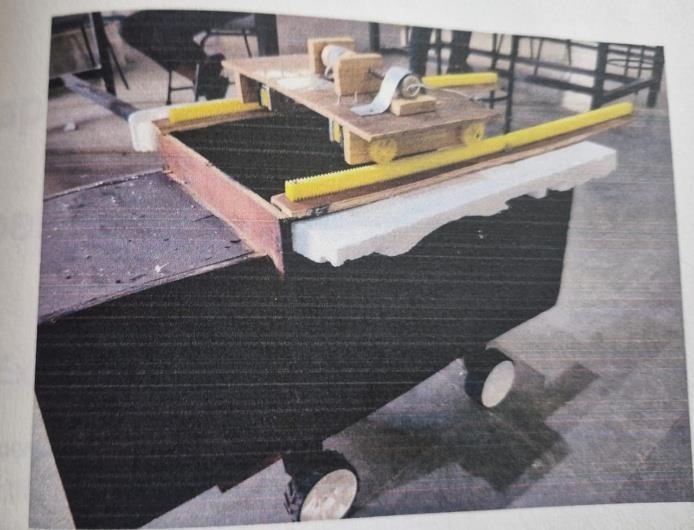
Prototype
VI. Experimental Analysis
6.1 Experimental Setup
In this experimental setup, an overhead crane is used to handle material on a logistics vehicle. In this case, the rope extends to reach the location of the material. Automationcontrolsthemotionoftheropeandoverhead crane. In our experiment, various dead loads are applied on hook and material handling capabilities of vehicle is investigated.Thefabricatedoverheadcraneassemblycan crawl on the guided rack base after lifting the load. We have considered some parameters such as load of material,motortorque,tensioninropeandtimetakenfor thecompleteprocess.
6.1.1 Experimental process
Wefollowedmanystepsforexperimentalcomputationof various analysis such as experimental study of normal reaction force acting on the wheels of vehicle when the overhead crane is at the center of the vehicle or the overheadcranereachesitslimitsorcenterofthevehicle.
Experimentalcomputationofforceequilibriumequation:
Whenoverheadcraneinsidethevehicle.
Whenoverheadcraneoutsideofthevehicle.
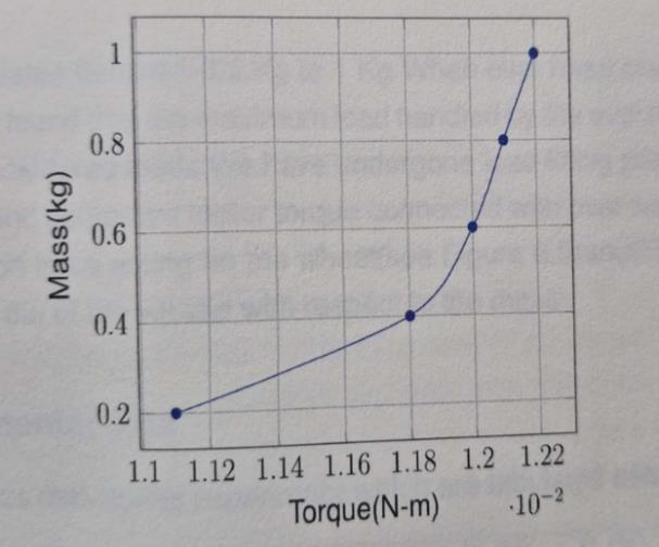
6.1.2 Experimental study on torque of the motor
The torque of motor variate with respect to the hanging load on the over head crane. As our consideration the motor torque should be greater than the the product of moment of inertia and the angular momentum of the pulley.

oftheMotor
6.1.3 Experimental study on normal reaction force at wheels
Normal reaction force by means of a force acting perpendiculartotwosurfacesincon- tactwith eachother. Here we compute normal reaction forces, acting on front wheel of the vehicle while lifting the material by the various loads. Here wefound that different reaction forces areactinginwheelswhilehandlingdifferenttypesloads.
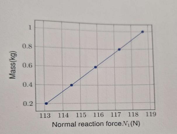
6.1.4 Experimental data
We obtain various data during experiment which are tabulatedbelow:
Table6.1:Experimentaldata
International Research Journal of Engineering and Technology (IRJET) e-ISSN:2395-0056
Volume: 12 Issue: 05 | May 2025 www.irjet.net p-ISSN:2395-0072
6.2
Result and conclusion
Upon performing a set of loading and unloading processes at over head crane based logistics vehicle, It has been observed that variation of lifting LSD may change the stability of vehicle. increasing the dead load increases the normal reaction at rear wheel which may tilt the vehicle backward if the normal reaction at front wheel vanishes hence appropriate stability dead load shouldbeplacedatfrontchassisofvehicle.
Further the operational capability of motor also depends upon (motor for lifting load) depends upon voltage supplied by battery or torque by engine. W With our experimental observation the prototype model is found satisfactoryoperatetoloaduptill1kg.More generalized vehicle model can be devised for centering logistics load. Apartfromthesehydraulicramsshouldalsobeprovided ofthebacksidepfchassistoreducehighernormalloadat rearwheel.
6.2.1
Future Outlook
Overhead cranes play an important role in logistics and material handling operations, allowing for efficient movement of goods and materials within a facility. The futureOutlookforoverheadcranesinlogisticsvehiclesis positive, as the demand for faster and more efficient materialhandlingcontinuestogrow.
Many companies are looking to automate their material handling operations to increase efficiency, reduce costs andimprovesafety.Thiscouldleadtothedevelopmentof more advanced overhead crane systems that are integrated with automated material handling systems, such as conveyor belts and robotic picking systems, Another trend that is likely to impact the future of overhead cranes is the increasing use of data analytics and loT technologies in logistics. By collecting and analyzing data on material handling operations, companies can identify areas for improvement and
optimize their processes for greater efficiency. This could leadtothedevelopmentofoverheadcranesystemsthatare equippedwithsensorsandotherloTdevicestocollectdata ontheirperformanceandusage,Overall,thefutureoutlook foroverheadcranesinlogisticsvehiclesispositive,asthey willcontinuetoplayanimportantroleinmaterialhandling operations.Astechnologycontinuestoevolveandlogistics operations become more automated and data-driven, we can expect to see more advanced and efficient overhead crane systems being developed to meet the needs of the industry.
REFERENCES
[1] Akira, ABDE. Anty sway control for over head cranes using neural networks. International journal of innovative, computing, information and control, 7:Pg 4251-4262,2011.
[2] Anjikar, A.D. Design, development of overhead monorail fort material handling system. International Journal of Emerging Technologies in Engineering Research, 3: Pg 475-476,2013.
[3] BASHA, G.MD.JAVEED and RAO, S.KAMALESH. A crane hook's design and stress values calculation. European Journal of Molecular Clinical Medicine, 4 Pg 212-237, 2017.
[4] Bhutta,MuhammadMahmoodAslam;Misbahuddin,Mian Muhammad;Qureshi,MuhammadAsifMahmood;Ahmad, Syed Amjad, and Mughal, Hameed Ullah. Using finite element analysis for design optimization of twin beam cranearm.Scienceinternational,1:Pg131-138,2016.
[5] Devi,Lal;Pabla,Dr.B.S,andSingh,Sh.AtulKumar.Design optimizationofdoublegirderelectricoverheadtravelling crane. International Journal of Emerging Technologies in EngineeringResearch(IJETER),5:124-127,2017.
[6] Gerdemeli, Ismail; Kurt, Serpil, and Yıldırım, Metin. Calculation modeling and analysis with finite element method of rubber tyred container stacking crane. International Research/Expert Conference, 7:545-548, 2010.
[7] Gowtham, MP; Ponsakthivel,; Santhosh,; Prasath, Siva, and Shivaneshan,. Design and fabrication of a single acting hydraulic crane. International Journal of InnovativeResearchinTechnology,8:Pg228-293,2022.
[8] Haas, Trevor Neville. Maximum horizontal longetudinal force due to crane loading using a coupled approach. InternationalJournal(CIVEJ),1:Pg91-101,2014.
[9] Hoon Hoo Lee. Modeling and control of a three dimensional overhead crane. Journal od dynamic system measurement and control, 120:Pg 475-476, 1998. Hoo
International Research Journal of Engineering and Technology (IRJET) e-ISSN:2395-0056
Volume: 12 Issue: 05 | May 2025 www.irjet.net p-ISSN:2395-0072
Lee. Modeling and control of a three dimensional overheadcrane.Journa
[10] kumar Pavan, pratik Naga bhushana rav. Design and dynamic analysis of 120 ton capacity eot crane grider. International Research Journal of Engineering and Technology(IRJET),4:1055-1062,2018.
[11]Leszek, Sowa; Saternus, Zbigniew, and Kubiak, Marcin. Numerical modelling of mechanical phenomena in the gantry crane beam. International Polish-Slovak Confer"Machine Modeling and Simulations 2016, 4:Pg 225232,2017.
[12]Mahesh, Solanki; Bhatt, Antriksh; kumar Rathour, Anil, and Thakkar, Smit. Weight optimization in crane hook. International Journal of Research Development Organisation,1:Pg192-196,2015.
[13] Marijonas, Bogdevièius and Vika, Aleksandr. The dynamics of an overhead crane lifting process in a vertical plane.,International Journal of Emerging Technologies in Engineering Research, 5:Pg 176-180, 2005.
[14]Omkar,SakurikarandKushare,D.V.Reviewofoverhead crane and analysis of components depending on span. International Research Journal of Engineering and Technology(IRJET),6:Pg1004-1008,2016.
[15]Prabhu, Shankar; Saravanakumar,; Surender,, and Nithiyanand,.Analysisofincidentsandimplementation of safety features in eot crane. International Advanced Research Journal in Science, Engineering and Technology,9:Pg485-490,2019.
[16]Ravikanth,Dr.RajuandUpendar.,Somagani.Designand analysis of crane hook. Science international, 5:Pg 2394-0697,2018.
Bibliography

Ankit Singh AssistantProfessor Axis Institute of Technology and Management Kanpur affiliatedfromAKTULucknow(UP)INDIA.

Tushar Trivedi U.GStudent
Axis Institute of Technology and Management Kanpur affiliatedfromAKTULucknow(UP)INDIA.

Khushi Rajput U.GStudent
Axis Institute of Technology and Management Kanpur affiliatedfromAKTULucknow(UP)INDIA.