
International Research Journal of Engineering and Technology (IRJET) e-ISSN: 2395-0056
Volume: 12 Issue: 01 | Jan 2025 www.irjet.net p-ISSN: 2395-0072

International Research Journal of Engineering and Technology (IRJET) e-ISSN: 2395-0056
Volume: 12 Issue: 01 | Jan 2025 www.irjet.net p-ISSN: 2395-0072
Suhail Raza1, Mohd Asif2, Rohit3 , Sushil Kumar4 , Varun Mehra5 , Akhlak Ahamad6
1Student of Bachelor of Technology in Civil Engineering, Lingaya’s Vidyapeeth, Faridabad, India
2Student of Bachelor of Technology in Civil Engineering, Lingaya’s Vidyapeeth, Faridabad, India
3Student of Bachelor of Technology in Civil Engineering, Lingaya’s Vidyapeeth, Faridabad, India
4Student of Bachelor of Technology in Civil Engineering, Lingaya’s Vidyapeeth, Faridabad, India
5Student of Bachelor of Technology in Civil Engineering, Lingaya’s Vidyapeeth, Faridabad, India
6Student of Bachelor of Technology in Civil Engineering, Lingaya’s Vidyapeeth, Faridabad, India
Abstract - Thispaperexaminesthedesignanddetailing of a Ground Floor + 8-story Reinforced Cement Concrete (RCC) framed structure located at Okhla NSIC, New Delhi. Thestructure,withaheightof24meters,isanalyzedwith and without shear walls using ETABS software. Key parameters include concrete grade M20, reinforcement gradeFe415,stiffsoiltype,minimumbaseshearof1323.1 kN, and design base shear of 4162.58 kN. The study evaluates seismic performance, risk assessment, and construction methodologies. Tables and graphs illustrate findings on structural performance and safety. The research emphasizes the importance of shear walls in enhancingseismicresistance.
Key Words: Concrete grade M20, Reinforcement grade Fe415,StiffSoiltype,Minimumbaseshearanddesignbase shear.
Earthquake zoning in India refers to the division of the country into regions based on their vulnerability to seismic activity.Thisclassificationhelpsinunderstanding the potential risk of earthquakes in different areas and guides the development of appropriate construction standardsanddisastermanagementstrategies.
India's zoning system categorizes the country into four seismic zones:ZoneII,Zone III,ZoneIV,andZone V, with Zone II having the lowest seismic risk and Zone V the highest. This classification is based on historical earthquake data, tectonic features, and the intensity of groundshakingexperiencedinvariousregions.
ZoneVincludesareaslikethenortheasternstates,partsof JammuandKashmir,HimachalPradesh,Uttarakhand,and theAndamanandNicobarIslands,whicharehighlyprone to severe earthquakes. Zones IV and III encompass areas with moderate to significant seismic risk, while Zone II coversregionswithrelativelylowseismicactivity.
This zoning framework is critical for implementing building codes and ensuring that infrastructure in highrisk areas is designed to withstand potential seismic forces.
Seismic activity poses significant challenges to building stability, particularly in regions like New Delhi, categorizedunderSeismicZoneIV.Shearwalls,asintegral components of lateral force-resisting systems, play a critical role in mitigating seismic damage in RCC structures.Thisstudycomparestheperformanceofa G+8 RCCframedstructurewithandwithoutshearwalls.Using ETABS software, the paper explores structural behavior, baseshear,storydrift,andstiffnesstoassesstheimpactof shearwalls.
Definition: Shear walls are vertical structural elements designed to resist lateral forces caused by wind and earthquakes. They are crucial in high-rise buildings, providingstiffnessandstability.
Functions:
Resistlateralloads.
Minimizeinter-storydrift.
Enhanceoverallstructuralrigidity.
Placement: Shear walls are strategically located around staircases, elevator cores, and external walls for optimal performancewithoutcompromisingarchitecturaldesign.
India’sseismiczoningisclassifiedintofourzonesbased onearthquakeintensity:
Zone II:Low-intensityearthquakes.
Zone III:Moderate-intensityearthquakes.
Zone IV: Severe-intensity earthquakes (e.g., Delhi).
International Research Journal of Engineering and Technology (IRJET) e-ISSN: 2395-0056
Volume: 12 Issue: 01 | Jan 2025 www.irjet.net p-ISSN: 2395-0072
Zone V:Verysevere-intensityearthquakes.
New Delhi falls under Zone IV, necessitating robust design measures to ensure safety and compliance with IS 1893:2016.
Location:OkhlaNSIC,NewDelhi(SeismicZoneIV).
Structural Details:
Height:24meters(G+8floors).
Concrete Grade:M20.
Reinforcement Grade:Fe415.
Soil Type:Stiff.
Base Shear:
Minimum:1323.1kN.
Design:4162.58kN.
5. METHODOLOGY
5.1 MODELING IN ETABS
TwomodelsarecreatedinETABS:
1. Without Shear Walls: Standard RCC framed structure.
2. With Shear Walls: RCC framed structure incorporatingshearwalls.
Steps:
1. Define material properties (M20 concrete, Fe415 steel).
2. Assign geometric properties (beams, columns, slabs).
3. Applyloads:
Deadloads:Self-weight,floorfinishes.
Liveloads:2.0kN/m².
Seismicloads:AsperIS1893(Part1):2016.
4. Conduct dynamic analysis using the Response SpectrumMethod.
5.2 ANALYSIS PARAMETERS
Natural Period:Calculatedforbothmodels.
Base Shear: Comparison of lateral force distribution.
Story Drift:Evaluatedagainstpermissiblelimits.
Story Stiffness: Assessed for resistance to deformation.
6.1 SEISMIC PERFORMANCE Natural Period:
Without Shear Walls: Higher, indicating lower stiffness.
With Shear Walls: Lower, indicating higher stiffness.
6.2 Displacement
Assessment of displacement table comparing results with and without shear walls at different story levels is given below.
International Research Journal of Engineering and Technology (IRJET) e-ISSN: 2395-0056
Volume: 12 Issue: 01 | Jan 2025 www.irjet.net p-ISSN: 2395-0072
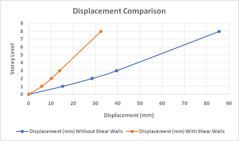
Figure-2: Displacement Comparison Graph
6.3 BASE SHEAR DISTRIBUTION
Shear walls effectively redistribute seismic forces, reducingstressconcentrationsincolumnsandbeams.
6.4 STORY DRIFT
Without shear walls: Drift exceeds permissible limitsinupperstories.
Withshearwalls:Driftremainswithinsafelimits.
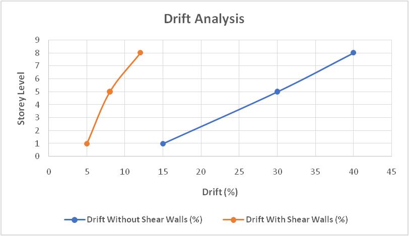
Figure-3: Drift Analysis Comparison Graph
6.5 FAILURE PROBABILITY
The failure probability is assessed based on dynamic responseandriskmetrics:
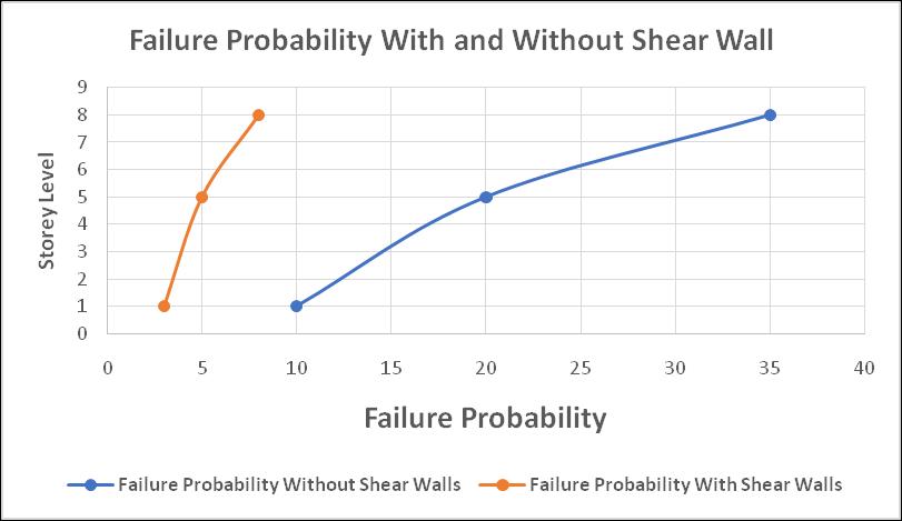
Figure-4: Risk Probability Comparison Graph
6.6 STORY STIFFNESS
Shear walls increase stiffness by approximately 65%, improvingresistancetolateraldeformation.
6.7 RISK ASSESSMENT
Without Shear Walls: Higher vulnerability to seismicforces.
With Shear Walls: Enhanced safety and reduced riskoffailure.
7. CONSTRUCTION METHODOLOGY
7.1FOUNDATION
Raftfoundationdesignedforstiffsoilconditions.
Shearwallsanchoredforeffectiveloadtransfer.
7.2 FRAMING
RCC beams and columns constructed using M20 concreteandFe415steel.
Shear walls integrated with vertical and horizontalreinforcements.
International Research Journal of Engineering and Technology (IRJET) e-ISSN: 2395-0056
Volume: 12 Issue: 01 | Jan 2025 www.irjet.net p-ISSN: 2395-0072
Flat slabs reinforced to resist bending and shear forces.
Vertical reinforcement: 0.25% of the crosssectionalarea.
Horizontal reinforcement: 0.2% of the crosssectionalarea.
Boundary elements: Heavily reinforced to handle concentratedstresses.
8.1 BEAM - COLUMN JOINTS
Specialconfiningreinforcement.
Adequateanchoragetopreventfailure.
8.2 SHEAR WALL REINFORCEMENT
Spacing and placement of bars comply with IS 13920:2016.
9. CONCLUSION
The incorporation of shear walls in RCC structures significantly enhances seismic performance. The study demonstratesthat shear walls reducestory drift,increase stiffness,and distribute lateral forceseffectively, ensuring safety in Seismic Zone IV. ETABS modeling and analysis validate the advantages of shear walls, making them indispensableforearthquake-resistantdesigns.
10. REFERENCES
1. IS 456:2000 - Code of Practice for Plain and ReinforcedConcrete.
2. IS 1893 (Part 1): 2016 - Criteria for Earthquake ResistantDesignofStructures.
3. IS 13920:2016 - Ductile Design and Detailing of ReinforcedConcreteStructures.
4. ETABSSoftwareManual.
11. BIOGRAPHIES


SuhailRaza
Diploma in Civil Engineering from Jamia Millia Islamia, NewDelhi,India,inthebatch of2015-2018.
Bachelor of Technology in Civil Engineering from Lingaya’s Vidyapeeth Faridabad, India, in the batch of2022-2025.


MohdAsif
Diploma in Civil Engineering from Jamia Millia Islamia, NewDelhi,India,inthebatch of2015-2018.
Bachelor of Technology in Civil Engineering from Lingaya’s Vidyapeeth Faridabad, India, in the batch of2022-2025.
Rohit.


Diploma in Civil Engineering from Government Polytechnic Manesar, Gurugram,Haryana,India
Bachelor of Technology in Civil Engineering from Lingaya’s Vidyapeeth Faridabad, India, in the batch of2022-2025.
SushilKumar
Diploma in Civil Engineering from Government Polytechnic Banda, Uttar Pradesh,India.
Bachelor of Technology in Civil Engineering from Lingaya’s Vidyapeeth Faridabad, India, in the batch of2022-2025.
VarunMehra


Diploma in Civil Engineering from Hindu Institute of Technology, Industrial Area, Sonepat,Haryana,India.
Bachelor of Technology in Civil Engineering from Lingaya’s Vidyapeeth Faridabad, India, in the batch of2022-2025.
AkhlakAhamad


Diploma in Civil Engineering from Gandhi Polytechnic Muzaffarnagar, Uttar Pradesh,India.
Bachelor of Technology in Civil Engineering from Lingaya’s Vidyapeeth Faridabad, India, in the batch of2022-2025.