RG140, RG170, RG200
OPERATOR'S COMPARTMENT
GROUP 4
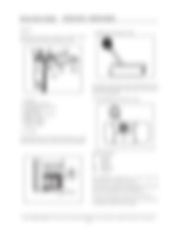
2 - THROTTLE CONTROL LEVER
Dashboard, transmission control lever, throttle control lever, hourmeter, fuse box and master switch.
The engine will remain at low idle with the throttle control lever all the way forward, engine speed will increase as the lever is pulled back. 1- Fuse box 2- Throttle control lever 3- Transmission control lever 4- Switch panel 5- Digital instruments panel 6- Master switch 7- Electric receptacle 8- Ignition switch
3 - TRANSMISSION CONTROL LEVER
1 - FUSE BOX All the grader fuses are installed in the fuse box. For the identification of the fuses, refer to the electrical diagram.
SHIFT PATTERN: RReverse FForward NNeutral DS- Down shift UP- Up shift The transmission control lever is used to select the desired forward or backward speeds. This machine is equipped with an eight (8) speed forward and a four (4) speed reverse transmission. The gear speed change is done using a shift lever. To obtain forward speeds place this lever to the front or to the back to obtain reverse speeds.
Study SAFETY RULES in the front of this manual thoroughly for the protection of machine and safety of personnel. 48


