11 minute read
Group 4

from New Holland RG140 RG170 RG200 RG170 AWD RG200 AWD Road Graders Operator's Manual - PDF DOWNLOAD

RG140, RG170, RG200 OPERATOR'S COMPARTMENT
GROUP 4
Dashboard, transmission control lever, throttle control lever, hourmeter, fuse box and master switch.
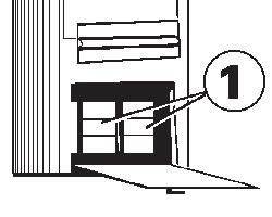
1- Fuse box 2- Throttle control lever 3- Transmission control lever 4- Switch panel 5- Digital instruments panel 6- Master switch 7- Electric receptacle 8- Ignition switch
1 - FUSE BOX
All the grader fuses are installed in the fuse box. For the identification of the fuses, refer to the electrical diagram. 2 - THROTTLE CONTROL LEVER
The engine will remain at low idle with the throttle control lever all the way forward, engine speed will increase as the lever is pulled back.
3 - TRANSMISSION CONTROL LEVER
SHIFT PATTERN: R- Reverse F- Forward N- Neutral DS- Down shift UP- Up shift
The transmission control lever is used to select the desired forward or backward speeds. This machine is equipped with an eight (8) speed forward and a four (4) speed reverse transmission. The gear speed change is done using a shift lever. To obtain forward speeds place this lever to the front or to the back to obtain reverse speeds.
Study SAFETY RULES in the front of this manual thoroughly for the protection of machine and safety of personnel. 48
OPERATOR'S COMPARTMENT RG140, RG170, RG200
By using this lever the proper speed (first, second, etc...) can be selected. Observe the gear display readout for confirmation of the gear selected. If the display shows a "error code" this means that some abnormality has occurred in the transmission system. Therefore it is necessary to contact a New Holland Construction dealer. When the machine is stopped, any gear lower than F3 or R2 may be selected. A single speed change is done with a single push and release of shift lever.
If the shift control lever is pushed and held to the right or left the gear speeds will change automatically.
NEUTRAL LOCK
To move the shift lever out of neutral position, release the "neutral lock" by raising the release ring located under the shift handle knob.
4 - SWITCHES PANEL A- SADDLE LOCK PIN SWITCH
The saddle lock pin switch activates a solenoid valve which sends hydraulic fluid for cylinder rod movements. With ths switch in the "ON" position the pin remains retracted and when the switch is off the pin extend and engage the locator hole. Manipulate blade lift levers to remove or insert pin.
B- RIPPER OR SCARIFIER SWITCH
The ripper or scarifier switch activates a solenoid valve which sends hydraulic fluid either to the rear ripper or to the front scarifier cylinders. To work with ripper, position the switch to the "ON" position and for the scarifier position it to the "OFF" position.
C- MOLDBOARD FLOAT SWITCH (LEFT SIDE)
This switch activates or deactivates the left side moldboard float function. To activate the float function, position the switch to the "ON" position. To deactivate the float function, turn the switch to the "OFF" position.
D- MOLDBOARD FLOAT SWITCH (RIGHT SIDE)
This switch activates or deactivates the right side moldboard float function. To activate the float function, position the switch to the "ON" position. To deactivate the float function, turn the switch to the "OFF" position.
E- FRONT BLADE FLOAT SWITCH
This switch activates or deactivates the front blade float function. To activate the float function, position the switch to the "ON" position. To deactivate the float function, turn the switch to the "OFF" position.
Study SAFETY RULES in the front of this manual thoroughly for the protection of machine and safety of personnel. 49
RG140, RG170, RG200 OPERATOR'S COMPARTMENT
F- MOLDBOARD ANTI-SHOCK FUNCTION SWITCH This switch activates and deactivates the moldboard cylinders anti-shock function. It is an ON/OFF type switch. To activate the anti-shock function, place the switch in the ON position. To deactivate it, place the switch in the OFF position.
4 - SWITCH PANEL (B)
4 - SWITCH PANEL (B) (AWD - OPT)
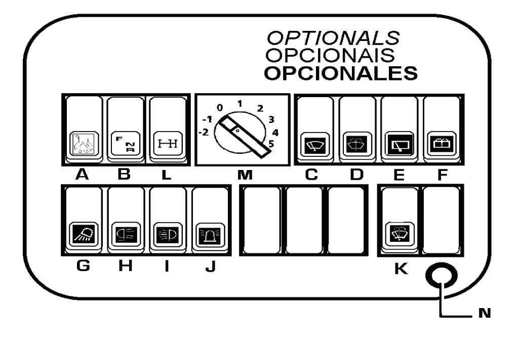
A- NOT USED
B- COME-HOME This switch is located in the lower part of the right console and is used to move the machine in the event of a transmission electronic control unit problem. The switch has three positions: F - forward, N - neutral and R - reverse. The switch must be in the Neutral (N) position with park brake "on" to start the machine.
See "PERIODIC SERVICES" in Maintenance Section.
C- FRONT WINDSHIELD WIPER SWITCH This switch is used to activate the front windshield wiper.
D- FRONT WINDSHIELD WASHER SWITCH This switch is used to activate the front windshield washer. E- REAR WINDOW WIPER SWITCH This switch activates the rear windshield wiper function.
F- REAR WINDSHIELD WASHER SWITCH This switch activates the rear windshield washer function.
G- FLOODLIGHTS SWITCH This switch is used to activate the floodlights.
H- TAIL LIGHT SWITCH This switch is used to activate the tail light.
I- CAB DOME LIGHT SWITCH This switch activates the cab dome light.
J- CAB BEACON LIGHT SWITCH This switch activates the cab beacon light.
K- REAR WINDOW WASHER/WIPER SWITCH This switch activates the rear window washer/ wiper function.
L- FRONT WHEEL DRIVE SWITCH (OPT) This switch activates the optional front wheel drive function.
M- FRONT WHEEL DRIVE SPEED LEVELS This switch adapts the optional front wheel drive to the working and driving conditions independent of rear wheel slip, the speed of the front wheels can be adjusted to eight levels independent of the speed of the rear wheels. The speed levels are selected by means of a rotary switch. Front wheel drive will not operate in eighth gear.
Position 0: Front and rear wheels run at the same speed. Position 1 to 5: Front wheels turning at a higher speed (lead). Each position increases in two percent increments. Position -1 to -2: Front wheels turning at a lower speed (lag). Each position increased in two percent increments. The tractive force of the front axle is reduced.
N- PLUG TO THE EDS TESTER
Study SAFETY RULES in the front of this manual thoroughly for the protection of machine and safety of personnel. 50
5 - SWITCH PANEL (A) OPERATOR'S COMPARTMENT RG140, RG170, RG200
The marker must always register in the green area.
WARNING Do not operate the machine when the gauge is in the red area. Stop the machine and determine the cause of high temperature.
6- MASTER SWITCH
The machine electrical functions can only be actuated if the master switch is in the ON position. When the machine will be parked for a long period of time, turn the master switch to the OFF position.
7- AUXILIARY ELECTRICAL CURRENT RECEPTACLE
The machine is equipped with a 24Vdc auxiliary electrical power supply.
8- STARTING SWITCH
This switch is a rotary type and can be activated by a starting key. It has four positions:
A - ENGINE OIL PRESSURE GAUGE
The engine oil gauge indicates the pressure at which the engine oil is circulating through the engine. The red area means insufficient pressure. The green area means normal operating pressure, and the yelow area, excessive engine oil pressure.
B - ENGINE COOLANT TEMPERATURE GAUGE
-The GREEN area indiates a normal operating temperature 80 to 950C (176 to 2030F) -The WHITE area indicates low temperature. -The RED area indicates high temperature.
WARNING If during normal operation, the coolant temperature enters and stays in either the WHITE or RED area, stop the engine to check the cause of the problem.
C - FUEL LEVEL INDICATOR GAUGE
The green area indicates the normal operating level. When the marker reaches the red area, it means the reserve level, approximately 75 liters (20 gal ). Refill the tank using strained fuel as recommended. Refill the tank at the end of each work day, to avoid the water condensation, during idle periods. Never let the fuel tank run dry, because this will causes air to enter into the fuel system and will be necessary to purge the system.
D - TRANSMISSION OIL PRESSURE GAUGE
The marker on the transmission oil pressure gauge must stay within the green area, which indicates normal operating pressure. If the marker enters the red area, it is a signal that the oil pressure is too low.
WARNING Do not operate the machine in this conditions. Stop and check the cause of the problem. E - TRANSMISSION OIL TEMPERATURE GAUGE
ACC OFF RUN START
ACC- Acessories In this position certain circuits such as the wipers and lights, are energized for use. OFF In this position all key activated electrical circuits are off. The key can be removed. RUN In this position all key activated electrical ciruits are on. The key can be removed. START In this position, the starting circuits are energized. The switch is spring controlled for start and will return to the RUN position when the key is released.
WARNING Never leave the key in the RUN position when the engine is not running.
Study SAFETY RULES in the front of this manual thoroughly for the protection of machine and safety of personnel. 51
RG140, RG170, RG200 OPERATOR'S COMPARTMENT
AIR CONDITIONER
1- OPERATION The air conditioning control panel in the cab is installed on the rigth-hand side, on the operator's console.
A-Ignition switch
B 1- CAB FAN SWITCH.
It is a turn-button switch, with four positions according to the following description:
0 - Off 1 - Low speed 2 - Medium speed 3 - High speed
B 2- CAB HEATER SWITCH.
The machine is equipped with a system that utilizies heat taken from the engine coolant. This switch can be operated only if the engine coolant tap is kept constantly open, since the coolant flow through the cab heater motor is allowed by a solenoid valve operated by the cab heater switch. On/off push-button for start/stop of heating system and front/rear windshield dmister operation. B 3- AIR CIRCULATION SWITCH.
On/off push-button for start/stop of system operation for air recirculation or outside ventilation. B 4- AIR CONDITIONING SWITCH
On/off push-button for cab cooling compressor.
Consequently, to operate the air conditioning, air recirculation or heater systems, follow this sequence: 1-Turn the ignition switch to ON position, after starting the engine. This will energize the machine's basic functions
2-Turn the cab fan switch (1) to high speed position (3).
3-Finally, select heat (B2), fresh air (B3) or cool air (B4).
2- SYSTEM MAINTENANCE
The air conditioning/heating system maintenance is limited to three items.
A- Air filter in evaporator case. B- Air compressor C- Condenser.
A- The air filter in evaporator box must be cleaned when needed.
A
Study SAFETY RULES in the front of this manual thoroughly for the protection of machine and safety of personnel. 52
OPERATOR'S COMPARTMENT RG140, RG170, RG200
B- Air Conditioner
2.1- REFRIGERANT CHARGE
For leak test and/or gas charging use air conditioning compressor taps A and B only.
1. Add 50 grams (1.76 oz) of R134a and allow system to build up to 10 bar (145 psi) by applying nitrogen. 2. Preceed with the gas leak test. Should a leak be confirmed, evacuate the system, repair the leak and repeat the leak test. 3. Connect the service manifold hoses. 4. Connect a vacuum pump to the service manifold center fitting 5. Open the service manifold valves and turn the vacuum pump on. 6. Allow 20 minutes for service manifold pressure gages to indicate 26 inHg vacuum. 7. Shut service manifold valves and disconnect the vacuum pump. 8. Connect charging cylinder hose to the service manifold, open the service manifold high side valve and charge 1200 grams (2.6 lbs) of R134a. 9. Shut the service manifold valve, remove gas hose and repeat the gas leak test. 10. Disconnect the service manifold and install service valve covers. 2.2- RECOMMENDATIONS 1. Turn on air conditioner only when the vent is not blocked. 2. Make sure the evaporator vents are not blocked. 3. Should system perform below specification, inspect: the system refrigerant pressure; the operation of evaporator vent and fan unit; the evaporator for obstructions. 4.Operate air conditioning unit for at least 10 minutes/week. 5. When the engine is at high rpm, operate fan at maximum speed. 6. Periodically check the external cleanliness of the condenser vents (never operate the condenser with 20% or more vent blockage). 7. Close all doors and windows when operating the air conditioner. 8. For fast cooling, use the cabin internal air (recirculation control).
2.3- SYSTEM MAINTENANCE
1. Perform leakage test every six months. 2. Clean the condenser monthly or whenever the condenser air inlet shows 20% obstruction. 3. Clean air conditioning filter monthly or whenever air flow reduction is noticed. 4. Using an oil compatible with R134a for top off: when adding a component; after any component replacement; after reparing R134a leakage. Topping off may not be required following a replacement of compressor (some compressors are filled with oil at the plant, those compressors indicate oil filled). 5. Following refrigerant total loss (due to leakage) top off the oil in the compressor, adding approximately 130 ml (4.4 oz) of oil. 6. Check screw torque and belt tensioning yearly.
Study SAFETY RULES in the front of this manual thoroughly for the protection of machine and safety of personnel. 53
RG140, RG170, RG200 OPERATOR'S COMPARTMENT
AIR CONDITIONING AND HEATER ELECTRICAL SCHEMATIC (OPTIONAL)
AIR CONDITIONING AND HEATER
B1 -FAN SPEED SWITCH B2 -ON OFF SWITCH A / C B3 -ON-OFF SWITCH AIR RECIRCULATION B4 -ON-OFF SWITCH HEATER EM-COMPRESSOR MAGNETIC CLUTCH RL1-MAGNETIC CLUTCH RELAY RL2-HEATER AND RECIRCULATION DAMPER RELAY RL3-CONDENSOR FAN RELAY P1 -HIGH SPEED SWITCH P2 -CONDENSOR FAN SWITCH P3 -LOW GAS SWITCH L1 -WATER VALVE SOLENOID R -FAN RESISTOR T -THERMOSTAT M1-EVAPORATOR FAN MOTOR M2-EVAPORATOR FAN MOTOR M3-CONDENSADOR FAN M4-CONDENSADOR FAN AT1-RECIRCULATION DAMPER LEVER M2-EVAPORATOR FAN MOTOR M3-CONDENSADOR FAN M4-CONDENSADOR FAN AT1-RECIRCULATION DAMPER LEVER HEATER
B1 -FAN SPEED SWITCH B2 -ON OFF SWITCH A / C B3 -ON-OFF SWITCH AIR RECIRCULATION RL2-HEATER AND RECIRCULATION DAMPER RELAY L1 -WATER VALVE SOLENOID R -FAN RESISTOR M1-EVAPORATOR FAN MOTOR M2-EVAPORATOR FAN MOTOR AT1-RECIRCULATION DAMPER LEVER
Study SAFETY RULES in the front of this manual thoroughly for the protection of machine and safety of personnel. 54
OPERATOR'S COMPARTMENT RG140, RG170, RG200
AIR CONDITIONING AND HEATER ELECTRICAL SCHEMATIC (OPTIONAL)
Study SAFETY RULES in the front of this manual thoroughly for the protection of machine and safety of personnel. 55