9 minute read
Periodic Services

from New Holland RG140 RG170 RG200 RG170 AWD RG200 AWD Road Graders Operator's Manual - PDF DOWNLOAD

29- Engine valves Adjust Install drain plug and fill tank with new oil. Install filler cap. Start the engine and operate controls so that all lines are filled. Stop the engine. Check oil level. Add oil as necessary to bring to proper level.
Adjust the valve clearance always when the engine is cold, i.e.: the water temperature should be under 600C (1400F). Initially determine the first cylinder top dead center. For that, turn the engine manually and slowly, using a 1/2 in square wrench and a manual turning device. The valves clearance must be: Intake valves : 0.36 mm (0.014 in) Exhaust valves : 0.46 mm (0.018 in)
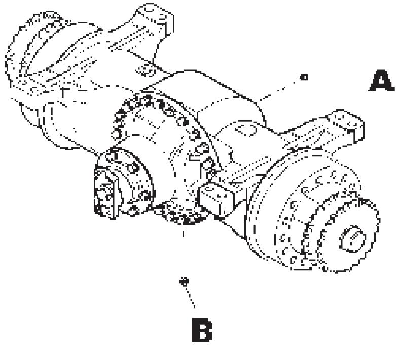
NOTE: The clearance will be correct when the fealer gauge is passed between the valve rod and the rocker, with a little resistance. 31- Rear axle housing compartment Park grader on a level area. Make sure the oil in the rear axle is near normal operating temperature. Remove drain plug (B), filler plug (A) to help oil drain more rapidly. After draining, re-install the drain plug and fill the housing to the level of the filler hole with the specified oil. Allow sufficient time for oil to fill all axle compartments. Wait 15 minutes and top off. Install and tighten filler plug.
EACH 2000 HOURS SERVICES
30- Hydraulic oil tank
WARNING
Fluid under pressure. Lower implements to ground, shut off engine and move control levers several times. Loosen filler cap to relieve pressure, before loose
Remove the drain plugs, and drain oil in a container.
Remove the filler cap to vent the tank as it drains.The filler element should be changed and the strainer cleaned at this time. Rear axle housing A- Filler and level plug B- Drain plug
32- Front wheel bearings Change the grease
Loosen fixing bolts and remove cover. Remove grease, clean bearing housing and fill each with 0.9 kg (2 lbs) of the specified grease (see Service and Lubrication Guide, starting on page 69). 34- Tandem drive cases Change oil Remove the drain plug (3) from each case and drain the oil. Remove the level (2) and filler (1) plugs from each case. Install the drain plugs. Add specified oil through the filler holes until oil runs out of the oil level hole. Install and tighten level plugs and filler plugs in each case.
Front wheels bearings
33- Rear axle housing end compartment Change oil Make certain oil in rear axle end compartment is near operating temperature. Remove drain plugs located on bottom of each end compartment and allow oil to drain. Clean drain plugs, re-install and tighten plugs securely. remove each oil level and filler plug and fill each compartment with the specified lubricant to level even with filler plug openings. Install and tighten oil level and filler plugs securely. Tandem drive case - Change oil
1- Filler plug 2- Level plug 3- Drain plug
PERIODIC SERVICES
35- Engine cooling system Drain and flush
WARNING
There is fluid under pressure inside. Follow the operator's Manual instructions to relieve the pressure before opening the radiator cap.
Turn the radiator cap slowly to relieve pressure. Open radiator drain cock located under the radiator (3) and the drain cock located on the oil cooler and let the water drain.
Rear axle housing A- Filler and level plug B- Drain plug
Check to see that all hoses are in good condition and that clamps are not damaged or loose. Replace if necessary. 36- Engine coolant radiator Clean
After draining, flush the radiator with clean water, with water that does not contain large amounts of calcium.
Fill the cooling system with a mixture of 50% of ethylene glycol and 50% of clean water to about 1-1/4" (30 mm) below the filler neck.
Install radiator cap. Start and run engine until coolant reaches normal operating temperature.
Stop engine. Check level of coolant and add if necessary.
NOTE: Ethylene glycol is an anti-freeze and coolant for cooling systems that guarantee's perfect heat exchange when mixed with clean water in 50/50 solution. Ethylene glycol contains special additivies that prevent the formation of rust, calcium deposits and foaming for the entire cooling system. Air flow when working
1- Air nozzle 2- Radiator tubes 3- Radiator fins 4- Debris
WARNING
Use an air compressor and a suitable nozzle to direct a stream of air over and through radiator core in the opposite direction of normal air flow to remove all dirt and debris.
Wear safety glasses with side shield or goggles when using compressed air for cleaning. This reduce the danger of accidents caused by flying particles. Limit the pressure to 207 kpa (30 PSI) according to local or national requirements.
NOTE: It may be necessary to spray the exterior of radiator core with water and detergent to remove caked dirt.
37- Air filter Clean
The outer element of the air cleaner should be disassembled only when the air restriction indicator is in the red area. For correct maintenance of the air filter proceed as following:
a)Clean dirt and oil from air cleaner assembly. b)Loosen clamp (2) attaching cup to air cleaner body.
Remove cup (7) and deflector (6). c)Remove outer element by loosening wing nut and gasket.
NOTE: Visually check inner element each time outer element is cleaned or replaced. d) The filter may be cleaned with compressed air.
WARNING
Wear safety glasses with side shield or goggles when using compressed air for cleaning. This reduces the danger of accidents caused by flying particles. Limit the pressure to 30 PSI (2 kg/cm2) according to local or national requirements.
If required clean fins inside air cleaner with a stiff fiber brush.
e)To clean element with compressed air, direct dry clean air up and down plates on clean air side of element until all dust is removed.
ATTENTION: The inner element of the air cleaner is extremely important and should never be disregarded. We suggest that it be changed after 3 outer elements have been changed.
1- Inner element; 2- Nut; 3- Capscrew; 4- Nut; 5- Clamp; 6- -'ring; 7- Cup; 8- Nut; 9- Filter housing 10- Outer element f)After the filter has been cleaned and dried, it must be inspected for ruptures or holes. Place a bright light inside the element and inspect it from the outside.
The light will shine through any holes or tears. If any holes are evident, install a new element.
g)Inspect inner element retaining wing nut (4). Change wing nut if it is damaged.
h)Clean inside of the air cleaner body and cup (7) before re-installing element (5). Insert element in air cleaner body and tighten wing nut.
i)Install cup (7) unloader valve at bottom and tighten clamp securely. Check to see that the clamp is correctly positioned. j)Check unloader valve lips (8). The lips must be free of debris. Dirt and mud can lodge in the lips and hold them open during operation. The valve lips must be open when the engine is at low idle or is stopped. The lips must point down to function. l)Check the air cleaner tube cap. If there is dirt, remove tube cap and blow dust from cap, remove debris if any is apparent. m) Start engine. Observe air cleaner restriction indicator with engine running at high idle. If restriction is indicated, air cleaner inner element must be replaced. As the inner element is not cleanable, always replace it after one year of service or if a restriction is still indicated after the outer element has been cleaned.
38- Parking brake Check Check parking brake hand lever. It should have a distinct over-center action.
Adjust the brake by turning the top of the handle, clockwise (with brake released) to obtain over-center action. If handle adjustment is all taken-up, loosen the handle all the way and adjust the lower linkage. Remove the clevis pin (1) and turn yoke(3) clockwise several turns so that by lifting up on the lever (2) the hole in the clevis pin lines-up with the hole in the lever. Install clevis pin and secure with cotter pin tighten jam nut and readjust handle.
Parking brake The tandem wheel nuts should be periodically checked for tightness. Torque nut to 57.2 daNm (55.3 kgm) (400 lbs.ft). Then turn to next slot and install cotter pin.
39- Tandem wheel nut Check
Tandem wheel nut
40- Tandem wheel lug nuts Check
The tandem wheel lug nuts should be periodically checked for tightness. Torque nuts to 40.7 - 47.6 daNm (41 - 48.4 kg.m) 300 - 350 ft.lbs
Tandem wheel lug nuts
41- Front wheel bearing Check grease Remove the indicated cover, loosening the four (4) fasteners and check the condition of the grease. If necessary change the grease.
42- Tire pressure Check
WARNING
Do not inflate the tires with flammable gases or with air from systems that use alcohol injectors. This could cause explosion and/ or accidents.
Check the pressure with a tire pressure gauge. The normal pressure is: 13.00 x 24 - 10 ply tires 2.8 kg/cm² (40 psi) 13.00 x 24 - 12 ply tires 2.8 kg/cm² (40 psi) 14.00 x 24 - 10 ply tires 2.8 kg/cm² (40 psi) 14.00 x 24 - 12 ply tires 2.8 kg/cm² (40 psi) 17.50 x 25 - 12 ply tires 2.8 kg/cm² (40 psi)
Tire filler valve Do not stand directly in front of tire while performing maintenance. Always stand to one side and extend arm to filler valve. Be sure tires are properly inflated to the manufacture's specified pressure. Inspect for damage periodically. Check tires only when machine is empty and tires are cool to avoid under inflation. Do not use reworked wheel parts. Improper welding, heating or brazing, weakens them and can cause failure. Always use an inflation cage, safety cables os chains when removing tire lock rings or inflating deflated tires. Always deflate tires before removing lock rings or objects from tread, according to local or national requirements. Never begin to inflate a tapered bead tire unless bead seat band is securely in place over the lock ring. Improper inflation is a large contributor to tire failures.Under inflation will cause damage to the cord body of the tire. The repeated excessive flexing of the sidewall area may eventctually cause a series of breaks and separation in the cord fabric. Over inflation must also be avoided. For maximum flotation in very soft footing, inflation may be decreased. If 24 hour operation does not permit checking inflation pressure on completely cooled tires, a correction factor can be determined by experiment. Check as many times as possible when "cold" and again after two hours of operation. The average difference must be added to the recommended pressure when checking the tires during constant operation. Continous operation of equipment buids up heat and accompanying higher pressure in the tire. These normal increases are allowed for in the design of the tires.
WARNING
Travel pressures are recommended to optimize the performance of the machine during long transfer trips on open roads with empty bucket. Before putting the machine back to work, it is imperative to re-inflate the tires to work pressure to avoid damaging the tire walls.
NOTE: Never exceed the maximum pressure stamped onto tire sidewalls.