G140
ELECTRICAL SYSTEM CARE TO BE TAKEN PRIOR TO PERFORMING ANY WELDING PROCEDURE ON THE MACHINE Disconnect the positive (+) and negative (-) cables from batteries prior to performing any welding service on the machine. Connect the welding equipment ground cable to a 0,6 m (2 feet) maximum distance from the area being welded. Do not connect the welding equipment ground cable to the module cooling plate or to the engine control module (ECM) itself. Welding work is not recommended on installed engine or components.
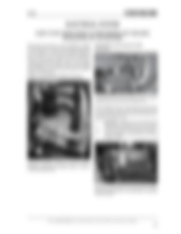
Transmission Control Module (TCM) Connectors
X23
Engine Control Module (ECM) Connectors
X24 B
TRANSMISSION CONTROL MODULE (TCM) X24 BLACK CONNECTOR AND X23 GRAY CONNECTOR
When welding service is necessary to be performed on the machine, make sure to disconnect the X24 connector and the X23 connector from the right handside of the operator’s cab.
!
A
CAUTION: If welding service is performed without disconnecting the X24 and X23 connectors shown in illustration, damages can be caused to the transmission control module (TCM).
C
ENGINE CONTROL MODULE (ECM) DETAILS, SHOWING LOCATION OF CONNECTORS A, B, AND C TO BE DISCONNECTED
POSITION OF THE ENGINE CONTROL MODULE (ECM), ON LEFT HAND-SIDE OF THE MACHINE, IN ENGINE COMPARTMENT.
Read the SAFETY RULES on the preceding pages for machine protection and the safety of employees
123


