12 minute read
INSTRUMENT PANEL INDICATORS


INSTRUMENTS/CONTROLS
4.The following LED’s indicators do not activate the audible warning: • Parking brake, D; • Steering secondary (optional), P; • Differential lock, T; • General warning light, L; • High beam, N; • Turn signals, O and M. 5.Differential lock functions only with the parking brake disengaged and only in 1st to 7th gears. 6.Q - Speedometer registers the travel speed.
R - Indicates the engine RPM during operation.
S - Not available.
INSTRUMENT PANEL INDICATORS
A. ENGINE WATER TEMPERATURE
When the light is ON, it means that the engine coolant has overheated which could be caused by: • Lack of coolant in the system • Radiator cooling fins clogged • Radiator circuit clogged • Fan hydraulic drive system malfunction • Defective thermostat.
B. HYDRAULIC OIL TEMPERATURE
When the light is ON, it means that the oil is overheated which could be caused by: • Use of oil with improper viscosity • Low oil level.
C. TRANSMISSION OIL TEMPERATURE
When the light is ON, it means that the oil is overheated and its probable causes are: • Suction line filter clogged • Low oil level • High oil level • Transmission hydraulic oil circuit troubles.
D. PARKING BRAKE
When the light is ON, it means that the brake is actuated.
E. LOW BATTERY CHARGE
When this light is ON, with the engine running, indicates defects in the charging system, caused by: • Defective alternator • Charging resistor damaged
F. LOW TRANSMISSION OIL PRESSURE
When the light is ON, this indicates insufficient oil pressure that may be caused by: • Use of oil with improper viscosity • Low transmission oil level • Defective switch and/or defective panel.
G. LOW ENGINE OIL PRESSURE
When the light is ON, this indicates insufficient oil pressure that may be caused by: • Use of oil with improper viscosity • Low engine oil level • Engine oil leak • Defective pressure switch
INSTRUMENTS/CONTROLS
H. LOW BRAKE OIL PRESSURE
When the light is ON, this indicates insufficient oil pressure that may be caused by: • Pump abnormalities • Air in the brake system • Oil leak on brake lines • Defective pressure switch.
I. AIR FILTER RESTRICTION
When the indicator remains on constantly, the air filter element is clogged and it will be necessary to clean or replaceit. • Defective switch and/or defective panel.
J. HYDRAULIC OIL FILTER RESTRICTION
When the indicator remains on constantly, the oil filter element is clogged and it will be necessary to replaceit.
K. TRANSMISSION OIL FILTER RESTRICTION
When the indicator remains on constantly, the oil filter element is clogged and it will be necessary to replaceit.
L. WARNING FLASHER
This indicator flashes when the button located on the right console is pressed in.
M. RIGHT TURN SIGNAL N. HIGH BEAM O. LEFT TURN SIGNAL P. SECONDARY STEERING LIGHT (OPTIONAL)
Not available.
4. DIFFERENTIAL LOCK SWITCH OPTIONAL
This switch is used to lock or unlock the differential when it is necessary. Use the differential lock switch only in straight line operation. To steer or articulate the machine the operator must turn off the differential lock switch.
IMPORTANT: Do not turn off the differential lock system when the motorgrader is operating.
5. GEAR AND ERROR CODE DISPLAY
This display shows the actual neutral, forward or reverse transmission gear selected. When an error occurs the display will flash an error code indicating that a problem has been detected in the system. When the ignition key is first turned on, the display will show three sets of double letters (TD DC ER) at the top and three 8’s. The first 8 will have a diagonal line through it. This is a system light check. If the key is left in this position without starting the engine, the display will next flash ER100 few times. This designates the revision version of the transmission’s computer software. There is also an error code ER100 but this error code only appears during recalibration. The revision code may change. The next code will be ER101, ER102, etc.
6. STEERING WHEEL TILT LEVER
Loosen the lever and adjust the steering wheel position to obtain more comfortable operating position. Tighten lever again to assure the steering wheel does not move.
7. HOURMETER
The hourmeter indicates operating hours with the engine off and key switch in the RUN position.
INSTRUMENTS/CONTROLS
8. “INCHING” PEDAL
The “inching control pedal” is helpful under the following conditions: • When starting or stopping • For motorgrader finishing work requiring “creeper gear” or very slow speeds • For very slow ground speed work to increase engine speed for hydraulic performance (this should rarely be necessary because of the wide range performance of the hydraulic system). CAUTION: Do not abruptly depress and release inching pedal to start a heavy load or free a stuck machine.
9. CONSOLE TILT PEDAL
The console may be adjusted to improve operator comfort. Push the pedal to free the console. Position the console in the desired position and then release the pedal to lock the console again.
10. BRAKE PEDAL
This pedal actuates the service brakes. To stop the motorgrader press down on brake pedal. NOTE: Do not descend steep slope using only the service brake. Reduce the speed and apply the brakes. Select an appropriate speed, allowing total machine control. This will avoid brake heating, and will increase the life of the components.
11. ACCELERATOR/DECELERATOR PEDAL
The accelerator/decelerator pedal is connected to the engine throttle controls. To accelerate the engine, press down on the front part of the pedal and to decelerate press down on the rear of the pedal. When the pedal is released, the engine speed will return to the hand throttle setting.
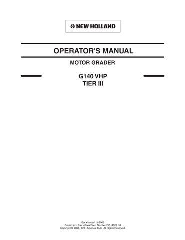
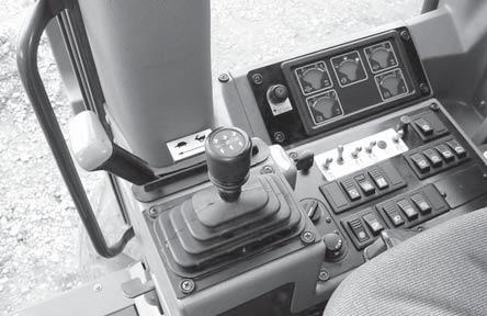
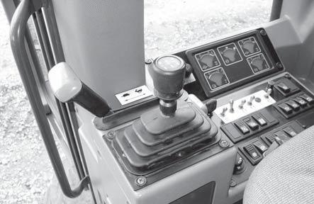
GROUP 3
Dashboard, transmission control lever, throttle control lever, fuse box and master switch.
2
3 6 5
7
1 8 4
1. FUSE BOX 2. THROTTLE CONTROL LEVER 3. TRANSMISSION CONTROL LEVER 4. TOGGLE/ROCKER SWITCH PANEL 5. GAUGE PANEL 6. IGNITION SWITCH 7. MASTER SWITCH 8. POWER TAKE OFF
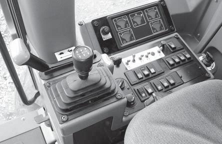
1. FUSE BOX
In the fuse box are installed all the motorgrader fuses. For the identification of the fuses, refer to the electrical diagram.
INSTRUMENTS/CONTROLS
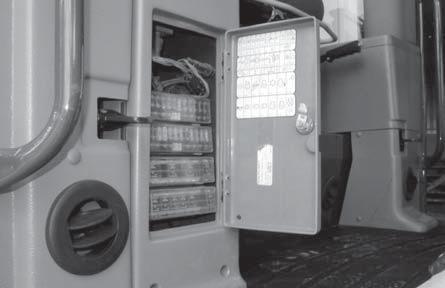
2. THROTTLE CONTROL LEVER
2
The engine will remain at low idle with the throttle control lever all the way forward and engine speed will increase as the lever is pulled back.
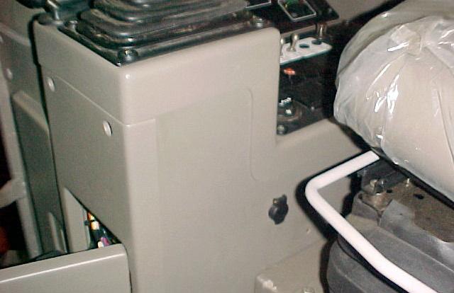
3. TRANSMISSION CONTROL LEVER
SHIFT PATTERN:
R • Reverse F • Forward N • Neutral DS • Down shift US • Up shift The transmission control lever is used to select the desired forward or rearward speeds. These machines are equipped with a 8 speed forward and 4 speed reverse transmission. The gear speed change is done using a shift lever. Toobtain forward speeds place this lever to the front. Toobtain reverse speeds place this lever to the rear. By using this lever the proper speed (1st, 2nd, etc.) can be selected. Observe the gear display readout for confirmation of the gear selected. If the display shows an “error code” it means that some fault has occurred in the transmission system. Therefore it is necessary to contact a NEW HOLLAND dealer. When the machine is stopped, any gear lower than F3 or R2 may be selected to start again. A single speed change is done with a single push and release of shift lever. If the shift control lever is pushed and held to the right or left the gear speeds will change automatically.
NEUTRAL LOCK
3
LOCK RING
Tomove the shift lever out of neutral position, release the “Neutral Lock” by raising the release ring located under the shift handle knob.
INSTRUMENTS/CONTROLS
4. TOGGLE SWITCH PANEL
1 62 3 4 5 18
8 7 9 10 11 12
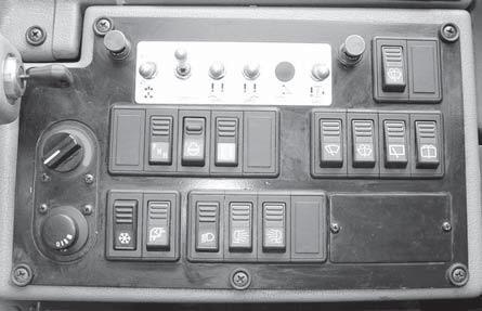
13 14 15 16 17
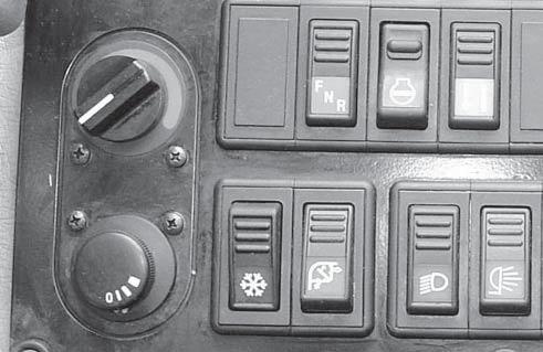
1. SADDLE LOCK PIN SWITCH The saddle lock pin switch activates a solenoid valve which sends hydraulic fluid for cylinder rod movements to release and engage the saddle pins. With the toggle switch pushed away from the operator’s seat, the pins remain retracted from the saddle and with the toggle switch pushed towards the operator’s seat, the pins will extend and engage the locator hole in the saddle. Use the blade lift cylinders to assist movement of the saddle lock pins. 2.RIPPER / SCARIFIER SWITCH The ripper / scarifier switch activates a solenoid valve which sends hydraulic fluid to the rear ripper or the front scarifier cylinders. Tomove the rear ripper, push the toggle switch away from the operator’s seat. To move the front scarifier, push the toggle switch towards the operator’s seat. 3.MOLDBOARD FLOAT SWITCH - LEFT SIDE This switch activates or deactivates the moldboard float function for the left side of the blade. To activate the float function, push the toggle switch away from the operator’s seat. To deactivate the float function, push the toggle switch towards the operator’s seat. 4.MOLDBOARD FLOAT SWITCH - RIGHT SIDE This switch activates or deactivates the moldboard float function for the Right side of the blade. To activate the float function, push the toggle switch away from the operator’s seat. To deactivate the float function, push the toggle switch towards the operator’s seat. 5.FRONT BLADE FLOAT SWITCH This switch activates or deactivates the front blade float function. To activate the float function, push the toggle switch away from the operator’s seat. To deactivate the float function, push the toggle switch towards the operator’s seat. 6.MOLDBOARD ANTISHOCK FUNCTION
SWITCH This switch activates and deactivates the moldboard cylinders antishock function. To activate the antishock function, push the toggle switch away from the operator’s seat. To deactivate the antishock function, push the toggle switch towards the operator’s seat. 7.ENGINE LOGIC SWITCHES These switches are used to check the logic of operation of the engine. 8.COME-HOME SWITCH This switch is used to move the machine in the event of a transmission electronic control unit problem. The rocker switch has three positions: Forward, Neutral and Reverse. The switch must be in the Neutral position with the park brake applied to start the machine, when the come-home mode is activated. The transmission shifter and the inching pedal are bypassed when in the come-home mode. See the Maintenance Section for more details on how to activate the come-home mode. 9.FRONT WINDSHIELD WIPER SWITCH This switch is used to activate the front windshield wiper. The rocker switch has three positions: OFF, Low and High.
INSTRUMENTS/CONTROLS
10.FRONT WINDSHIELD WASHER SWITCH This switch is used to activate the front windshield washer. 11.REAR WINDOW WIPER SWITCH This switch is used to activate the rear window wiper. The rocker switch has three positions: OFF, Low and High. 12.REAR WINDOW WASHER SWITCH This switch is used to activate the rear window washer. 13.AIR CONDITIONER SWITCH This switch activates the cab air conditioner. Toturn the air conditioner on, push on the symbol side of the rocker switch. 14.CAB AIR RECIRCULATION SWITCH This switch closes the cab recirculation door to prevent outside air from coming into the cab. Toclose the recirculation door to recirculate the cab air, push on the symbol side of the rocker switch. 15.WORK LIGHTS SWITCH This switch activates the work lights above the moldboard and below the cab. The work lights switch is a three-position switch. The first position turns the lights OFF. Toturn on the lights above the moldboard, push the symbol side of the rocker switch to the second position. Toturn on the lights under the cab, push the symbol side of the rocker switch to the third position. The lights above the moldboard will stay on with the switch in the third position. 16.REAR FLOODLIGHT SWITCH This switch activates the rear floodlights. Toturn on the rear floodlights, push the symbol side of the rocker switch. 17.FRONT FLOODLIGHT SWITCH This switch activates the front floodlights. Toturn on the front floodlights, push the symbol side of the rocker switch. 18.LOWER FRONT WINDSHIELD WIPERS SWITCH This switch is used to activate the lower front windshield wipers. 1.CAB HEAT CONTROL Toincrease the temperature in the cab, turn the cab temperature control knob clockwise. To decrease the temperature in the cab, turn the cab temperature control knob counterclockwise. 2.BLOWER FAN SPEED SWITCH Toincrease the cab blower fan speed, turn the cab blower fan control counterclockwise until the desired fan speed is obtained. The blower fan speed switch has four positions: 0.OFF
I.Low
II.Medium
III.High 1
2
5. GAUGE PANEL
A.ENGINE OIL PRESSURE GAUGE The engine oil gauge indicates the pressure at which the engine oil is circulating through the engine. The red area means insufficient pressure. The green area means normal operating pressure, and the yellow area, excessive engine oil pressure.
INSTRUMENTS/CONTROLS
B.ENGINE COOLANT TEMPERATURE GAUGE • The marker in the GREEN area indicates the normal operating temperature range 80° to 95°C (176° - 203°F) • The WHITE area indicates low temperature. • The RED area indicates high temperature. If during the work cycle, the coolant temperature stays either in the WHITE or RED area, stop the engine to check the cause of the problem. C.FUEL LEVEL INDICATOR GAUGE The green area indicates the normal operating level. Refill the tank using filtered fuel as recommended. Refill the tank at the end of each work day, to avoid water condensation. Never let the fuel tank run-dry, this will cause air to enter the fuel system. Never refill the fuel tank with the engine running. D.TRANSMISSION OIL PRESSURE GAUGE The marker of the transmission oil pressure gauge must stay within the green area which indicates normal operating pressure. If the marker enters the red area, it is a signal that the oil pressure is too low. Do not operate the machine with low transmission oil pressure. Stop and check the cause of the problem. E.TRANSMISSION OIL TEMPERATURE GAUGE The marker must register in the green area. Do not operate the machine when the gauge is in the red area. Stop the machine and determine the cause of high temperature.
6. MASTER SWITCH
The machine electrical functions can only be actuated if the rotary master switch is activated. The master switch is activated by the starting switch in the “ON” position.
7. AUXILIARY ELECTRICAL CURRENT RECEPTACLE
The machine is equipped with a 24V auxiliary electrical power supply.
8. IGNITION SWITCH
This switch is a rotary type and is activated with a key.
ACC OFF
RUN
START
It has four positions:
ACC - Acessories
In this position some circuits such as the wipers and lights, are energized for use.
OFF
In this position all key activated electrical circuits are off. The key can be removed.
RUN
In this position all key activated electrical circuits are “ON”.
START
In this position, the starting circuits are energized. The switch is spring controlled for start and will return to the “RUN” position when the key is released. CAUTION: Never leave the key in the “ON” position when the engine is not running.