4 minute read
DIESEL FUEL SYSTEM


LUBRICATION/FILTERS/FLUIDS
DIESEL FUEL SYSTEM
Service Specifications
Fuel Tank Capacity.............................................................................................341 liters (90 U.S. Gallons) Interval for draining water from the fuel filter...............................................................50 hours of operation Fuel filter replacement interval..................................................................................500 hours of operation or once each year, whichever occurs first Adjust fuel injector...................................................................................................1000 hours of operation or once each year, whichever occurs first Clean and calibrate fuel injectors and fuel pump................................................1000 hours of operation or every 6 months, whichever occurs first.
Fuel Conditioner
Diesel fuel conditioner is available from your dealer. Follow the instructions on the can. The conditioner will: 1. Clean the fuel injectors, valves and manifold for increased service life. 2. Disperse insoluble gummy deposits that can form in the fuel system. 3. Separate moisture from the fuel. 4. Stabilize the fuel in storage.
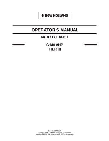
Fuel Filler Cap
LUBRICATION/FILTERS/FLUIDS
Diesel Fuel
Use No. 2 Diesel fuel in the engine of this machine. The use of other fuels can cause the loss of engine power and high fuel consumption. In very cold temperatures, a mixture of No. 1 and No. 2 Diesel fuels is temporarily permitted. See the following note. NOTE: See your fuel dealer for winter fuel requirements in your area. If the temperature of the fuel lowers below the cloud point (wax appearance point), wax crystals in the fuel will cause the engine to lose power or not to start. The Diesel fuel used in this machine must meet the specifications in the chart below or Specification D975-81 of the American Society for Testing and Materials.
Fuel Storage
If you keep fuel in storage for a period of time, you can get foreign material or water in the fuel storage tank. Many engine problems are caused by water in the fuel. Keep the fuel storage tank outside and keep the fuel as cool as possible. Remove water from the storage container at regular periods of time. Fill the fuel tank at the end of the daily operating period to prevent condensation in the fuel tank.
Specifications for Acceptable No. 2 Diesel Fuel
API gravity, minimum................................................................................................................................34 Flash point, minimum...............................................................................................................140°F (60°C) Cloud point (wax appearance point), maximum..............................................-5°F (-20°C) See Note above Pour point, maximum................................................................................... -15°F (-26°C) See Note above Distillation temperature, 90% point................................................................. 540 to 640°F (282 to 338°C) Viscosity, at 100°F (38°C) - Centistokes....................................................................................... 2.0 to 4.3 Saybolt Seconds Universal............................................................................................................. 32 to 40 Cetane number, minimum..............................................................43 (45 to 55 for winter or high altitudes) Water and sediment, by volume, maximum........................................................................................0,05%
WARNING: Engine fuel is flammable and can cause a fire or an explosion. Do not fill the fuel tank or service the fuel system near an open flame, welding, burning cigars, cigarettes, etc. Never refuel the machine when the engine is hot or running. Never smoke while refueling.
LUBRICATION/FILTERS/FLUIDS
Fuel Tank Drain Cock Clean
Open the drain cock, before engine start and allow water or sediment to drain. Close the drain cock when fuel runs out.
WARNING: Extinguish all smoking materials or open flames before opening the sediment drain due to presence of flammable fluids.
Fuel System Air Bleed
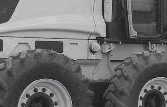
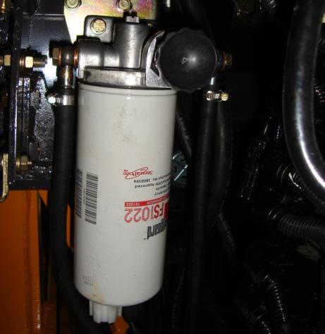
1. Clean the area around the water separator filter head to avoid contamination. 2. Completely loose the aluminum bleeder screw (3) located on the filter head, with a screw driver. 3. Be sure that the water drain bolt (4) on the lower part of the filter is completely tight. 4. Manually loose 3 to 4 turns the filter pumping knob (5). 5. Prime the knob until the Diesel fuel comes out through the bleeder screw (3) hole without the presence of bobbles. 6. Manually tight the knob (5) and the bleeding bolt(3).
3
5
Fuel Filters
These are lock ring type cartridge filters. Clean the area around the fuel filter (1) and fuel water separator filter (2) to avoid contamination.
2 1 4
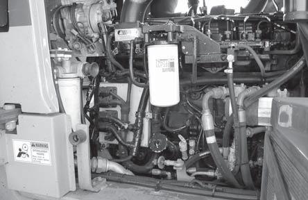
3. BLEEDER SCREW 4. DRAIN BOLT 5. PUMPING KNOB
1. FUEL FILTER 2. WATER SEPARATOR FILTER
Remove the filters and clean carefully the area around the filter head gasket. Change the fuel filters and sealing rings. Fill the filters with clean fuel and lubricate the sealing rings with new engine oil. Assemble the filters and tight them manually. After the assembly, make the fuel system air bleed procedure.
LUBRICATION/FILTERS/FLUIDS
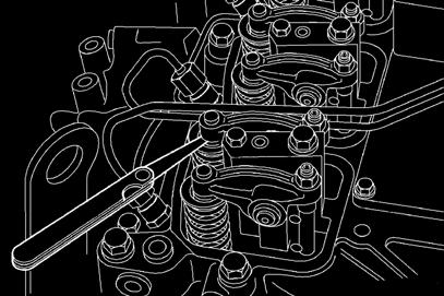
Valve Clearance Adjustment
EACH 1000 HOURS
Always adjust the valve clearance with engine cold, that is, with engine coolant temperature below 140ºF (60°C). First determine the top dead center (TDC) on engine nº 1 cylinder. To perform so, rotate the crankshaft slowly, using the adapter and gear of the manual rotating tool. Install the synchronizing pin and adjust the following valves: 1A, 1E, 2A, 3E, 4A, 5E. Remove the synchronizing pin, rotate the crankshaft 360° and install again the synchronizing pin. Perform the adjustment of the following valves: 2E, 3A, 4E, 5A, 6A, 6E. Clearance of valves must meet the specifications of table below:
Valves min. max. rated
Intake 0,152 mm 0,381 mm 0,254 mm Exhaust 0,381 mm 0,762 mm 0,508 mm
NOTES: Clearance will be correct if a slight effort is felt when the feeler gauge is introduced between the valve stem and the rocker arm. Tighten the lock nut to 24Nm (212 lb.in) torque.