18 minute read
Malfunctions


Fuses and relays
F12_3 25A fuse / working light
F12_4 25A fuse / working light
F12_5 25A fuse / working light
F12_6 25A fuse / working light
F20_1 100A fuse / supply cabin Kl15
F20_2 100A fuse / supply E1005 Kl15
F20_3 100A fuse / charging current
F20_4 100A fuse / Kl30 floodlight
F20_5 100A fuse / Kl30 counterweight floodlight
F20_6 100A fuse / engine
F137 8A fuse / Reserve
F138 100A fuse / Service circuit supply
F139 100A fuse / Engine control system
F140 15A fuse radio box
F141 15A fuse cigar lighter
F142 15A fuse service socket
F143 25A fuse service lighting
F144 15A fuse ladder control system
F145 Reserve
F152 25A fuse / Quantum
F20_7 8A fuse / E1003F164 7,5A fuse / E1003
F37 25A fuse / Ether
F119 8A fuse / Kl30
F120 50A fuse / air conditioning
F166 Reserve
F167 25A fuse / Foot heating option
F169 15A fuse / Charging
F121 50A fuse / air conditioning F170 Reserve
F122 15A fuse / optional windshield wiper
4.3.2Cabin connection box E1005
AllotherfusesandrelaysareonthecabinconnectionboxE1005.Thecabinconnection box E1005
Danger copyright © Liebherr-Mining Equipment Colmar SAS 2021
Incorrect or bypassed fuses do not offer the machine's operator or the electrical system the required degree of protection. Only use original fuses. Never bypass electrical fuses.
If required, order replacement fuses from Liebherr.
A1008_1 Relay platine E1005
A1014 Platine current regulation
A1019 Regelation plate
A1020 FSG Plate
5.1Servicing the machine safely
General safety instructions
nel.
givenintheoperatinginstructionsforrepeattests/inspections.Itisimperativethatasuitablyequippedworkshopisavailable in order to carry out maintenance work.
venattheendoftheseoperatinginstructions defines precisely who is required / permitted to carry out what work. Jobs listed as daily / weekly work may be carried out by the machine's driver or maintenance personnel when they have received appropriate instruction. The remaining work may only be carried out by specialist personnel with appropriate training.
the manufacturer. Original replacement parts are always guaranteed to meet these criteria.
rrying out maintenance work. Avoid the wearing of rings, wrist watches, ties, scarves, open jackets, baggy clothing etc... There is a risk of injury from, for example, getting caught up or being drawn in. Protectivegoggles,safetyhelmets, safety shoes andgloves, reflectivevestsand ear protection etc. are required for specific jobs.
diesel engine while the diesel engine is running.
Personswithpacemakersshouldnotapproachwithin20cmoftherunningdiesel engine.
Do not touch voltage-carrying parts on the electrical connection of the individual solenoid injection pumps (Unit Pumps UP) while the diesel engine is running. nance work.
pair work. Designate persons in charge of supervision.
maintenance work on the machine on level, firm ground with the working equipment set aside and the engine switched off.
every maintenance locations on the uppercarriage, is when the uppercarriage is aligned with the undercarriage so that the sprockets locate at the back-end. The ladder situated on the undercarriage only corresponds with the uppercar- onsduringmaintenanceandrepairwork. ents, of the hydraulic hoses and of the counterweight must be replaced after every removal. work, they must be immediately reinstalled and checked at the end of the work. ularly when working under the machine, earlyvisiblepositiononthecontrolpanel. Pull out the start key and shut off the main battery switch. ated heaters only in well ventilated areas. Before operating these units, check ventilation. applicable local regulations.
Cleaning
hemachinebeforestartingmaintenanceorrepair work and pay particular attention to connections and screw fittings. Do not use aggressive cleaning products and use lint-free cleaning cloths.
chine for the first two months after initial set-up of the machine (or after repainting).
other cleaning materials: onsandtherimbearingtopreventwater or steam entering the bearing points. or steam may not be permitted to enter. Electric motors, electrical components,control boxes,plugconnections and air filters are particularly at risk. into contact with hot cleaning products during cleaning work. The fire extinguisher could start. observe following recommendations: er than 20 inches neutral cleaning agents such as customary car shampoos diluted to 2 or 3 percent maximum chafing and damage. onsandtherimbearingtodisplaceany water or cleaning products that may have entered.
Corrosion protection
ne must be inspected and renewed at regular intervals. For further information, refer to the Maintenance manual for corrosion protection.
Field of view
evitablyreinstalledandcorrectlyadjustedbeforetheinitialset-upofthemachine.
correctly adjusted.
ing operation or when travelling.
hange on the machine, the sight conditions must be maintained. These conditions must otherwise be checked according to ISO 5006. must always be clean.
e dangers due to a restricted field of view are minimized, particularly for machines with an operating weight which is superior to 40 tons.
Crack testing
fully, there is a possibility of individual cases of overloading occurring, which could lead to cracks or loose connections. Themachineshouldthereforebecheckedregularlyforcracks,looseconnections or other visible damage to maintain operational safety.
isessentialthatthemachineiskeptclean and cleaned regularly.
nance plan: supported, on firm, horizontal substrate, with the equipment in longitudinal and cross direction for variable loads. Current accident prevention regulations must be adhered to. axle andgearbox storage, support outriger, lower slewing ring support with tower and slewing ring. perslewingringsupport,cabsuspension,mountingforslewing gear andcounter weight. ttachments, e.g. boom, stick, quick change adapter, digging tool and grapple. ns and pinconnections, ascents, ladders and mounting elements. ally.Ifacrackissuspected,thedyepenetration test should be carried out as a crack test on areas which do not have goodvisibility,suchastheringbearingsupport,inordertoincreasetestingsafety. diately. Welding work on load-bearing parts of the earth-moving machinery, loading devices and transport devices may onlybecarriedoutbytrainedspecialistpersonnelandonlyinaccordancewiththe accepted rules of welding engineering. In case of doubt, contact the LIEBHERR customer support service to discuss suitable remedies.
Welding, drilling, firing and grinding work
undercarriage, uppercarriage, equipment this rule is neglected, the warranty is voided. d grinding work on the machine with expressauthorization.Cleandustandcombustiblematerialsoffthemachineandits surrounding areas before welding, drilling, firing or grinding. Ensure adequate ventilation. Risk of fire or explosion. move the negative terminal first and reconnect it last. pairshouldbedoneoncomponentswhichmaycontain inflammable gases (welded counterweight, components must be previously andsufficiently ventilated with pressurized air to avoid all fire or explosion hazard point, so the welding current will not run through parts like the swing ring, rotary connection, gears, bushings, bearings, hinges, joints, hydraulic hoses, sockets, rubber parts or seals.
Process materials
chemicalsubstances,observetheappropriate current safety regulations for the product.
ement parts are disposed of in a safe and environmentally acceptable manner.
(Risk of burning and scalding).
Repair work
parts.Usedeviceswhicharesuitablefor thispurpose and which have sufficient load capacity. When replacing single parts and larger subassemblies, carefully secure them on lifting devices so that they do not presentarisk.Onlyusesuitableandcorrectlyfunctioningliftingdevicesandloadtakeup devices with adequate load capacity. Do not stand or work under swinging loads.
rying capacity.
Wear work gloves when working with wire cables. him. forms which are appropriate for the job. Donotusemachinepartsasclimbingdevicesiftheyarenotdesignedforthispurpose.
When working at height, wear a harness to prevent falling.
Forfurther information, seesection"Maintenanceanchorpoints"or contactLiebherr customer service.
rmsandladders arefree ofdirt,snow and ice.
carefully, so that pneumatic cylinders do not hit their stops, because this could cause mechanical damages.
operate is securely supported before working (e.g. replacing teeth). Prevent metal touching metal when doing this.
ly totally released the pretension of the chain tensioning unit. securely supported with appropriate supports.
jeopardize stability and prevent metal touching metal while doing this. trained specialist personnel.
connect the upper structure to the chassis using stop bolts.
ment.
pressure can penetrate the skin.
ment, switched off the engine and depressurized the hydraulic system. After switching off the engine, with the start key in contact position and with the safety lever downinto its lowestposition,youmustoperateallpilotcontroldevices(joystick and pedals) in all directions in order to reduce the actuating and dynamic pressures in the work circuits. You must then reduce the internal tank pressure asdescribed in these operating instructions.
Electrical system
Have all faults, such as loose connections, blown fuses and lamps and clogged or abraded cables rectified by personnel.
the event of malfunctions in the power supply.
pment may only be carried out by skilled electrical personnel or by trained personnel under the supervision of an electrician in accordance with electrical regulations.
second person is available to operate the emergency-off or the main switch and overvoltage release. Cordon off the working area with a red and white safety chain and a warning sign. Only use insulated tools.
voltage, briefly disconnect the supply cable at earth and electronic devices such as capacitors using an earthing rod.
that they areoff circuit, earth them and then disconnect them briefly. Insulate adjacent live parts.
electric arc welding on the machine. Firstdisconnectthenegative,thenthepositivepole.Whenreconnecting,proceed in the reverse order.
Hydraulic accumulator
personnel.
licaccumulatorscancauseseriousaccidents.
hydraulic system (hydraulic system including hydraulic tank), as described in these operating instructions.
accumulator.
The hydraulic accumulator can be damaged by heat penetration and can be made to rupture by mechanical working. RISK OF EXPLOSION!
SION if oxygen or air is used.
purpose of use before installation.
on hydraulic accumulators. Ensure that this marking remains visible.
Hydraulic lines and hoses
work on hydraulic lines and hoses!
ibledamageandanypossibledamagemustbeimmediatelycheckedforleakage. else.
and burns.
natural aging process. This restricts their duration of use. common causes of failure.
ing to lines and hoses at place of use must be adhered to. temperatures, frequent movement cycles, extremely high pulse frequencies, multiple shift usage).
the following arefound during inspection: cture formation in hose material); whether ina unpressurized orpressurized state or on bends e.g. sheath separation, blistering; ings which reduce the tightness of the fittings or thehose / fitting connection; tly. Do not mix up the connections. pressure hoses, the screws from the half-clamps or full flange must always be attached to both hose ends and should only be tightened afterwards. ssure lines and hoses with bent fittings, thesidewiththebentfittingmustalwaysbetightenedfirstandthenthesidewith the straight fitting tightened afterwards. attached and tightened subsequently. covers and protective devices are properly fastened. Doing this will prevent vibration and damage during operation. hoses or parts. prox.halftheexteriordiameterofthe hose is recommended. The distance should not, however, be less than 10 to 15mm. stick), check before initial start-up that there are no chafing areas in the entire area of movement.
Disposal
Disposal of the machine of the machine are disposed of correctly after the service life in accordance with all applicable national, regional or local regulations for waste disposal and environmental protection. uidsfromallcomponentsbeforedisposal.
Disposal of gas tanks and pressurized tanks ds disposed of in an applicable recycling point. technician. ts andoperating fluids manufacturer for disposal. of in an applicable recycling point.
Disposal of fuel, lubricants, operating fluids and consumables peratingfluids inapplicablecontainers before disposal.
5.2Maintenance access doors
5.2.1Overview of access doors
The machine has 5 access doors for maintenance. The locks integrated in the han- dles must be unlocked before starting to drive.
Caution!
Access doors cancloseaccidentally andtraptheoperatoror maintenancepersonnel.
When you have opened the access doors, latch them using the retainer.
Motor room
Cab elevation and hydraulictank installation


Oil cooler (for on-board oil cooling system)
Control valve
1Hydraulic tank
5.3Maintenance anchor points
You must always access to the machine through the access provided. Forinstallation,maintenanceandrepairwork,itispossiblethattheservicepersonnel is obliged to removefall protectionelementssuchas handrails toget access toor to remove some parts of the machine.
Danger!
Risk of falling when fallprotection elements are removed.
The machine has anchor pointsfor safe installation, maintenance and repair work.
Evenifappropriatefall-arrestequipmentisinstalledtotheanchorpoints,fall-arrest equipmentcannotpreventfalls.Commonsenseandfall hazardawarenessareimportant safety precautions for work that is done from above the ground.
5.3.1Approved anchor points
There are four types of approved anchor points on the machine:
The welded and the drilled anchor points have a specific label (see § "Signs on the machine"). To be easily identified, the welded and the drilled anchor points are also painted in blue (in white if the excavator is blue).
The lifting points given in the section "Transport drawings" can also be used as anchor points.
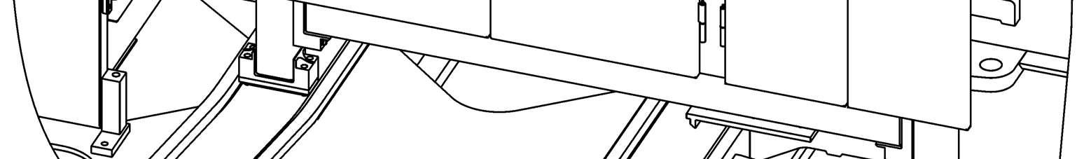
Thehorizontalmiddlebaronhandrailscanalsobeusedasanchorpoint(asillustrated below). The used handrail must have at least two vertical posts.
Welded anchor points
Drilled anchor points
5.3.2Use the anchor points
Before you use an anchor point, always do a check of its condition. If an anchor point has been used to arrest a fall, orif you are not sure about its safecondition,donotusethisanchorpointuntilithasbeeninspectedand,ifnecessary, tested by a competent person.
Always use the anchor points with applicable fall-arrest equipment. Use a harness with a maximum arrest force of 6kN. Only attach to approved anchor points.
Never attach more than three persons to a lifeline.
Never attach more than one person to another type of approved anchor point. If several persons must attachthemselves to the machine,they must usedifferent anchorpoints.
Never use an anchor point to attach parts or material.
Persons who must work with fall-arrest equipment must be specially trained. Alltheanchorpointsandthetighteningofthehandrailsmountingscrewsmustbe examinedbyauthorizedspecialistpersonnel.Formaintenanceintervals,referto the control and maintenance chart.
5.4Lubricants and operating fluids
5.4.1General information on changing lubricants and operating fluids
Note
Thequantitiesgiveninthelubricationandoperatingmaterialchartandonthelubrication chart in the cab are only guide values.
After each oil change or refill, check the level in the relevant unit.
Note!
Adheringtoregulationsforlubrication,levelchecksandoperatingmaterialchanges guarantees a high degree of reliability and a long service life for the machine. Itisparticularlyimportanttoadheretotheoilchangeintervalsandusethespecified type of lubricant.
Observe the followingwhenusing andcheckinglubricants and operating fluids:
All lubricants and operating materials are not miscible or compatible.
When you change the lubricant or the operating material for a component or a system,makesurethattheoldandthenewlubricantsoroperatingmaterialsare miscible and compatible with each other.
If not, flush the component or the system first with new approved lubricant or new approved operating material.
Note!
Cleanliness is of the utmost importance when changing oil.
Clean all filler plugs, filler covers and drainplugs andtheirsurroundings before opening.
For preference, drain off oil when it is at operating temperature.
Ensurethat oldoils arecollectedanddisposed of in anenvironmentallyacceptable manner using the removable oil filter cartridges.
Danger!
When checking and changing lubrication and operating materials, ensure that the following precautions are adhered to:
Unless otherwise indicated, carry out all work on the machine on level, solid ground and with the electric motor switched off.
Whenever you reach into the electric motor compartment, always secure the cover and side doors against accidentally falling back or closing.
Do not smoke and avoid naked flame.
Turn the main battery switch to position 0 (off) and remove the ignition key.
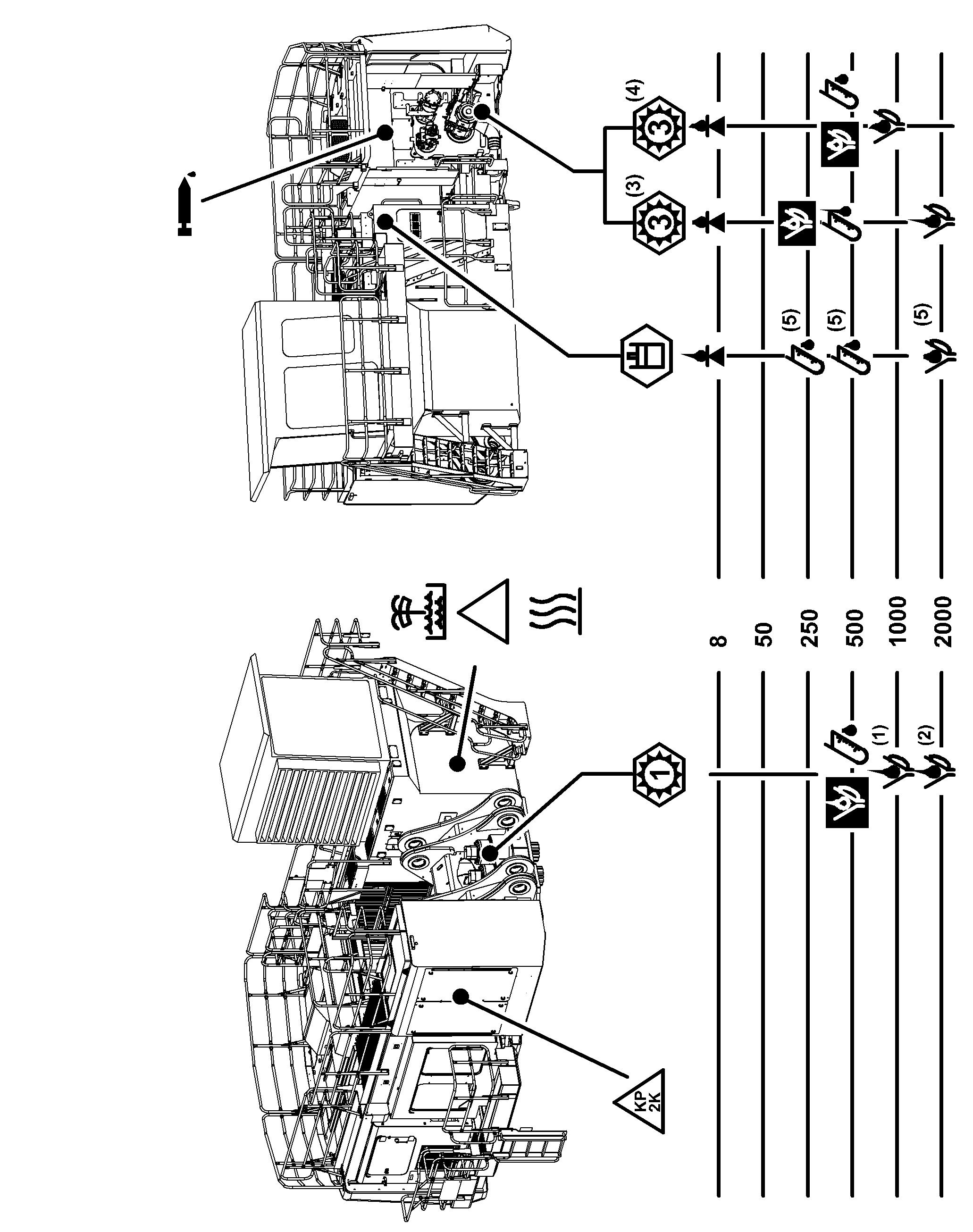
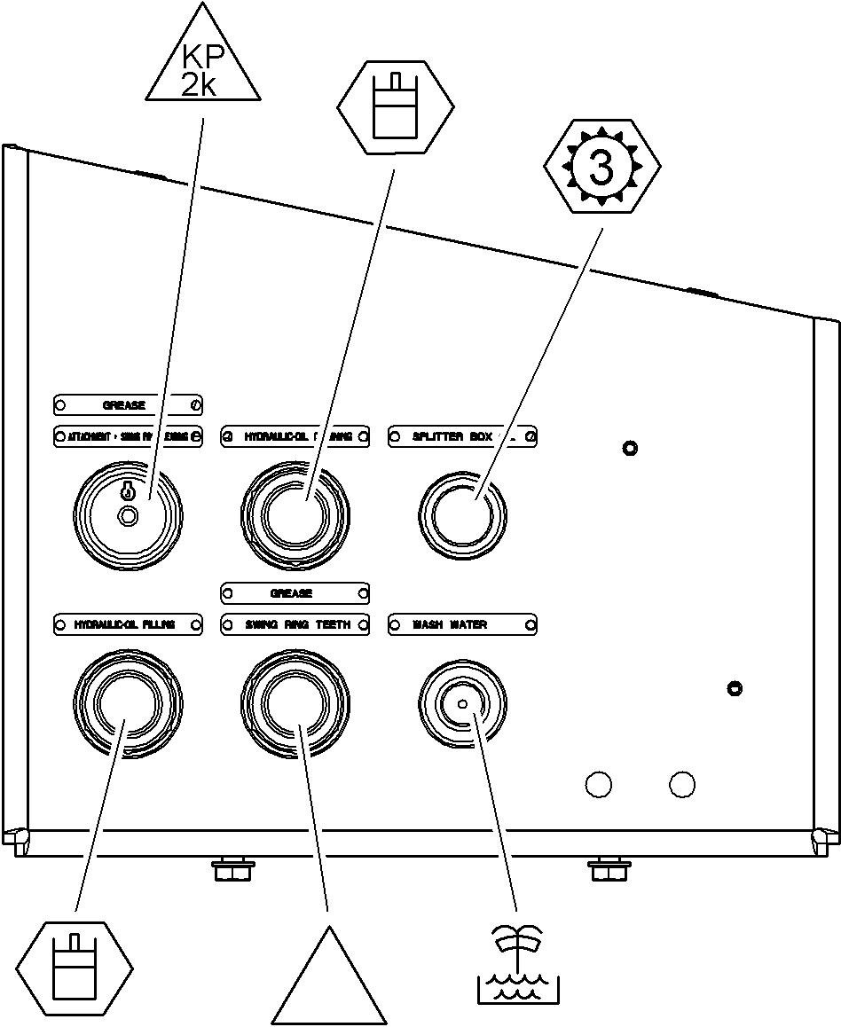
SymbolDisplay
Hydraulic system
Swing gear
Splitterbox
Grease / Swing ring teeth
Grease
Cabin heater
Windshield washer
Check oil level
Oil change
First oil change
Oil analysis
(1)If filled with COB-2, COB-3 or COB-4 gear oil
(2)If filled with COB-1 gear oil
(3)If Bosch splitterbox is installed
(4)If Liebherr splitterbox is installed
(5)Refer to the Operating Manual (section «Lubricating and operating material specifications»)
5.4.3The service trap
Tosimplifytheoilchangeandtherefillingprocedure,thedrainofmajorcomponents is centrally connected to a service trap.
ComponentAdapter WIGGINSFlow max. SplitterboxC-180750 l/min
Hydraulic oil6000 B12100-200 l/min
Windshield washerEC 280 B825 l/min
Depending on the machine, the service trap is different.
5.4.4Lubricant chart
DesignationMediumSymbolClassificationViscosityQuantity*

Electric motorLubricating grease
RefertotheManualforsafety,installationand maintenance of theelectric motor manufacturer.
Hydraulic tankHydraulic oilRefer to section «Lubricating and operating material specifications».
2500 l in hydraulic tank
4050 l in whole circuit
Swing gearTransmission oil
SplitterboxTransmission oil
Swingringrollerbearingracesandgeneral lubrication points
Lubricating grease
Swing ring teethLubricating grease
Refer to section «Lubricating and operating material specifications».
API-GL-5 MIL-L 2105 B, C or D
SAE 90
SAE 80W-90
Refer to section «Lubricating and operating material specifications».
Refer to section «Lubricating and operating material specifications».
2 x 39 L
60 L
200 kg
15 L
Lubricants andoperating fluids
SlipringcontactbowsSpecial corrosion protection and lubrication for contacts
Schutz / Protection
Slipringsbearingsfor low voltage level (if available)
Hinges, joints, locksEngine oil---Rubbersealondoors and trim panels Silicon spray ortalc ----
5-3 Lubricant chart
*The given quantities are onlyguidelines. Check fluidlevel after eachchange or refilling.
5.4.5Operating material chart
*The given quantities are onlyguidelines. Check fluidlevel after eachchange or refilling.
copyright © Liebherr-Mining Equipment Colmar SAS 2021
5.4.6Service trap
For safety reasons and ease of maintenance, oil for the connected components shouldonlybedrainedandrefilledviathequick-changecouplingsintheservicetrap However,thesecomponentsarealsoequippedwithoildrainvalves,seedescription for oil change procedure of these components.
To lower and lift the service trap
This section is applicable only for machines equipped with a service trap hydraulic operated.
Fig. 5-9 Control box E1022_2 and control board
Whentheservicetrapislowered,theserviceplateisaccessiblefromthegroundlevel.
Theservicetrapcanbemovedupanddownvia thefourpushbuttons onthecontrol box E1022_2 at the lower end of the access ladder.
The service trap can also be operated with the motor stopped.
Lower the service trap from its uppermost position: Push the button S161 to unlock the trap, Push the button S162 to move the trap downward.
Lift the trap:
Push the button S159 until the red warning light H69 goes off on, Push the button S160 to lock the trap until the lock pin get its stop position.
The lighting of the red warning light H70 shows that the locking pin of the trap is not in end (locked) position.
The lighting of the red warning light H69 shows that the trap is not in upper end position.
ThelockingofthetrapthroughthebuttonS160ispossibleonlywhenlight H69goes off.
Caution!
Forsafetyreasons,theexcavatorcanonlybeoperatediftheservicetrapislocked in its uppermost position. If not, the red warning light H70 comes on. This means that the swing and travel movements stay locked.
This safety measure can be bypassed as long as the button S122 on the control board is activated.
5.5Lubricating and operating material specifications
Liebherr-Mining Equipment Colmar SAS only gives approval for the Liebherr-branded lubricants and operating materials given in this manual.
Forotherlubricants,fluidsorgreases,Liebherr-MiningEquipmentColmarSASgives technical specifications for their related applications. It is the responsibility of the lubricant, fluid or grease supplier to check, justify and ensure to the owner of the machine that the lubricant, fluid or grease obeys these specifications sustainably.
5.5.1Lubrication for the electric motor
RefertotheManualofsafety,installationandmaintenanceoftheelectricmotormanufacturer.
5.5.2Hydraulic oil specifications for LIEBHERR Mining excavators
Hydraulicoilsmustmeettherequirementoutlinedbelow(dependingontemperature range).
Non-compliancewiththeserequirementsshallvoidallwarrantyandliabilitybyLIEBHERR.
LIEBHERR recommends maintaining the hydraulic oil to a cleanliness level that meets contaminant code 20/18/15 according to ISO 4406.
Maximum water content of hydraulic oil : <0,1%.
Caution!
According to the oiltype used for the hydraulic system, the fans speed regulation must be set specifically ("STANDARD", "COLD" or "EXTRA-COLD").
livered without arctic kit, it is set to "STANDARD"at delivery.
an arctic kit, it is set to "COLD" at delivery.
Beforefirststartoftheexcavatororifanoiltypechangeisdoneafterwards,thefans speed regulation setting must be checked and corrected if necessary.
Contact LIEBHERR Customer Service.
LIEBHERRoils for hydraulic system
Requirements
A Ambient air temperature
B Operating range
C Extra-cold start range if excavator fitted with operating Liebherr arctic kit (with warm-up instruction)
Fans speed regulation settings
LIEBHERR oilfans speed regulation setting
LiebherrHydraulic Plus"STANDARD"
LiebherrHydraulic Basic 68"STANDARD"
Liebherr Hydraulic Basic 100"STANDARD"
LiebherrHydraulic HVI"COLD"
Liebherr Hydraulic Plus Arctic"EXTRA-COLD"
Engineoils for hydraulic system
Requirements
Lubricating and operating material specifications
A Ambient air temperature
B Operating range
C Extra-cold start range if excavator fitted with operating Liebherr arctic kit (with warm-up instruction)
Caution!
Minimumambientairtemperatureforextra-coldstartdependsonoiltypeandbrand and equals to oil pourpoint temperature +5 degrees K.
Recommended and approved are mineral engine oils, which conform to one of the following specifications:
APIACEAMercedes-Benz
CK-4E7228.1
CJ-4E5228.3
CI-4E3228.5
CH-4E2
CF-4
Fans speed regulation settings
CF Engine oilfans speed regulation setting
SAE10W30"STANDARD"
SAE10W40"STANDARD"
SAE20W-20 (ISO VG68)
"STANDARD"
SAE15W40"STANDARD"
SAE30 (ISO VG100)
SAE 10W (ISO VG46)
Hydraulic oils for hydraulicsystem
Requirements
"STANDARD"
"EXTRA-COLD" or "COLD"
A Ambient air temperature
B Operating range
C Extra-cold start range if excavator fitted with operating Liebherr arctic kit (with warm-up instruction)
Caution!
Minimumambientairtemperatureforextra-coldstartdependsonoiltypeandbrand and equals to oil pourpoint temperature +5 degrees K.
Hydraulic oils must contain dispersant and detergent additives and conform to one of the following specifications:
Diniso
51524-2 (HLP, HLP-D)ISO 11158 (HM)
51524-3(HVLP,HVLP-D)ISO 11158 (HV)
Additional requirements:
Test/RequirementStandard/ReferenceRequired level/ Performance
Shear stabilityDIN 51350-6 CEC L 45-A-99
Fans speed regulation settings
KRL/C < 15%
Hydraulic oilfans speed regulation setting
ISO VG68"STANDARD"
ISO VG100"STANDARD"
ISO VG46"COLD"
ISO VG32"EXTRA-COLD"
Warm-up procedure
The black bar C indicates that the ambient temperatures are maximum 20 °C below the operating range B
IntheeventofacoldstartatanambienttemperatureincludedinrangeC,thefollowing warm-up instruction applies to the hydraulic oil:
1. Starttheelectric motor. Carefully activatethe working hydraulic circuits. Operateahydrauliccylinder(Stickforexample)andmovethemtothestopquicklyand many times. After approx. 5 minutes, start the travel hydraulic circuits.
Warm-up duration: approx 10 minutes
For temperature below the limits A :
2. Preheat hydraulic oil in the tank before starting the electric motor.
Biodegradable hydraulic oils
The use of biodegradable hydraulic oils must in any case be discussed with LIEBHER MINING EQUIPMENT COLMAR SAS.
Do not mix biodegradable hydraulic oils from different suppliers and never mix with mineral oils.
Donotusevegetable oils as they do notpossessthenecessarythermalstability.
Depending on the temperature range, LIEBHERR recommends its poly-alpha-olefin (PAO, HEPR) oils, that are biodegradable according to CEC-L-103-12 (21 days, > 60%, primary decomposition):
Liebherr Hydraulic Plus or Liebherr Hydraulic Plus Arctic
If these oils are not available locally or if further specifications are required, use one of the following oils (before choosing an oil, contact our Customer Service):
Fully saturated synthetic ester-based oils, HEES
Depending on thetemperature range, the viscosity grade of the HEES oilmust conform to the above specifications for hydraulic oils.
Caution!
LIEBHERRrecommendstolimittheuseofHEESoilstoareaswhereHEESoilsare mandatory by local regulations. Lifetimeofcomponentsmadeoutofrubbermaterialsuchashoses,seals,compensators might be reduced while using HEES oils!
When mixing ester-basedbiodegradable hydraulic oils with mineral oils, there is a riskofagressivechemicalreactions,whichmightdamagethehydraulicequipment.
Hydraulic oil selection forcold climate conditions
When a LIEBHERR Mining excavator works under cold climates conditions, in any case, the appropriate arctic kit must be installed.
Oil must match the above prescription for engine oils or hydraulic oils. ature must be at least 5 K below the minimal air ambient temperature.
mperature > 160°C (recommended > 200°C).
The operating range of the arctic oil depends on the ambient air temperature and must be checked as follow: stays below +20°C, the oil viscosity at +50°C (oil temperature) must be over 16 cst. stays below +30°C, the oil viscosity at +60°C (oil temperature) mustbe over 16 cst.In this case, thefans speed regulation "EXTRA-COLD" or "COLD" must be selected. stays below +40°C, the oil viscosity at +70°C (oil temperature) mustbe over 16 cst.In this case, thefans speed regulation "COLD" must be selected.
In this case, the fans speed regulation "EXTRA-COLD" must be selected.
ContactLIEBHERRCustomerServiceforadditionalquestionsaboutoilselection.
Oil mixing
In principle, oil mixing between two different oil types must be avoided. Mixing two different oil types leads to an unknown lubricant with resultant unknown physical copyright © Liebherr-Mining Equipment Colmar SAS 2021 properties(viscosity, pourpoint,flashpoint,ageing behaviour,lubricity, reactionwith additives...).
However, if mixing is absolutely necessary, respect the following maximum mixing proportions:
, or LIEBHERR oils with mineral oils, or hydraulicoilswithmineraloils,ortwodifferentmineral oilstogether,ortwodifferent hydraulic oils together: max. 10% max. 2% or mineral oils or LIEBHERR oils:
Hydraulic oil changeintervals
Oil changes at pre-set intervals (mineral oils and PAO oils only)
This procedure is applicable only for mineral oils and PAO oils. If you use HEES biodegradable oil, refer to the next section.
A Mineral oils and PAO oils hOperating hours
Liebherrrecommendsthatyousamplethehydraulicoilevery500operatinghours (refer to the section "Condition monitoring with oil analysis"). Change the hydraulic oil every 2000 operating hours.
Oil changes at optimized intervals
Thisprocedureisapplicableformineraloils,PAOoilsandHEESbiodegradableoils.
A Mineral oils and PAO oils
B HEES biodegradable oils h Operating hours
1 First oil sample
2 Second oil sample
3 Next oil samples at regular intervals
You can extend the oil change intervals (up to 6000 operating hours and possibly even more) as long as the properties of the oilare satisfactory.
Get a sample of the new hydraulic oil.
IfyouusemineraloilorPAOoil, youmustsamplethehydraulic oilevery 500operating hours after the first 1500 operating hours.
If you use HEES biodegradable oil, you must sample the hydraulic oil every 250 operating hours.
Changethehydraulicoilimmediatelyiftheresultsoftheanalysisarenotsatisfactory (refer to the section "Condition monitoring with oil analysis").
5.5.3Swing gear oils
Note!
Foragivenmachineoperatingtemperaturerange,andifdifferentviscosity grades areapprovedaccordingtothefollowingspecifications,alwayschoosethelubricant with the highest viscosity grade.
Caution!
Gears flushing is necessary when switching from mineral oil to synthetic oil. Use new oil to flush the gear when switching from mineral oil to synthetic oil. Flushing with cleaning fluid or Diesel fuel is not permitted.
Usegearoilmeetingfollowingviscosityclassesandspecifications(dependingonthe ambient temperature):
* COB-1: Gear oil according to DIN 51517, part 3, CLP-HC(1) (1) HC / Synthetic carbon hybrid (poly-alpha-olefin PAO)
TEST / REQUIREMENTSTANDARD / REFERENCE REQUIRED LEVEL / PERFORMANCE
Relative scuffing load-carrying capacity A/8.3/90DIN ISO 14635-1>14
Relative scuffing load-carrying capacity A/16.6/140DIN ISO 14635-1>12
FVA-FZG micro-pitting load capacity GT-C/8.3/90FVA Information sheet no. 54/I-IV
GT-High
FE-8 roller bearing wear tests 7.5/80/80 and 7.5/100/80DIN 51819-3Pass (excellent)
FLENDER AG approval-Approved
Tab. 5-5
FVA = Forschungsvereinigung Antriebstechnik e.V. ("Research association for drive technologies")
FZG = ForschungsstellefürZahnräder und Getriebebau der TUMünchen ("Gear Research Center of the Technical Universityof Munich")
** COB-2: Gear oil according to DIN 51517, part 3, CLP
TEST / REQUIREMENTSTANDARD / REFERENCE REQUIRED LEVEL / PERFORMANCE
FVA-FZG micro-pitting load capacity GT-C/8.3/90FVA Information sheet no. 54/I-IV
GT-High
FE-8 roller bearing wear tests 7.5/80/80 and 7.5/100/80DIN 51819-3Pass (excellent)
FLENDER AG approval-Approved
Pour point temperatureISO 3016VG220: TPourpoint <-15°C
VG320:TPourpoint <-15°C
VG460:TPourpoint <-10°C
VG680: TPour point < -5°C
Tab. 5-6
*** COB-3: Gear oil according to API classification GL5
TEST / REQUIREMENTSTANDARD / REFERENCE REQUIRED LEVEL / PERFORMANCE
API classificationGL 5-
Scuffing load capacity FZG test A/8.3/90DIN ISO 14635-1>12
MIL-L2105 B/C/D-
MAN342 type M1-
Mercedes Benz235.0-
ZF FriedrichshafenTE-ML 05A, 16C, 17B, 19B, 21A -
Tab. 5-7
**** COB-4: Gear oil according to API classification GL5
TEST / REQUIREMENTSTANDARD / REFERENCE REQUIRED LEVEL / PERFORMANCE
Tab. 5-8
Lubricating and operating material specifications
**** COB-4: Gear oil according to API classification GL5
API classificationGL 5-
Scuffing load capacity FZG test A/8.3/90DIN ISO 14635-1>12
MIL-L2105 D, PRF-2105EMAN342 type N-
ZF FriedrichshafenTE-ML 05A, 07A, 16D, 21A -
5.5.4Splitterbox oil
Use gear oil with viscosity classification SAE 90 or SAE 80W90 and meeting specifications API-GL-5 and MIL-L-2105 B, C or D.
5.5.5Lubricating grease
The machine has two lubrication systems: and the swing gear bearings e swing ring teeth.
For each of these systems, use grease that meets the specifications that follow.
Specifications for standard applications (ambient temperature of more than -20°C)
Specification
MethodUnit
Swing ring bearings, attachment bushings,swing gear bearings
Swing ring teeth
Temperature range-°C-20 to +120
NLGI grade--2
Base oil viscosity at 40°CASTM D445 ISO 3104
Dropping pointIP 396 - ISO 2176 ASTM D566

1) One of the two methods.
2) Or equivalent test under responsibility of the lubricant manufacturer.
Lubricating solidsUnitSpecification
Greases which use calcium simple soap as thickener are not permitted.
Grease selection for cold climate conditions
For application below -20°C: given applications. grade must be adapted.
Lubricating and operating material specifications favored for low temperature applications (below -20°C) and are mandatory for operations below -40°C. ication system must be tested at minimum ambient temperature of the application.
Additional requirement:
Grease mixing
When the grease is changed from one type of grease to another, the basic recommendationistoremovealltheoldgreasefromthesystem.However,thefullremoval from the system is not possible especially in the swing ring and in the swing gear bearings.
Thecompatibilityoftwodifferentgreasesisnotgivenandcancausecatastrophiclubrication failures. Lubricating greases made of different thickener base must never bemixedtogether.Notonlythethickenertype,butalsothebasicoilandtheadditives treatmentshavetobeconsidered. Thecompatibility ofgreases shouldbe evaluated accordingtoASTMD6185.Furthermore,awrittenstatementofthelubricantsupplier must justify greases compatibility.
5.5.6Other lubricants
Refer to the table that follows for other lubricants.
LubricantDescription / manufacturer
Contact spray for slip ringsCramolin
Lubricant for pistons, piston nuts and piston bearing installations on the hydraulic cylinders
Special anti-corrosive material for installation areas of sealingelementsonhydraulic cylinders
Anti-corrosion grease for open piston rods (cylinders that do not move often or transportation)
Gleitmo 800
Castrol-Tarp
Liebherr Cylinder Protect