25 minute read
Control and operation


The access and the outfit of the cab
Move the lever 1.
The quantity of water running through the heat exchanger can be regulated. Iftheregulatorispushedallthewaytotherear,themaximumquantityofcoolant flows to the heater.
Set the desired air flow viabutton S12 andstart theheaterunit by pushing S205
Move the lever 2
The quantity of fresh air recirculated and entering the cab is regulated.
Note!
The bestheatingeffect canbereachedwhenthe air is recirculated, whichmeans, the lever 2 should be pushed all the way to the front. In this position, a small quantity of outside air is mixed with the recirculating air in the cab.
Quickly defrost the windshield
Direct the warm air flow via the vents to the front, Push the sliding regulator 3 all the way to the rear. Sothemaximumairflowisblownviatheventsinthestepontothewindshield. Whenthelever3 ispushedalltheway to thefront,partofthewarm airflow isblown against the left side window.
Overview of the air conditioner
The cab has an air-conditioning system as standard. The air-conditioning system is used to cool and ventilate the cab.
Air conditioner operation
Adjust the air conditioner fan
Use button S1
The electric motor must be running before the air conditioner blower is turned on.
Turn on theair conditioner compressor and the condenser fan
Use button S2.
The air conditioner can only be turned on if the evaporator fan unit is turned on via button S1
Select the desired air flow
Use the rotary switch S1
Set the desired air temperature
Use the rotary switch S2
Adjust the direction of the cold air flow
Use the vents on the evaporator unit.
For air conditioner operation during the summer time
Push the lever all the way to the front.
Turn the heaterblower off via button S12
Dehumidify the air in the operator’s cab
In case of very high humidity inside the cab during the colder season, the air conditioner can be operated for a short while simultaneously with the heater in order to eliminate the excess of humidity and the condensation.
For best efficiency, selecta highevaporator air flow via therotary switch S1 and operate the heater with recirculated air.
3.3Setting the machine into operation
Bringing the machine safely into service und the machine each time before starting it. area of the machine. itate the fight against fire in case of. against unintended movement. vicinity of the machine that it is about to start by sounding the horn.
Adjusting the operator’s standing position controls in such a way that you are able to work comfortably and safely. e must be set to the insulation position throughout operation.
Protection from vibration - seat adjusting and height of the operator. structions.
Utilisation in confined spaces el-operated heaters inadequately ventilated spaces. Before starting in closed areas, ensure adequate ventilation. Follow the regulations which apply for the particular area of use.
Starting the machine safely
l and tilt the safety lever up. alertpeopleinthevicinityofthemachine. start the engine in accordance with the regulations given in the operating instructions.
tion.Ifnecessary,opendoorsandwindowstoensuresufficientfreshairsupplies. eratingtemperature.Lowoiltemperatures make the control unit react sluggishly.
travelandswinggearbrakes,thesteeringandthesignallingandlightingdevices. Lighting devices must always be clean.
Stopping the machine safely
incline, chocks should be used to secure it from rolling away.
ispossible,aligntheuppercarriagewith the undercarriage so that the sprockets locate at the back-end. This is the only one position which enables a secured access toevery maintenance locations on the uppercarriage.
able. brakes.
lever up before leaving the cab.
secure the machine against unpermitted use and vandalism.
3.3.1Start / stop the machine
General information
Note!
Whenusingthemachineataspecificheightabovesealevelandinconnectionwith certainoutsidetemperatures,theperformanceandservicelifeoftheelectricmotor is decisively affected. Under theseconditions,thereis alsoan increasedriskofhydraulic oil overheating.
Before initial start up
Check the insulation resistance
Before initial start up and after alongperiodof non-use, andbefore theexcavator is connected to the power supply, check the insulation resistance:
The resistance values must never be less than the minimum authorised resistances given in the instruction manual of the electric motor.
If insulation resistances are less than the minimum authorised value: Refer to the procedure in the instruction manual of the electric motor.
Check direction of rotation of electric motor
Beforeinitialoperation,orbeforerestartingtheelectricmotorafterrepairstotheelectrical system, check the direction of rotation of the electric motor. Briefly start and stop the motor, and compare the direction of rotation to the arrows marked on the motor.
Activities before starting
Caution!
It is only possible to extinguish a source of fire when this one is accessible. Before starting, unlock all locks on the panelling of the hydraulic excavator. In the event of fire, the doors can be opened immediately and the fire extinguished.
Arrangement of locks: refer to chapter Maintenance.
Caution!
The activities below involve scald or burn hazards due to the high temperature of the hydraulic oil when the machine is at operating temperature. Read the Maintenance chapter in order to get informations about carrying out these activities.
Before starting the machine, the following activities should be carried out on a daily basis: ing air intake.
Turn on the electrical system
0 Off
1 Contact position
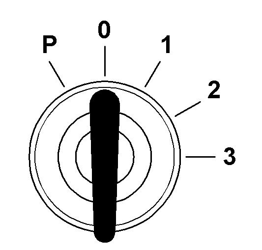
2 Not used P Park position
3 Start position
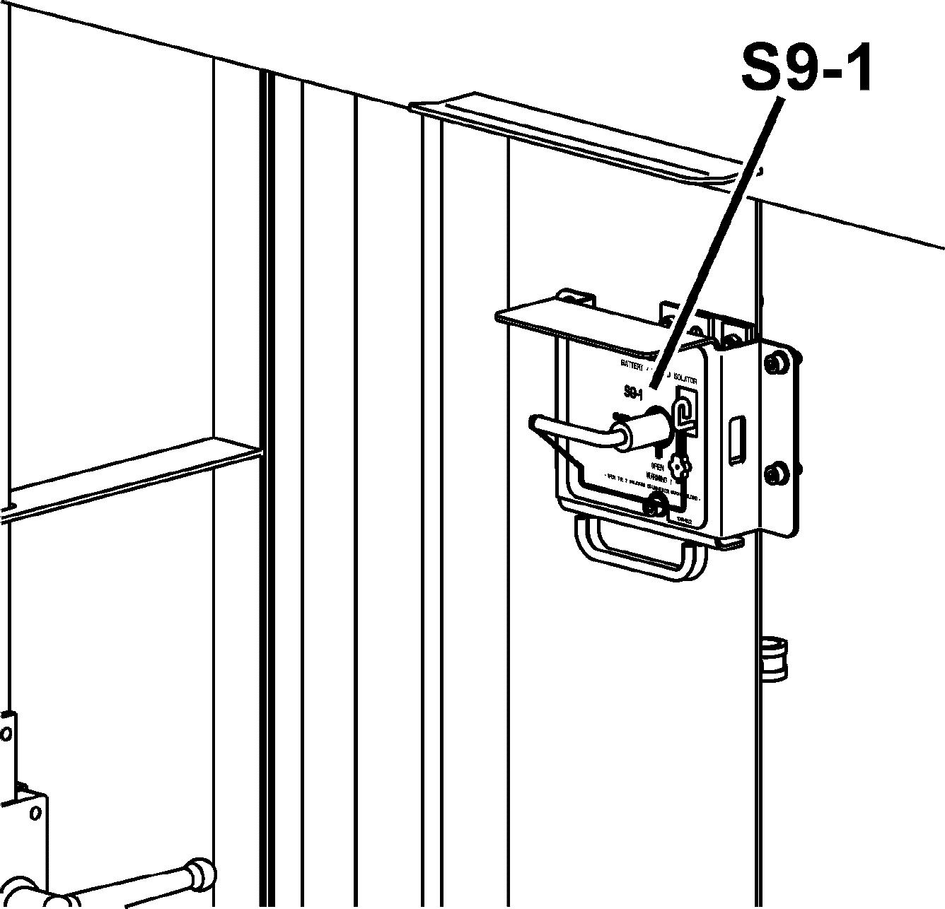
Turn on the high voltage circuit
Close the battery switch S9_1.
Makesurethattheexcavatorisconnectedtoandsuppliedwithelectricpowerby the power station or the field switch.
Turn ignition key S1 to contact position. Push button «Control ON» S183 on control board.

The high voltage circuit operates.
H183 in S183 button comes on.
The display and the control unit run through a self test.
Make sure all indicators function properly after turning the electrical system on, i.e. the light emitting diodes (indicator lights and gauges) turn on for a short time thenthecompletefieldoftheLCDindicator200turnsmomentarilyblack(thematrix indicator is energised completely for a short time).
Note!
If no automatic check of the keyboard and monitoring screen is carried out when the ignition keyis in the contact position, check that the main battery switch is set to on.
Turn on the low voltage circuit
The high voltage circuit is on.
For machine with option «Vessel - excavator data link», make sure that button «External supply 440V» S186 is on position «0».
Push button «Control 440V ON» or «Control 400V ON» S207 on control board. The low voltage circuit operates. The 24V control circuit operates. H120 in S207 button comes on.
Turn on the external 440V supply for machine withoption «Vessel- excavator data link»
Make sure that the high voltage circuit is off.
Close the battery switch S9_1
Makesurethattheexcavatorisconnectedtoandsuppliedwithelectricpowerby the power station or the field switch.
Turn ignition key S1 to contact position.
Turn button «External supply 440V» S186 to position «1» on control board. Thelow voltage circuit of theexcavator issupplied with440Vcomingdirectly from the vessel.
Service interval display

Fig. 3-52 Service interval request
After the automatic check, any service interval that may be due will be indicated by a graphic symbol.
In place of the operating hours information, the number of hours relating to the service interval required will now be displayed.
The service interval request will go out after approx. 8seconds.
Start the electric motor
3-53 Control board
Depending on the machine, the start procedure of the electric motor is different.
Standard start procedure
Make sure that the high and low electrical circuits have been turned on as described above.
Push button «Motor ON» S181 on control board. The motor starts. H112 in S181 button comes on.
Caution!
Inordertopreventtheelectricmotorfrom overheating,motorstartingattemptsare limited for a given time frame. You must observe a sufficient time interval between two consecutive starting attempts.
Whenthemotoriscold,donotrestartmorethan5times.Thenwaitabout1hour before restarting.
When the motor is already warm, we recommend that you do not restart more than3times,waitingabout10minutesbetweentwoconsecutivestartingprocedures.
Start procedure for option «Vessel - excavator data link»
3-54 Control board
Make sure that the high and low electrical circuits have been turned on as described above.
Push button «Motor ON» S181 on control board.
The excavator sendsa start request to the vessel.
If indicator H176 «Start allowed» comes on: The electric motor starts. H112 in S181 button comes on.
The excavator sends the information «Motor ON» to the vessel.
If indicator H175 «Start not allowed» comes on: It is not possible to start the electric motor.
Turn the high and low electrical circuits off.
If indicator H177 «Sequence in progress» comes on: It is not possible to start the electric motor immediately. Wait until the indicator H176 orH175 comes on.
Caution!
Inordertopreventtheelectricmotorfromoverheating,motorstartingattemptsare limited for a given time frame. You must observe a sufficient time interval between two consecutive starting attempts.
Whenthemotoriscold,donotrestartmorethan5times.Thenwaitabout1hour before restarting.
When the motor is already warm, we recommend to donot restart more than3 times, waiting about 10 minutes between two consecutive starting procedures.
Warm-up procedurefor hydraulic circuit
If the excavator is started when the exterior temperature is below 0°C, the operator must do the warm-up procedure:
Make sure that the hydraulic oil temperature is sufficient (refer tolubricating sectioninchapter5)to dothisprocedure.Ifthistemperatureisnotsufficient whena preheating system is installed onthe excavator, keep preheating.
Start the electric motor and let it run without load during the first 3 to 5 minutes and makesure that no error symbols are shownon the monitoring display (refer to the functions of the display in chapter3).
Step 1 - Open louvers and tarpaulins (if installed).
Step 2 - Carefully activate the working hydraulic circuits. Do not reach end positions of piston rod. Operate all movements at reduced speed: ttachment. Activate cylinder in order below and repeat 10 times before moving to next cylinders: wise on approximately 1/2 turn. Repeat 4 times in each direction.
Step 3 -Repeat step 2 a second time.
Step 4 -Repeat step 2, with reaching end position of piston rod.
Step 5 -Repeat step 4 a second time.
Step6-Checkoiltemperatureinhydraulictank.Ifoiltemperatureisunder10°C, repeatstep4untiloiltemperaturereaches10°C.Ifoiltemperatureisabove10°C, move to step 7.
The step 7 that follows is applicable only to crawler excavators.
Step 7 - Start the travel hydraulic circuits very slowly forward and backward on approximately 10 meters. Repeat 4 times.
The excavator can now be operated.
Notes after starting the motor
Runtheelectricmotoruntilthehydraulicoilisatoperatingtemperature.Thecontrols operate sluggishly at low oil temperatures. Move the machine carefully to test the function of the swing brakes.
Check that the attachment operates perfectly.
Stop the electric motor
Push the button S182 «Motor OFF». The electric motor is stopped. The indicator light H112 goes off.
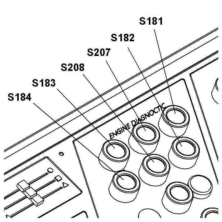
Turn off the low voltage system (400V or 440V)
Push the button S208 «Control OFF 400V». The low voltage system is turned off. The indicator light H120 goes off.
Option «Vessel - excavator data link»
Push the button S208 «Control OFF 440V». The low voltage system is turned off. The indicator light H120 goes off.
Turn off the high voltage system (6,6kV)
Push the button S184 «Control OFF». The high voltage system is turned off. The indicator light H113 goes off.
3.3.2Emergencyand safetyoperations Emergency shut down
For emergency shutdown, you can: S1 to the «0» position. S100-1, S100-2, S100-3, S100-4 (if installed), S100-5 or S100-6 (optional). For location of emergency stops, refer to section «Electrical system» in chapter 5 of this manual.
In the two cases:
The main circuit breaker Q2A opens.
Thelowvoltagesystem(heater,airconditioning,batteriescharger,etc.)isdisconnected.
The electric motor is stopped.
If the machine has a 45° access ladder, the ladder is automatically lowered when an emergency stop is operated.
For machines with option «Vessel - excavator data link», if you push an emergency stop:
The machine sends the information «Remote trip to CB» to the vessel.
Caution!
Use this shut off method only in emergencies.
After a shut down via an emergency stop button, you must unlock it before attempting to restart.
Safety controls for hydraulic pumps
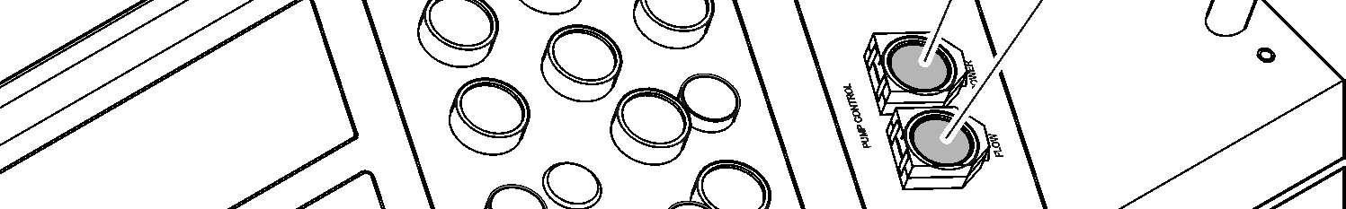
S73 Pumps power safety control
Pumps power safety control
S74 Pumps flow safety control
During normal operation of the excavator, the electronic horsepower control continuouslyadjuststhepumpflowtothepressurelevel oftheworkingcircuits.Ifatrouble occurs in the circuit of the regulator, the pumps are swivelled back to minimal flow. However it remains possible in this case to carry on the working with the machine (with somewhat reduced power) by pushing the button S73
Pumps flow safety control

Duringsafetyoperation,apresetvalue fortheflow ofthehydraulic pumpsisactivated by pushing the button S74.

Safetycontrols for electric system
H114 Safety batteries

Electric system voltage monitoring
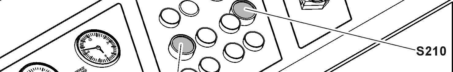
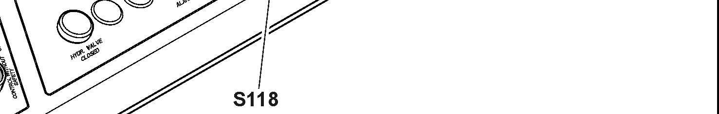
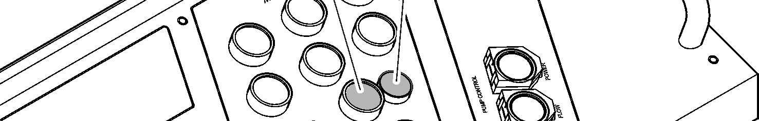
S118 Voltage monitoring relay
S185 Safety 24V
S210 Reset default end sensor S1/S2
The excavator has an overvoltage and undervoltage protection.
If an overvoltage or undervoltage is detected in the electric circuit: The electric motor is stopped. The indicator light in the button S118 comes on.

Push the button S118 to acknowledge the information.
Battery power supply
If the power supply from the electric plant stops, you can switch to the battery of the excavator to supply the service system and to lower the attachment if necessary.
Push the button S185.
Power supply is switch to the battery. The indicator light H114 comes on.
S1 and S2 doors protection
The excavator has protection on high voltage box S1 and low voltage box S2

If the door on S1 or S2 is open: The electric motor is stopped. The indicator light in the button S210 comes on. Push the button S210 to acknowledge the information.
For machine with option «Vessel - excavator data link»
1Control board
H178Indicator / Vessel general alarm
H179Indicator / Emergency trip
Common alarm
If a common alarm is detected on the excavator: The buzzer sounds in the cabin.
The machine sends the information «Common alarm» to the vessel.
Remote trip to CB
Iftheexcavatordetectsanimportantproblem(waterinhighorlowelectricalbox, overvoltage) or if an emergency stop is pushed: H179 comes on.
The machine sends the information «Remote trip to CB» to the vessel.
GA alarms
If a relevant alarm is detected on the vessel: H178 comes on.
The excavator is not more supplied with electricity.
Emergency power supply for boom cylinders
Theboomcylinderscanbemovedforemergencyoperationswithanauxiliarypower unit(APU)connectedtotheemergencycircuitunitof themachine.Thus,theattachment can be raised or lowered in case of failure of the machine or of the hydraulic system.
The following procedures can be done by one person.
Caution!
Only perform the boom movement procedures that follow in case of emergency.
Caution!
Topreventdamagestotheexcavatorhydraulicsystem,theAPUhydraulicoilmust obey the hydraulicoil specifications given in section «Lubricants and operating fluids»ofthismanual(propertiesandqualities,cleanliness,miscibilitywithexcavator hydraulic oil).
Note!
The APU is not supplied with the excavator. 1AFitting3Emergency
In normal operation, the valves 2A and 2B are closed.
Lift up the boom in an emergency case: The valves 2A and 2B are closed.
Remove the cap nuts from the hydraulic fittings 1A and 1B.
Connect the APU on fittings 1A (inlet) and 1B (outlet).
Open the valves 2A and 2B The boom moves up.
Close the valves 2A and 2B when the boom is in the wanted position.
Put down the boom:
The valves 2A and 2B are closed. Measure the servo pressure value. Refer to the Service Manual.
If the servo pressure is less than 30 bar: Close valves 2A and 2B
Remove the cap nuts from the hydraulic fittings 1A and 1B
Connect the APU on fittings 1A (inlet) and 1B (outlet). The servo pressure increases.
If the servo pressure is 30 bar:
Make sure that the valves 2A and 2B are closed. Push the safety lever down.
Turn the ignition key to contact position.
Carefullyoperate therelatedjoystick tolower the boom until the attachmentisin the wanted position. Refer to section «Attachment control» of this manual.
After emergency operations:
Close the valves 2A and 2B
Disconnect the APU and install the cap nuts again. Check and adjust (if necessary) the oil level in the hydraulic tank.
3.4Working with the machine
Working safely with the machine
withthespecialfeaturesofthejobsite andanyspecialprecautionsandwarningsignals.Examplesofparticularworkenvironments would be on-site or traffic obstructions, the load-carrying capacity of the ground and any requirements to make the job site safe from public use.
ground.
reduced visibility and changeable ground conditions.
power and gas lines on the job site and takeparticularcarewhenworkingnearthem.Ifnecessary,informtheresponsible authorities.
laws, regulations and rules applicable at the place of use.
aerial lines. Do not allow the attachment to come near cables when working near electrical aerial lines. Risk of fatality! Inform yourself about required safety distances. theeventofanytransferofelectricity: squares, observe current traffic regulationsandifnecessary,ensurethatthemachinehasbeenmadesafeasperregulations beforehand. s of poor visibility or darkness. the safety belt securely fastened (if available). mediately. given in the operating instructions. while the machine is moving. doperatedinsuchawaythatitisstable and that there is no danger of overturning. Only known loads may be moved with the attachment; this applies particularly when using the grab. ngitudinal direction when moving and hold the load as close to the ground as possible. start to tip or slide sideways, however, turn the upper structure to face downhill and lower the attachment at the same time. uphill and not side on to the slope. eandnotperpendiculartotheslope,with the uppercarriage aligned with the undercarriage. or you could lose control of the machine. dieselenginemustrunatmaximalspeedandthespeedmayonlybereducedusing the foot pedals. to protect the truck operator. ationsetc.,alwaysuseprotectivedevices specifically designed for the purpose. for the assistance of a spotter. Only permit one person to give you signals. load and to give indications to the with him. chmentcombination,thereisariskofcollisionbetweenthe work tool and the machine (uppercarriage and undercarriage). The greatest degree of care must be taken to avoid damage. chmentcombination,thereisariskofcollisionbetweenthe work toolandthecab,thecab protectionorthe boomcylinders.Thegreatestdegreeof caremust betakento avoiddamagewhenthe hoe teethcomewithinthis area. chmentcombination,thereisariskofcollisionbetweenthe worktoolandtheattachmentparts.Thegreatestdegreeofcaremustbetakento avoid damage. chmentcombination,thereisariskofcollisionbetweenthe liftringoftheattachment andthecaborthecabprotection.Beforeoperating,ensure that there is no risk of collision, especially on excavator with cab elevation. If necessary remove the lift ring. the soil. a ditch without striking the attachment on the ditch walls. tachment has been swung into a wall or any other obstacles. tracted are not permitted, even when working in alongitudinal direction. machine components. plications are required. withsidecutters or that areduringoperations with rocky material. This would prolong the work cycles and may lead to damage to the bucket as well as further machine components. et position may only be employed if the working tool or the attachment does not touch the material. drill into the material is not permitted. slowly back to the ground. hydraulics. This would damage the machine. forbiddentoraisethemachinewiththe dozing blade (e.g. carving at the ceiling when tunnelling). ground collapse under the machine. inthefollowing Miningapplications is not approved or condoned by Liebherr: material is un-blasted and non-fragmented material which requires the boom down (rod side) pressure to exceed 50 bar.
•warnanypersonnelin thevicinitynot tocomeclose totheexcavatorand not to touch it, someone turns off the voltage. e danger zone to a sufficient distance, which had been touched or damaged, has been turned off! cured.
EXCEPTION: excavators used for loading and unloading, see the part "Safe use when loading and unloading (particularly when loading and unloading wood)" on page70.
Otherwise, you must stop the excavator, turn off the radio and keep inside the closed cab until the end of thestorm. s can have various functions. Always check their functions when starting up the machine.
Scaling), without exception.
The use of these Mining methods will result in increased fatigue levels to steel structures and components of the respective Liebherr Mining Machine and thereforewillsignificantlyreducetheexpectedlifetimeofstructuresand/orcomponents.
Working safely with the machine used for demolition application
are subject to specific conditions and mustbefittedwithspecialsafetydevices(forfurtherinformation,contactLiebherr customer service).
ditional safety instructions that follow.
Before the operation of the machine ions are in the specified limits. ly. le local regulations. or special tool you use. andapprovedoperatorprotectivestructures (e.g. FOPS, front protective grid) are not installed. ffects on the machine stability, reduce the height and the speed of the movement. e attachment or special tool. the back-end. safely positioned on the ground. y and the acoustic warning signals. percarriage turns. its specifiedlimits.For moreinformation,
Incorrect use of the machine used for demolition application only by trained specialist personnel.
Do not stop it suddenly. Always move the attachment or special tool slowly and with constant speed movements.
Incorrect use of the attachment or special tool used for demolition application task. front protective grid.
Safe use of a hydraulic hammer or a hydraulicripper
ation, the use of a hydraulic hammer or a hydraulicrippercanresultinvibrations,shocksorstresseswhicharehigherthan in normal use. It may reduce the expected lifetime of structures and/or components.
ripper must be selected with particular care.WhenusingahydraulichammerorahydraulicrippernotpermittedbyLiebherr, warranty for steel structures and machine components will be ceased. n the machine on firm and level ground. ripper designed exclusively for breaking stone, concrete and other breakable materials.
draulic ripper in the longitudinal direction of the machine and with the windshield closed or with a front protective grid.
that nocylinderisentirelyextendedor retracted and that the stick is not in the vertical position.
performing retraction and extension motions of the hydraulic hammer.
time tothesameplace. Changethe breaking point. Too longuninterruptedoperationofthehydraulichammerleadstoanunnecessaryoverheatingofthehydraulic oil.
lic hammer or of the hydraulic ripper to breakstoneorothermaterials.Donotmoveobstacleswiththehydraulichammer. Misuse of this nature would damage both the hammer and the machine.
essure of the dampening accumulator of the hydraulicrippermust be adjusteddepending onthenature of theground and the excavator model.
Safe use of a ripper
where the use of a bucket is not efficienttobreakoutrocks.Thus,theseapplicationsaremoreseverethaninnormal use.
n,theuseof arippercanresultinvibrations, shocks or stresses which are higher than in normal use. It may reduce the expected lifetime of structures and/or components.
ted by Liebherr, warranty for steel structures and machine components will be ceased.
Safe use when loading and unloading (particularly when loading and unloading wood)
attachment raised and the load lifted up; this applies, for example, when loading and unloading wood.
ewillbedisplacedupwardsinthevertical direction. The driving characteristics of the machine will thus be influenced persistently, e.g. through reduction of the dynamic stability. The following instructions are therefore to be observed at all times: red machinecharacteristics and environmental conditions.
noeuvres.
aking, accelerating and changing direction.
ed the upper structure to the driving position. when the attachment is raised. cab.
there is a risk of objects falling from above.
such as logs, is dependent on length, diameterand specificweight.Theinfluencingvariablespresent inanatural product, such as moisture, must be noted.
with grabs require the machine operator to receive special instruction and training. sufficient training and practical experience.
Safe use of machines with tower elevation
gravity of the machine will be displaced upwards in the vertical direction. The driving and work characteristics of the machine will thus be influenced persistently, e.g. through reduction of the dynamic stability.
themachinemustbealignedhorizontally before use. In horizontal alignment, the centre of gravity of the uppercarriage is over the centre of the undercarriage, which reduces the risk of tilting.
tilt despite being aligned!
The following instructions are therefore to be observed at all times: as close as possible to the machine (Caution! swinging grab) and hold the load close to the undercarriage and above the substrate. ttachment or uppercarriage abruptly.
When moving the machine: e undercarriage (transport position). holes and uneven surfaces jeopardize the stability of the machine. red machine characteristics (high centre of gravity) and environmental conditions. noeuvres. rection. direction in order to prevent unacceptable banking of the machine. slowly!
When loading and unloading: the uppercarriage out of the transport position. act surface of the support (load carrying capacity of the substrate). A support subsiding would have disastrous consequences!
Protection from vibration
building machinery are mainly the result of the type andmethodofuse.Thefollowingparametersinparticulararedecisiveinfluences: ng, brakes, contro control elements when driving and working. determinesthevibrationalloadssincehe selects the speed, gearbox ratio, working method and route himself. This means that there is a wide range of different vibrational loads for the same machine type. hydraulic excavators, this should be a seat which corresponds with EN ISO 7096). be adjusted depending on the weight and height of the operator. justmentmechanismsregularlyandensure that these seat characteristics remain as per th structions. ine, particularly with respect to: tyre pressure, brakes, steering, mechanical connections etc. ment jerkily. chinespeedtosuittherouteasfollows: calculate in sufficient time to carry out any work required. able) which reduce vibration for machines that are driven frequently. If such auxiliary systems are not available, regulate speed to avoid "oscillating" the machine.
Whole-bodyvibrationalloadforthemachineoperatorcanbereducedifthefollowing recommendations are observed: attachment parts andauxiliary devices for eachpart of the job.
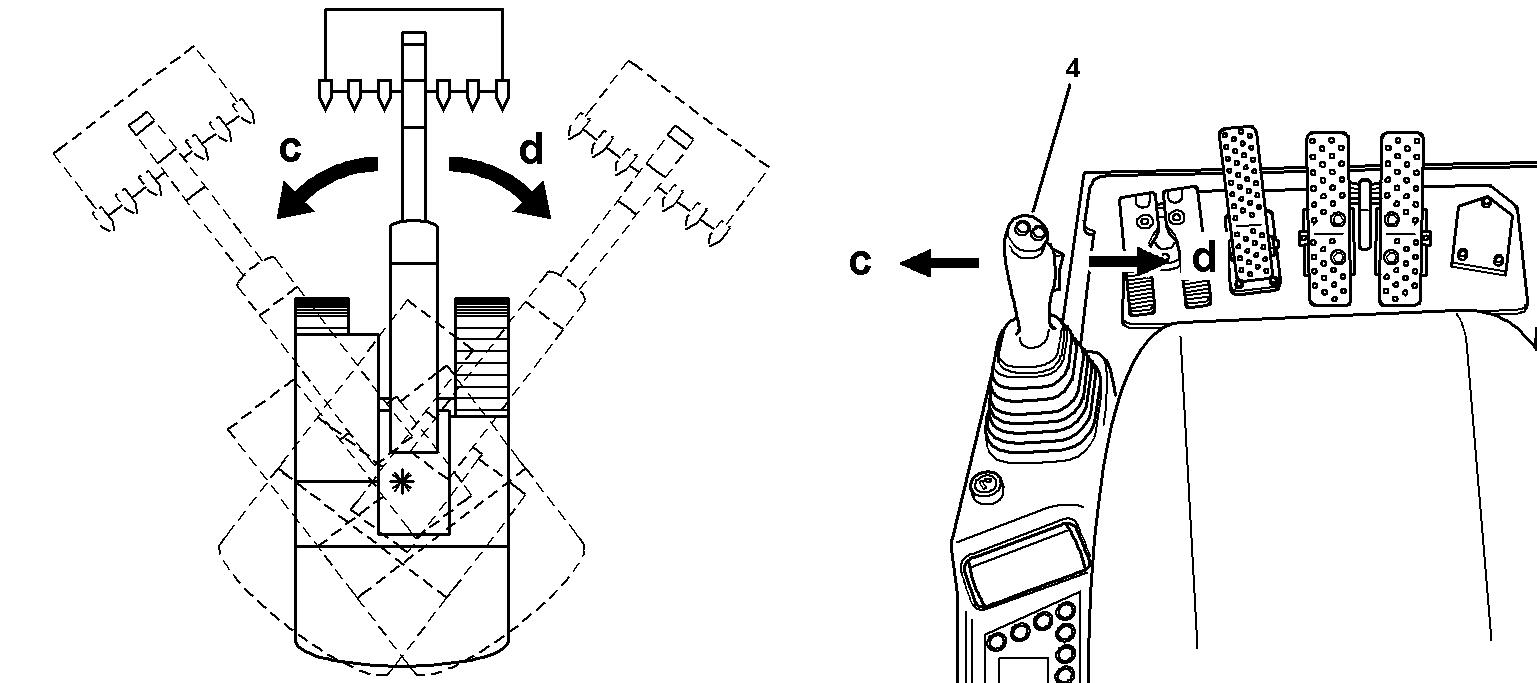
3.4.1Uppercarriage swing movements
The swing movements of the uppercarriage are controlled by the left joystick.
Rotating the uppercarriage
Push the left joystick to the left c: The uppercarriage rotates to the left. Push the joystick to the right d: The uppercarriage rotates to the right.
Braking the uppercarriage
Themachineisequippedaswellwithanhydraulicaswithamechanicalswingbrake.
The hydraulic swing brake
Let the left joystick move back to neutral position. The hydraulically swing braking of the uppercarriage takes place. In normal working conditions, the braking efficiency is sufficient to bring the uppercarriage to a standstill rapidly.
Move the left joystick in the opposite direction. The maximum hydraulic braking actionof the uppercarriage is achieved.
The mechanical swing brake
Themechanicalbrakeisanegativelyactingmultidiscbrakewhichisintegratedinthe swing gear. It allows to stop the uppercarriage in any desired position (for parking, when working on a slope, ...).
Press "Swing brake" button S17 Swing brake is applied. LED in the button illuminates. Press the button again. Swing brake is released. LED in the button goes out.
Caution!
Thebrakeonlyapplieswhentheuppercarriageisnearstandstillandifnoswingmotion is actuated with the joystick.
To stop the uppercarriage when working on a slope: Use the joystick to reduce the uppercarriage speed. Press button S17 to operate the swing brake. Move the joystick back to "0" position only after the brake operates.
To check the mechanical swing gear brake: When the uppercarriage is stationary. Press button S17 to apply the mechanical swing brake
Push the left joystick to the right and then to the left as far as the stop. If the swing brake function is OK, the uppercarriage does not start swinging.
Semi-automatic swing brake control (optional equipment)
Press button S17 to release the swing brake. LED in the button goes out. The swing gear brake is in mode semi-automatic and can now be controlled as follows by the rocker switch S57:
Tilt down the rocker switch S57 on the joystick handle. Thebrakeisappliedwhentheuppercarriageisatstandstill,respectivelyitapplies as soon as the uppercarriage speed gets lower than a limit value.
Tilt up the rocker switch S57. The brake remains released permanently.
Note!
TheredLEDbesidethebuttonS17islightinginanycasewhenthebrakeisapplied. If this light does not go out when the rocker switch S57 is tilted up, the button S17 must first be pushed to pre-select the semi-automatic mode.
Caution!
Thebrakeonlyapplieswhentheuppercarriageisnearstandstillandifnoswingmotion is actuated with the joystick.
To stop the uppercarriage when working on a slope: Tilt down the rocker switch S57
Use the joystick to reduce the uppercarriage speed. Move the joystick back to "0" position only after the brake operates.
Emergency stop of the uppercarriage swing motion
Theswingbrakecanbeapplied independently of theuppercarriage RPMby switching the "Swing brake" button S17 to position "applied".
Caution!
Perform this braking via "Swing brake" button S17 only exceptionally, i. e. in emergency cases, since it causes fast abrasion of the brake discs.
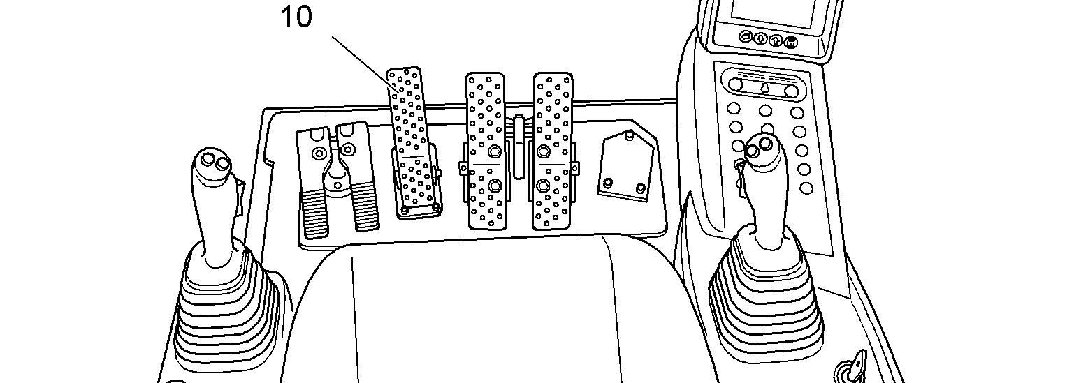
The positioning swing brake (optional)
The positioning swing brake is used for progressive and sensitive braking of the uppercarriage.
Note!
Increased wear.
Donotusethepositioningswingbrakepurelyasaservicebrake,butonlyasastop and parking brake.
Usingthisbraketostoptheuppercarriagerunningat thefull swingRPM isnot permissible since this would result in a quick abrasion of the brake discs.
In any case, first use thehydraulic brakingto greatly reduce thespeed of the uppercarriage
Depress the pedal 10 when the uppercarriage is near standstill
The uppercarriage canbestoppedprecisely and progressively in thedesired position.
3.4.2Attachment control
Operate the stick cylinder (left joystick)
The stick cylinder is operated using the left joystick 4
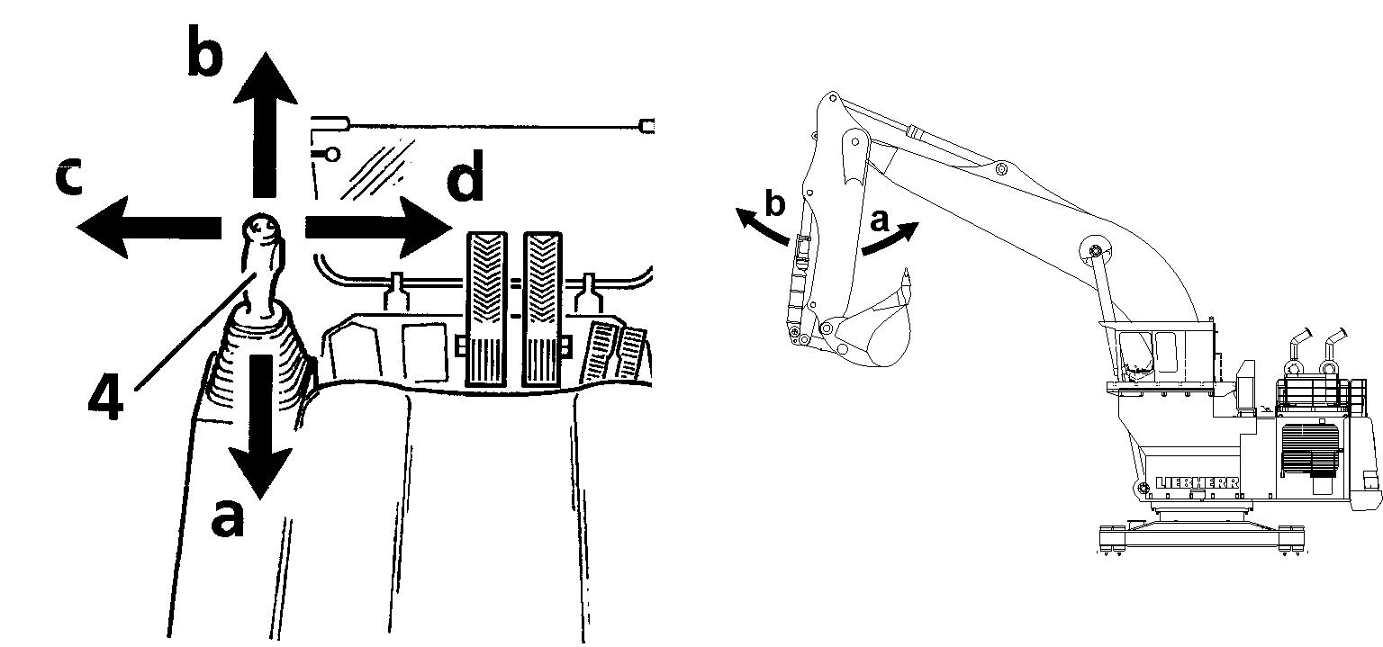
Push the joystick back a. Stick will be drawn in. Push the joystick forwards b Stick will be extended.
Operate the boom cylinder
The boom cylinder is operated using the right joystick 3
Push the joystick back h Attachment will be raised. Push the joystick forwards g Attachment will be lowered.
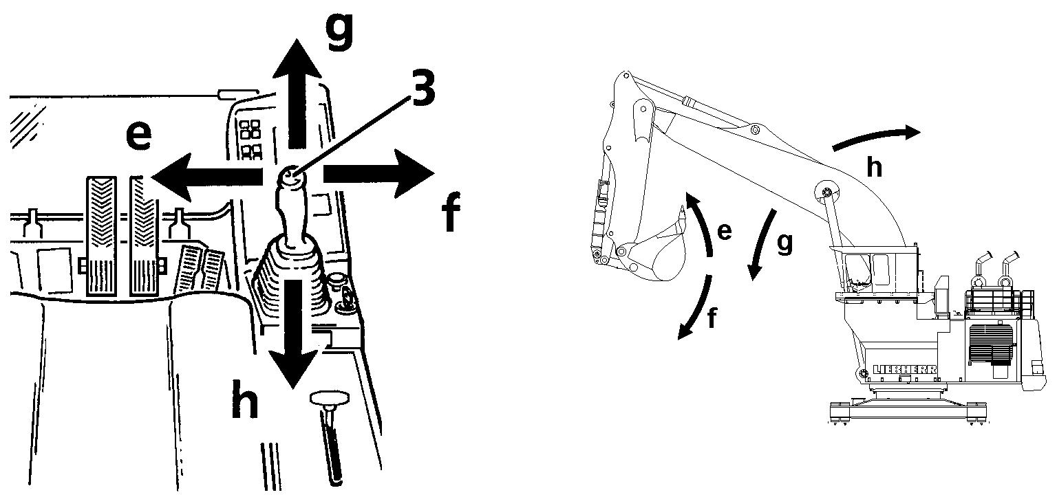
Operate the bucket
The bucket cylinder is operated using the right joystick 3.
3.4.3Overload warning device (Option) General
Theoverloadwarningdeviceshowsthemachineoperatorwhenthepermissibleload carrying capacity has been reached both optically, via the warning symbol and acoustically, via a buzzer.
The overload warning device is designed to prevent the permissible load torque beingexceededunintentionally.Inthisevent,theworkingradiuswillhavetobereduced or the load set down without enlarging the workingradius.
Theoverloadwarningdevicedoesnotrelievetheoperatoroftheresponsibilityoflifting loads which are either known or are permitted on the basis of the load carrying capacity of the machine.
Thepermissibleloadcarrying capacityisdependentontheconditionofthemachine and should be taken from the load chart in the cab.
The load carrying capacity values attain a maximum of 75% of the tipping capacity or 87% of the hydraulic lifting power in accordance with ISO 10567.
Note!
The load values are subject to change if attachment parts and work tools are attached or dismounted.
Alwaysrefertotheloadchart,andmakesurewhicharetheattachmentpartswhose weights are considered or not in the indications of the rated lift capacity chart.
Asanexample,iftheweightofthebucketisconsideredintheliftcapacitychartand the bucket is dismounted for the lifting works, then the lifting capacities can be increased by the weight of the bucket.
Inthesameway,ifthebuckettiltcylinder,theshiftingleverandtheconnectingrod aredismountedeventhoughttheirweightsareconsideredintheliftcapacitychart, then the indicatedliftingcapacitiescan be increased by the weights of these parts.
Withthespecifiedload,themachinecanberotatedfrom360°onevenandhorizontal ground.
Use the overload warning device
Danger!
When carrying out load hoisting work with the machine, the relevant accident prevention precautions are to be observed.
The overload warning device only gives theoverload information. It does not shut down the machine. Thus, loads lifting remains the responsibility of the operator.
Mode of operation
The overload warning device comprises two constant pressure switches which are connected to the boom and stick hydraulic cylinders. If the load pressure in the boom or in the stick hydraulic cylinders reaches the level of the shift pressure, the pressure switch emits a signal, the warning symbol shows on display and the buzzer sounds.
Start the overload warning device
Danger!
Noloadhoistingworkmaybecarriedoutiftheoverloadwarningdeviceisdefective. Have the overload warning device repaired by a professional.
Make sure that you obey all the precautions to prevent accidents. Checkthepermittedloadcapacityofthemachineontherelatedloadcharttable, which is located into the cabin.
Makesurethattheoverloadfunctionsworks:extendtheboomhydrauliccylinders to the stop. Then push the boom joystick to extend more the boom cylinders. The warning symbol must show on display. The buzzer must sound.
Caution!
Thisisonlyafunctionaltestofthewarningsystem(qualitativetest),butitdoesnot mean that the adjustment is correct.
Press switch S18 on keyboard. Overload warning device is activated. LED in switch comes on.
If the machine gets its maximum load capacity: The warning symbol shows on display. The buzzer sounds.
Stop the movement immediately.
When you switch off the machine, the state of the overload device is recorded and will be the same at the next start.
Deactivate the overload warning device
Note!
For work using a bucket, deactivate the overloadwarning device, since the increased effort of the machine will cause the overload warning device to be permanently active.
Press switch S18 again. Confirm by pushing button S349 on the display. Overload warning device is activated. LED in switch S18 goes out.
3.5General working methods
3.5.1Minimum impact working methods for your machine
Toincreasethe servicelife of themachine andavoidunnecessary damage andthe resulting repairs, please note the following points: stopping the equipment on the walls of the ditch. the equipment is knocked against the materialtoberemoved,inthelongitudinaldirectiontoo,isnotpermitted.Repeatedly hitting the work equipment against rock or other hard material will damage steel parts and machine components. chionandwork tool,the work toolcould hit or break through into the cab. This could damage the cab and injure the ma- in rocky material. This will extend the work cycles and could result in damage to the bucket and other machine components. l partner if special teeth are required for heavy or special applications. thisshouldoccur,slowlylowerthemachineto the ground. Do not permit the machine tolower quickly and do not intercept the falling movement using the hydraulics,since this couldresultin damage to the machine.
3.5.2Preparatory activities
Danger!
Risk of fatal injury and damage to the machine when working. erating instructions.
Danger!
Risk of fatal injury due to rotating the machine. Ensure that nobody stands within the hazard area r of the machine.
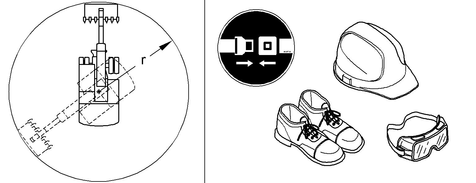
Caution!
Risk of injury when working.
Always wear safety shoes and, particularly when leaving the cab when demolition work is going on, a protective helmet and safety glasses. Always wear the seat belt. Use the horn to give a short warning signal before starting work.
3.5.3Hoisting work
Hoisting work is understood as being lifting, transporting and unloading loads using a securing method (rope, chain etc.) and where personnel are required to assist in securingandunloadingtheload.Thisincludes,forexample,theliftingandunloading of pipes, shaft-top supporting rings or containers.
Danger!
Themachinemay onlybeoperatedforhoistingwork if theprescribedsafety devices are present and functioning correctly.
Machinesusedforhoistingworkmustbeequippedwiththefollowingsafetydevices, in accordance with European standard EN 474-5:
Load take-up device for safe securing of a load (optional extra)
Safe take-up devices include for example lifting hooks which are mounted in place of the bucket. Lifting hooks can also be replaced with safety hooks welded to the bucket (to be approved by Liebherr).
Overload warning device (optional extra)
Theoverloadwarningdevicemustalertthemachineoperator visuallyor acoustically if the permitted load value according to the load chart has been reached or exceeded.
Hose rupture protection on the hoist cylinders (optional extra)
Thehoseruptureprotectionmustcorrespondwiththerequirementsof ISO8643. Load chart inside the cab
Ifthepointsreferredtoabovearenotorareonlypartiallyfulfilled,themachine may not be used for hoisting work.
Attaching and removing attachment parts safely have general approval from Liebherr for installationor attachment may not be installed or attached to th propriate technical documentation necessary forthis purpose. of theapprovedworkingtool andof related approved devices. chine on level, firm ground. ment if it is not safely positioned on the ground or supported with appropriate supports. s,youmuststoretheequipment,switch off the engine and press the start key to the contact position and both joysticks draulic system. parts.Usedeviceswhicharesuitablefor thispurpose and which have sufficient load carrying capacity. pacity. Wear work gloves when working with wire cables. tiltedup.Neveruseyourfingerstolocatebores;usethecorrectpunchfortheprocedure. aulic lines are secured correctly and that all bolts and connections are tight. the hydraulic circuit to stop dirt entering. Only allow authorized persons in the vicinity of the machine or the lifting device used.
Removing and installing attachment pinssafely hole conductor held by another person must be used. the bolt's threaded hole and only hammer these screws. meansofcastlenutsandcotterpins,firstdrivethe bolt tothestop,thenscrewthecastlenutby handuntilcontactandthen onlypull it far enough to push in the cotter pin.
3.6Transport tion. an inclination of the angle value indicated in the "Technical data" section of this manual (machine must be able to walk up unaided) and should have a wooden cover to prevent sliding back. any snow, ice and mud from the crawler / wheels of the machine. pedals. chine operator the required signal. trollingbackwhenthemachineisdriving up onto the flatbed. hold the attachment securely over the loading area, drive very carefully up the ramp and onto the transportation vehicle. restrictions during transport on hoe attachment, tilt the arm in and dismantle the bucket during transportation. trailer,theupperstructuremustbesecured facing the undercarriage using the stop bolts (only A devices). ing individual parts using chains and blocks to prevent slipping. ignition key and tilt up the safety lever. about the route to be travelled, particularly as they relate to width, height and weight restrictions. through tunnels. itwasloaded.Removeallchainsandblocks.Starttheengineaspertheoperating instructions.Drive carefully offthetraile the workingattachment as securely as possibleover the groundwhiledoingthis. Have a spotter guide you.
Transporting the machine safely ons, use only suitable means of transport and lifting devices with sufficient load-carrying capacity.
3.6.1Excavator lifting and lashing operations
Danger!
For safety reasons, always consider the precautions given in this section.
Lifting precautions
Lift element: spondingtransport drawing, s of other kind (cables, chains, slings) if necessary, es in accordance with the regulations, respecting the angles given on the sticker for lifting and lashing operations (refer to the description below).
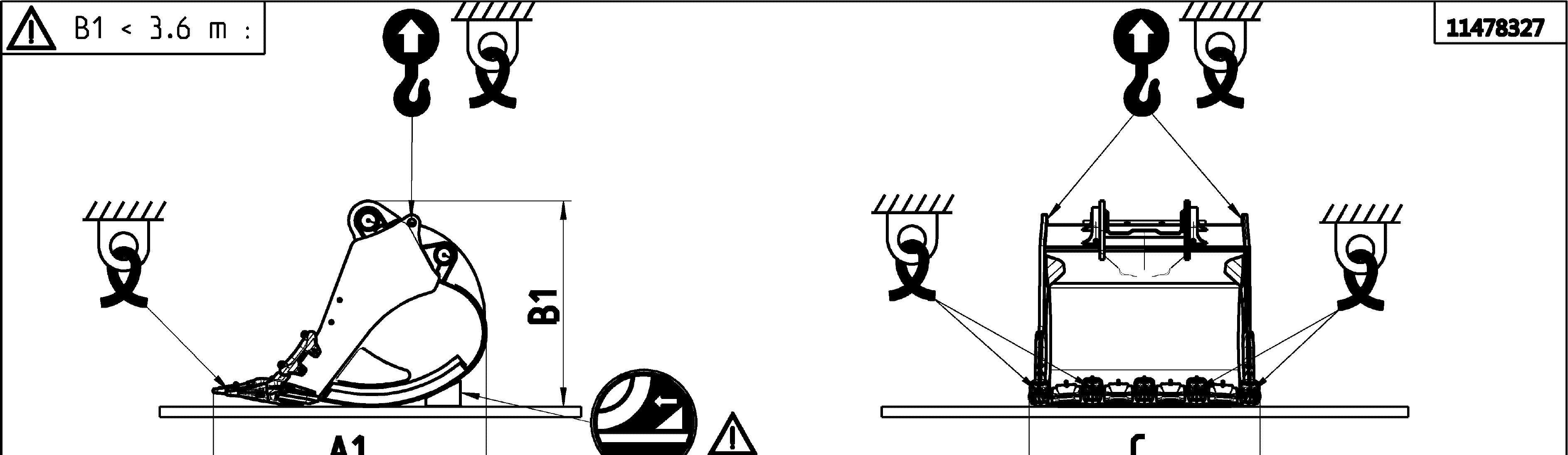
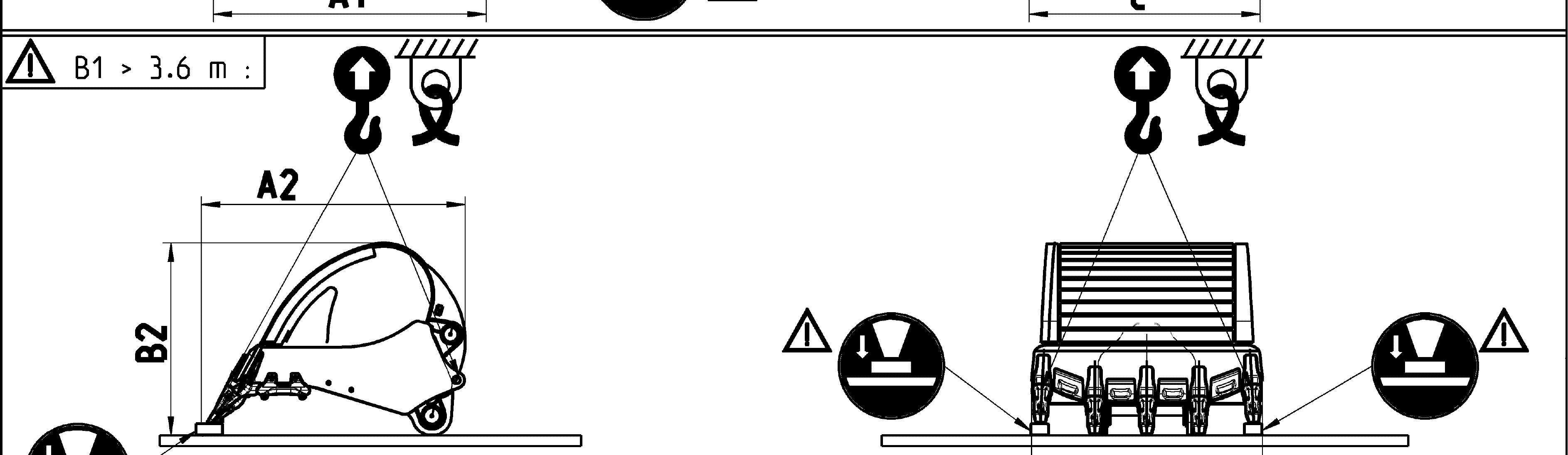
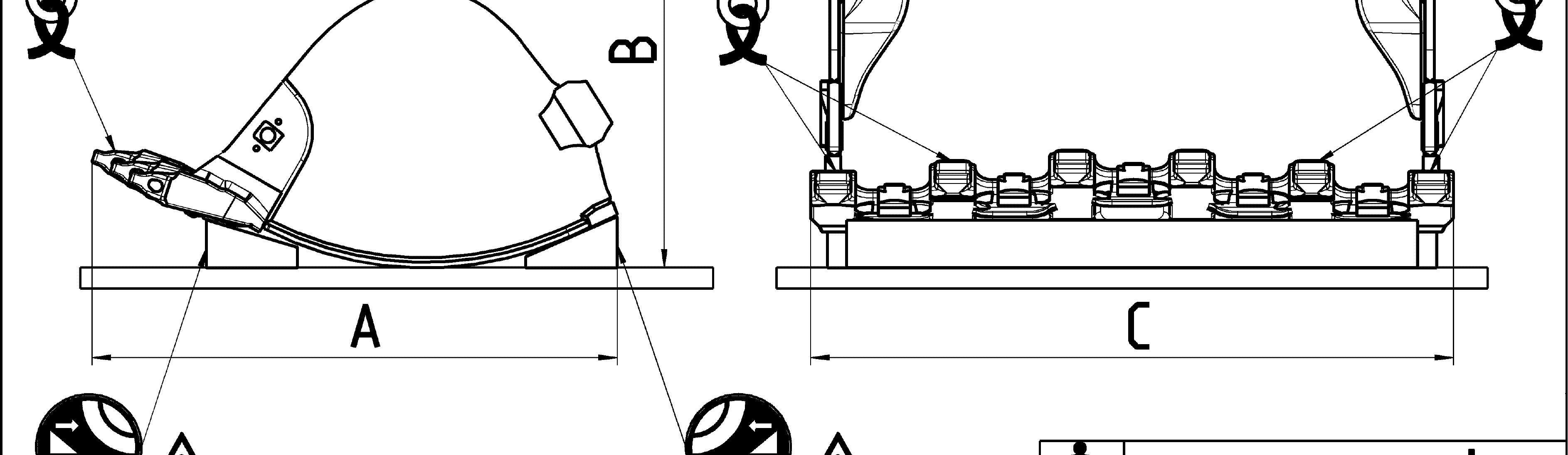
Additional lifting precautionsfor backhoe buckets
When you lift the backhoe bucket, also obey the precautions that follow: the stickers placed on the bucket.
e center of gravity of the bucket. transport position as shown in the transport drawing. 6 m, turn over the bucket safely.
Additional lifting precautionsfor shovel buckets
When you lift the shovel bucket, also obey the precautions that follow: the stickers placed on the bucket.
Lashing precautions
e center of gravity of the bucket.
Lash element: in order to ensure safe lashing, sponding transport drawing, respecting the angles given on the sticker for lifting and lashing operations (refer to the description below), supporting surface so as to avoid element to slip (e.g. using wooden parts, nonslip mats...), friction is guaranteed by manufacturer certificates, tween the load and the support, between the support and the flatbed trailer), carried are free of dirt, ice, snow, oil and grease.
Additional lashing precautions for backhoe buckets
When you lash the backhoe bucket, also obey the precautions that follow: the stickers placed on the bucket.
he center of gravity of the bucket.
tions. The height B1 gives the correct transport position as shown in the transport drawing.
Additional lashing precautions for shovel buckets
When you lash the shovel bucket, also obey the precautions that follow: he center of gravity of the bucket.
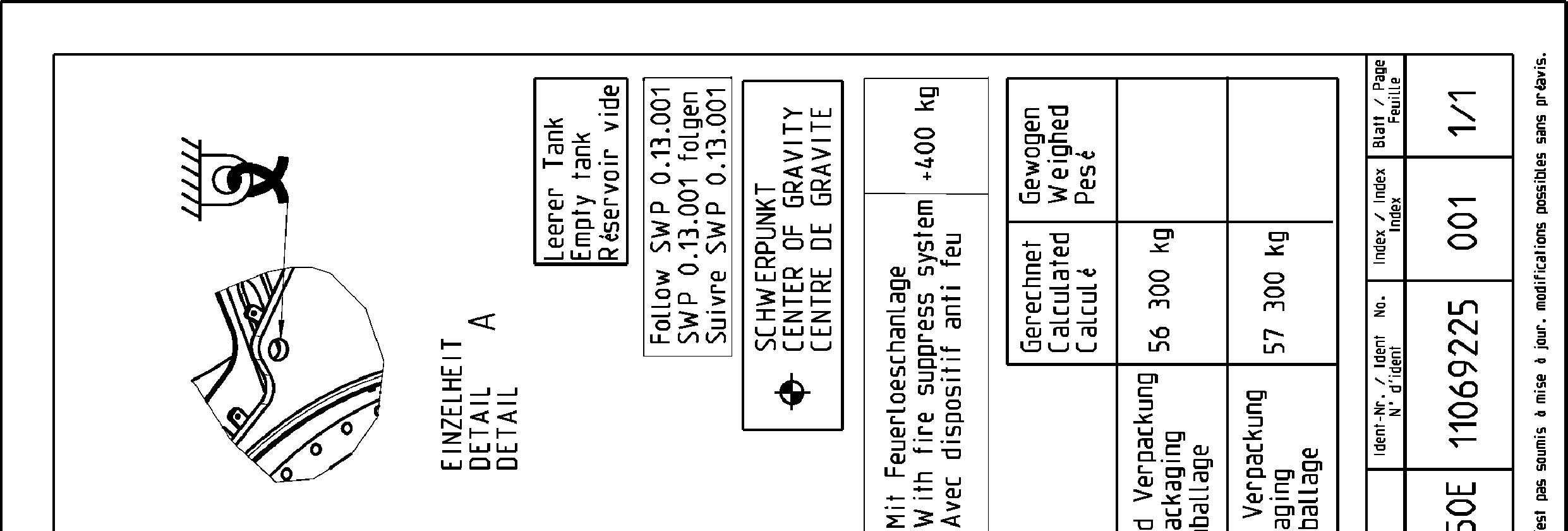
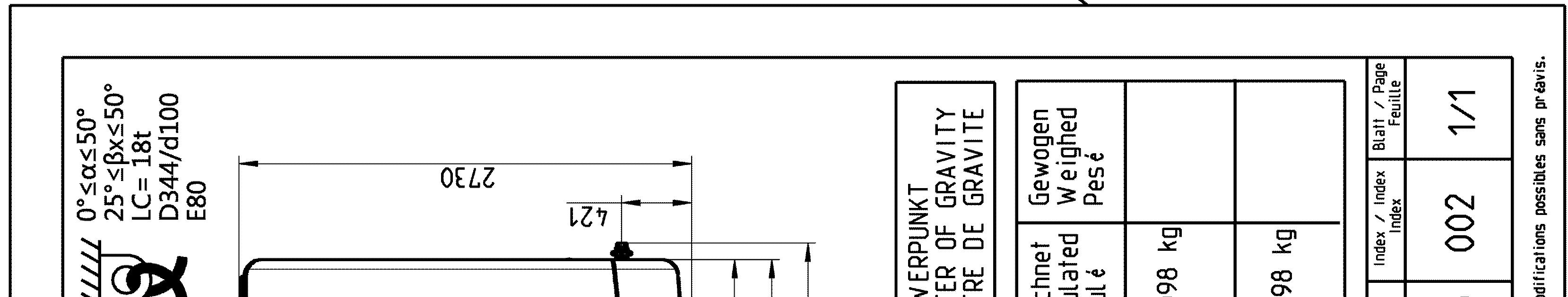
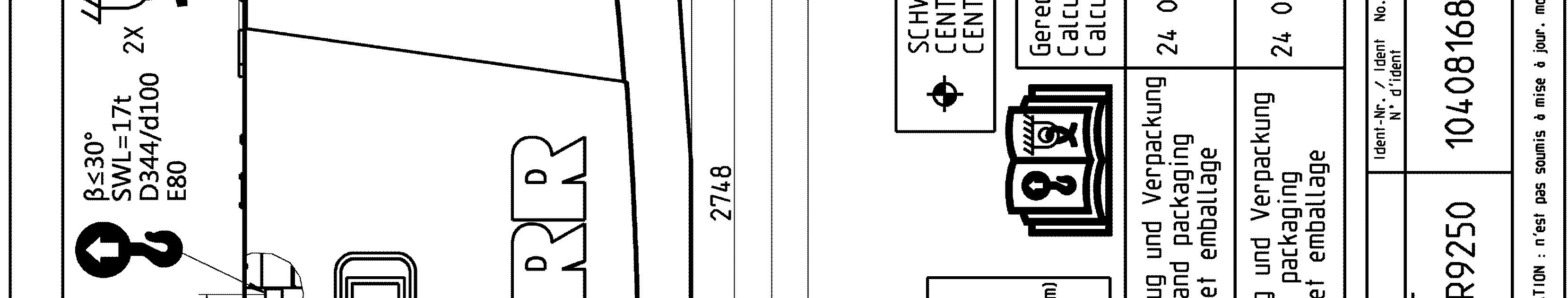
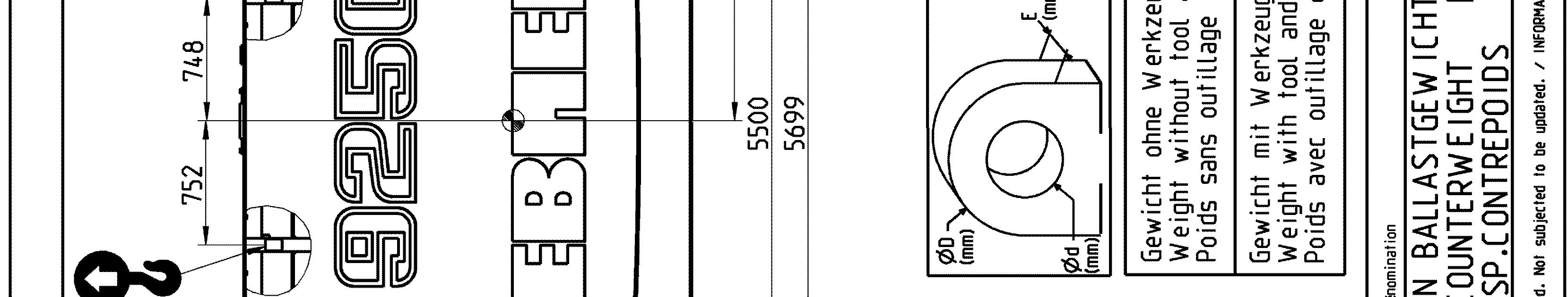
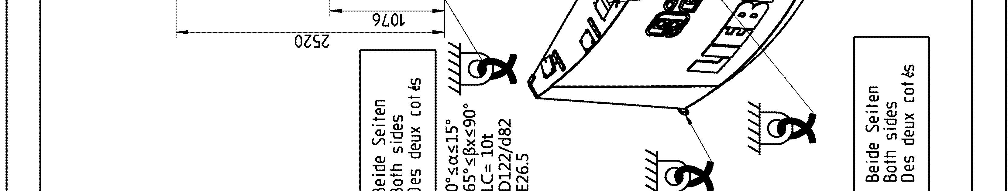
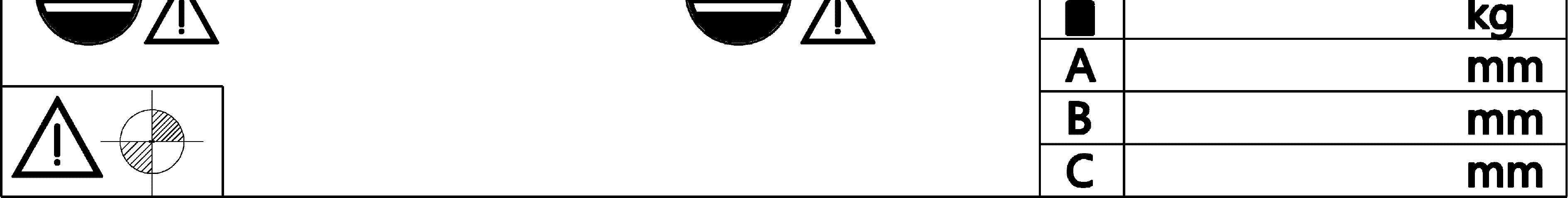
Sticker for lifting and lashing operations
Thefollowingstickerisplacednexttoeachtransportdrawingontherelatedpartand package. It shows rules and precautions which you must obey for transport operations.
Fig.
Sticker for lifting and lashing operations
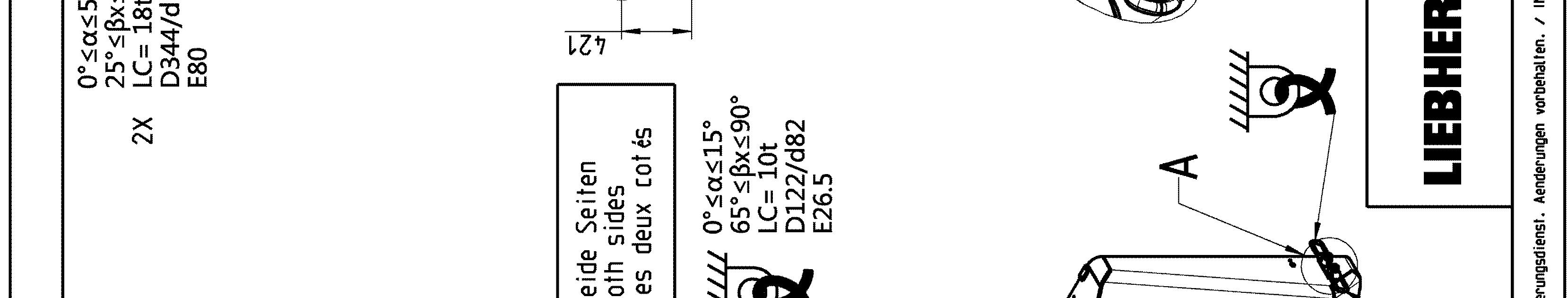
The Lashing Capacity LC is the maximum force that the lashing ring can hold in accordance with the angles given on the transport drawing.
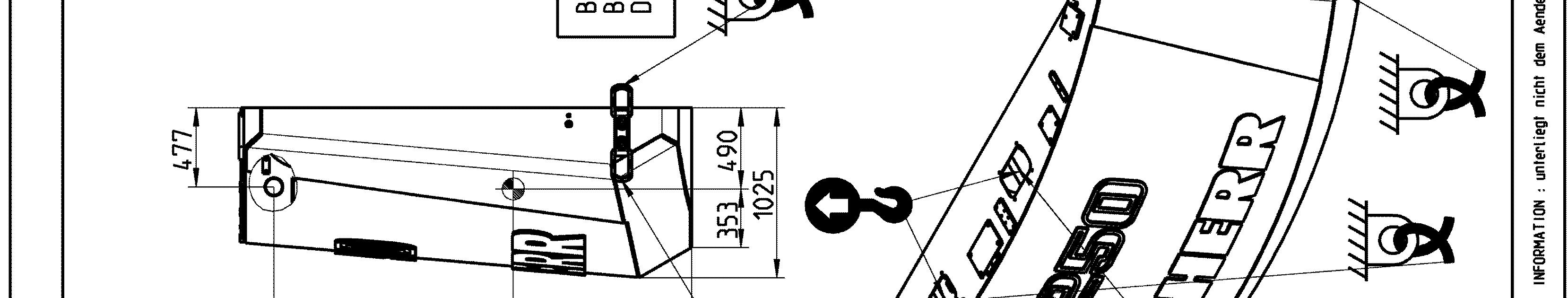
TheSafeWorkingLoadSWL isthemaximumloadthattheliftingringcanholdinaccordance with the angles given on the transport drawing.
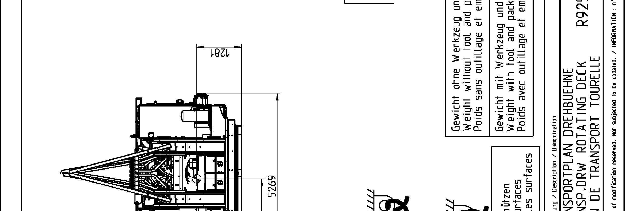
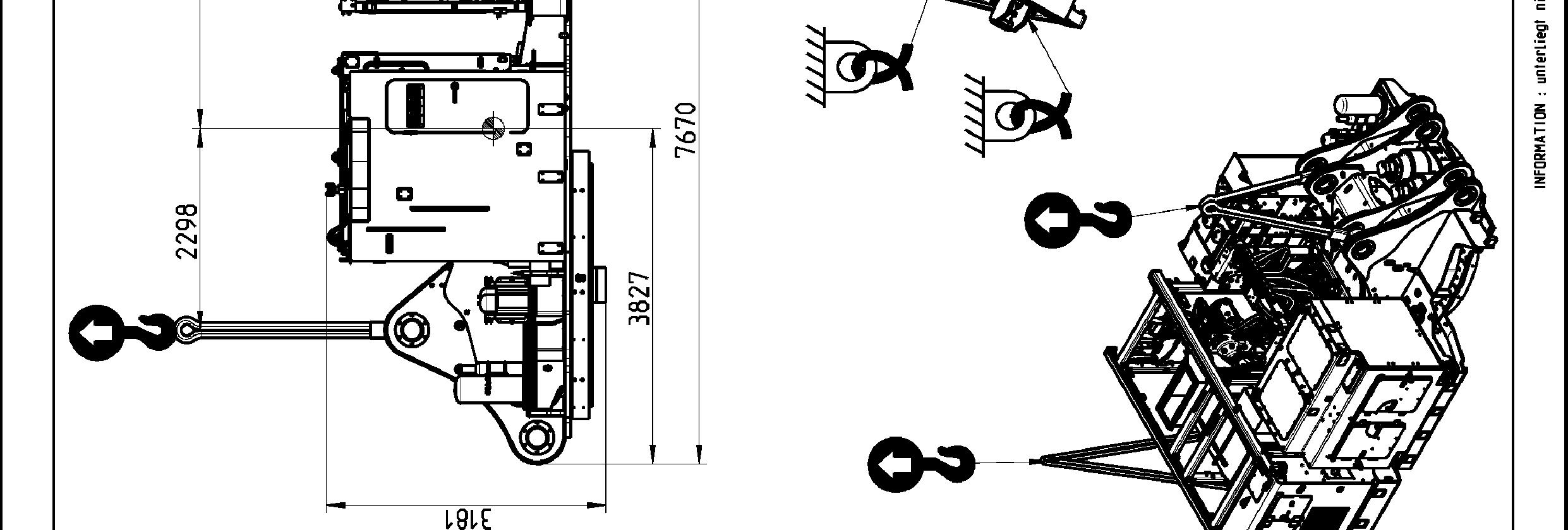
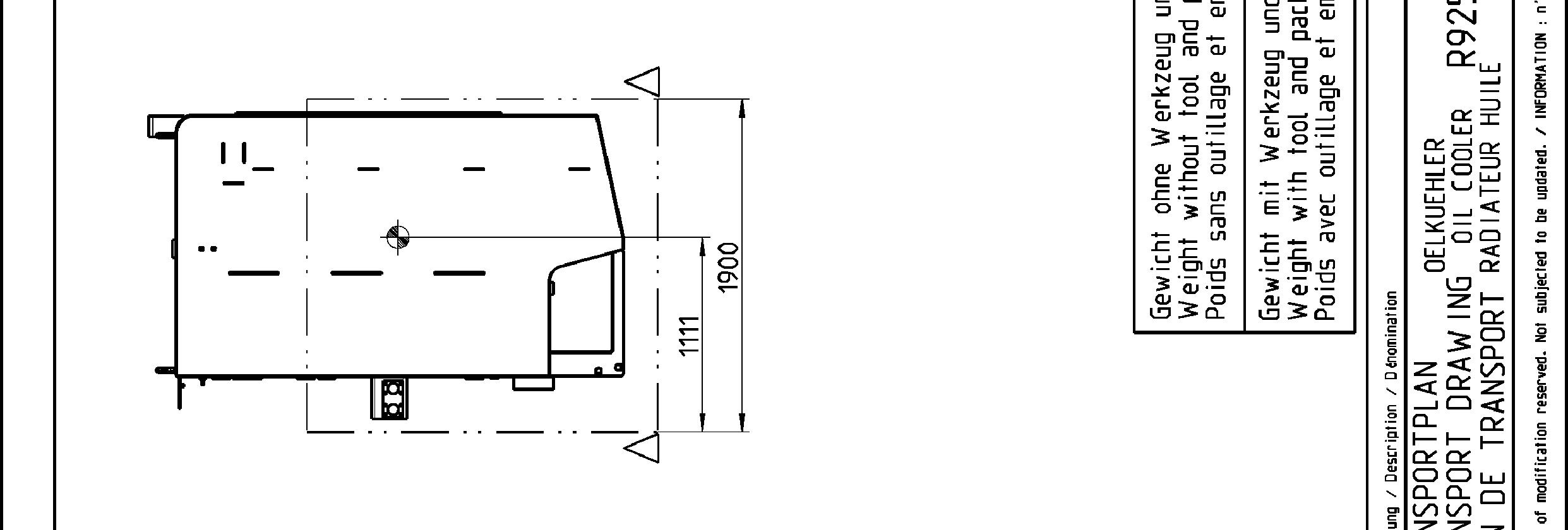
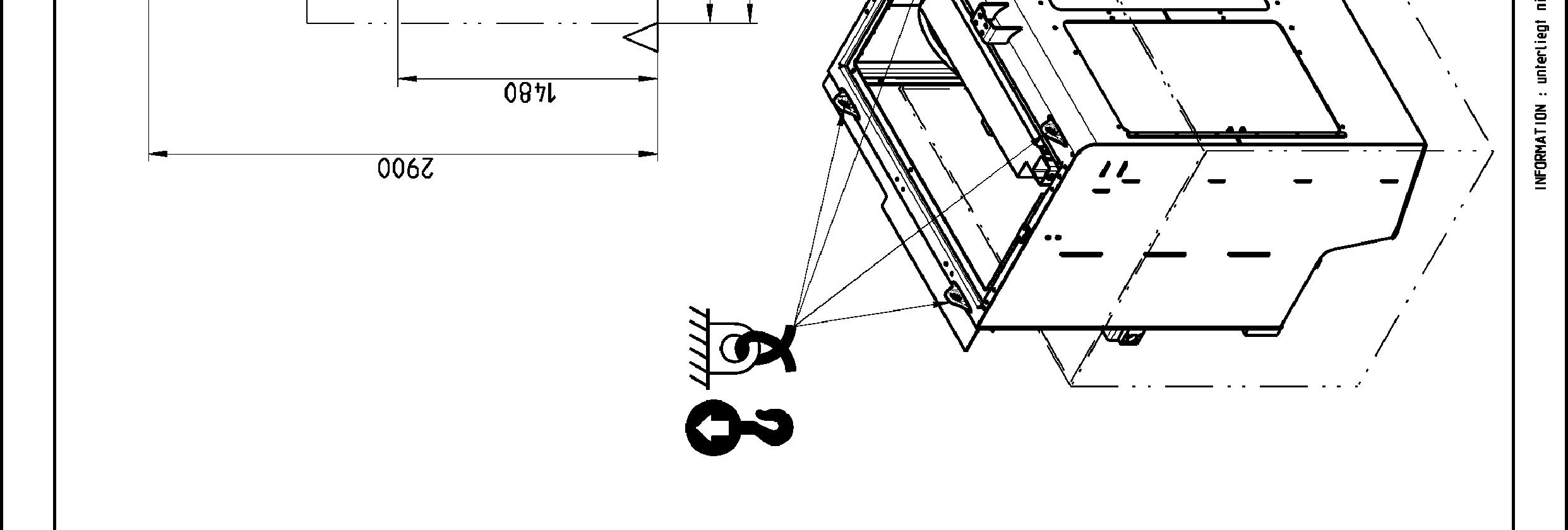
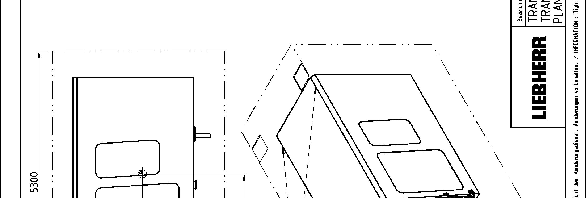
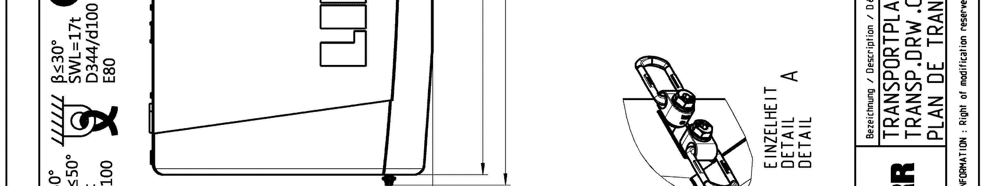
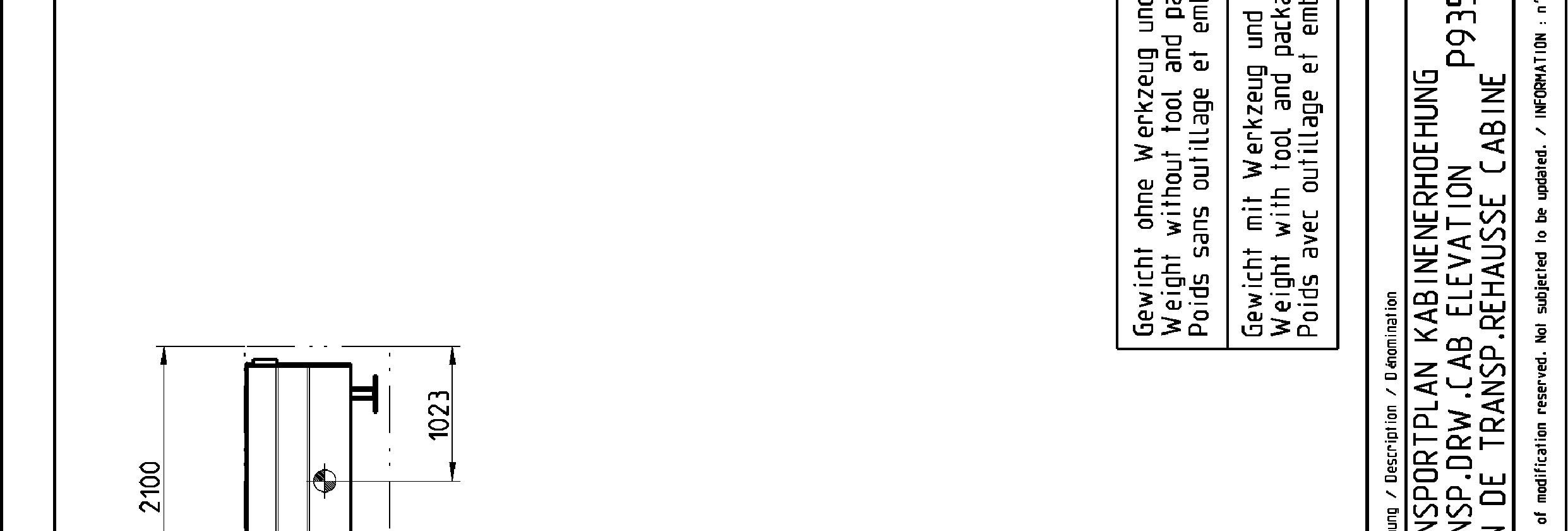
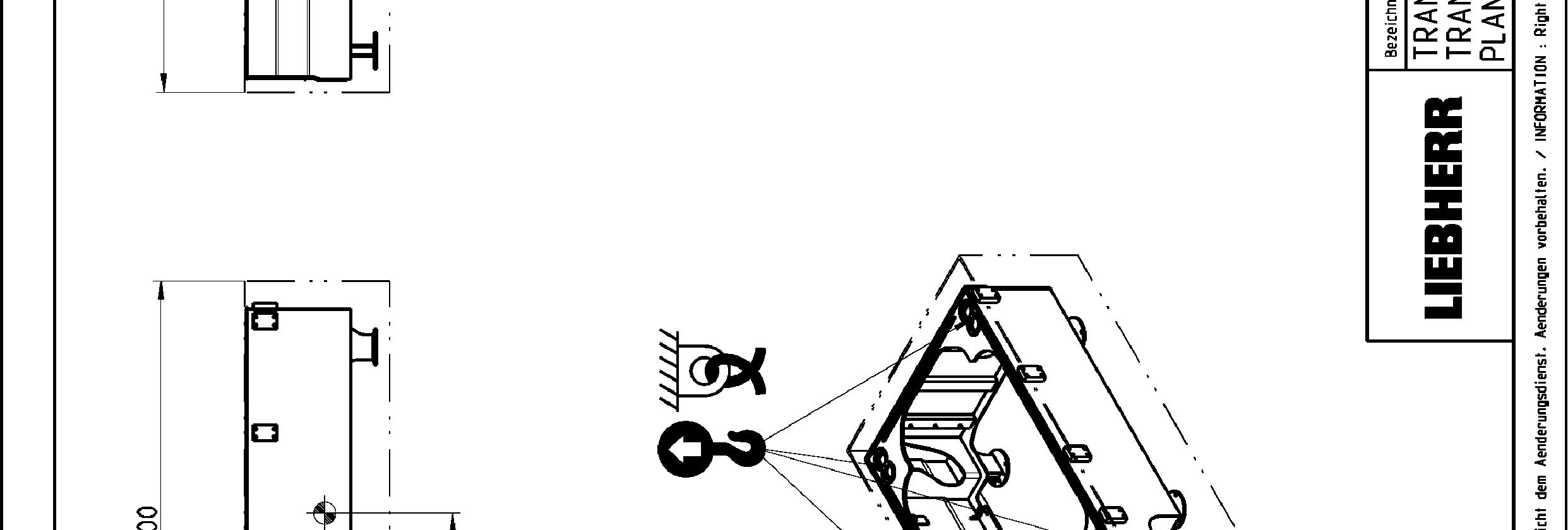
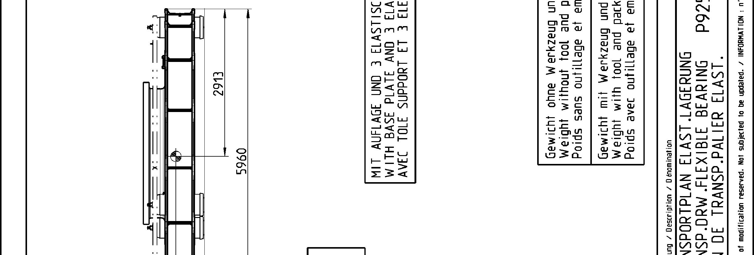
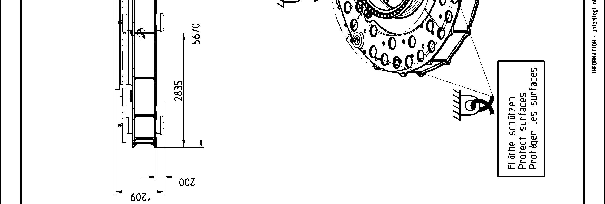
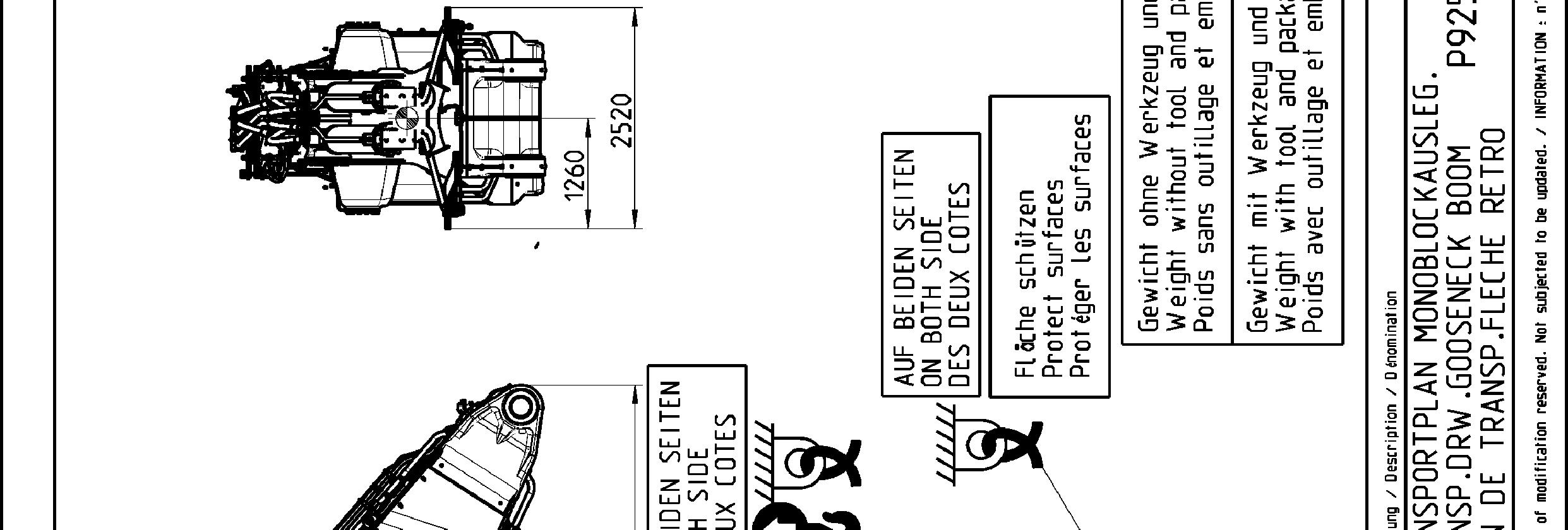
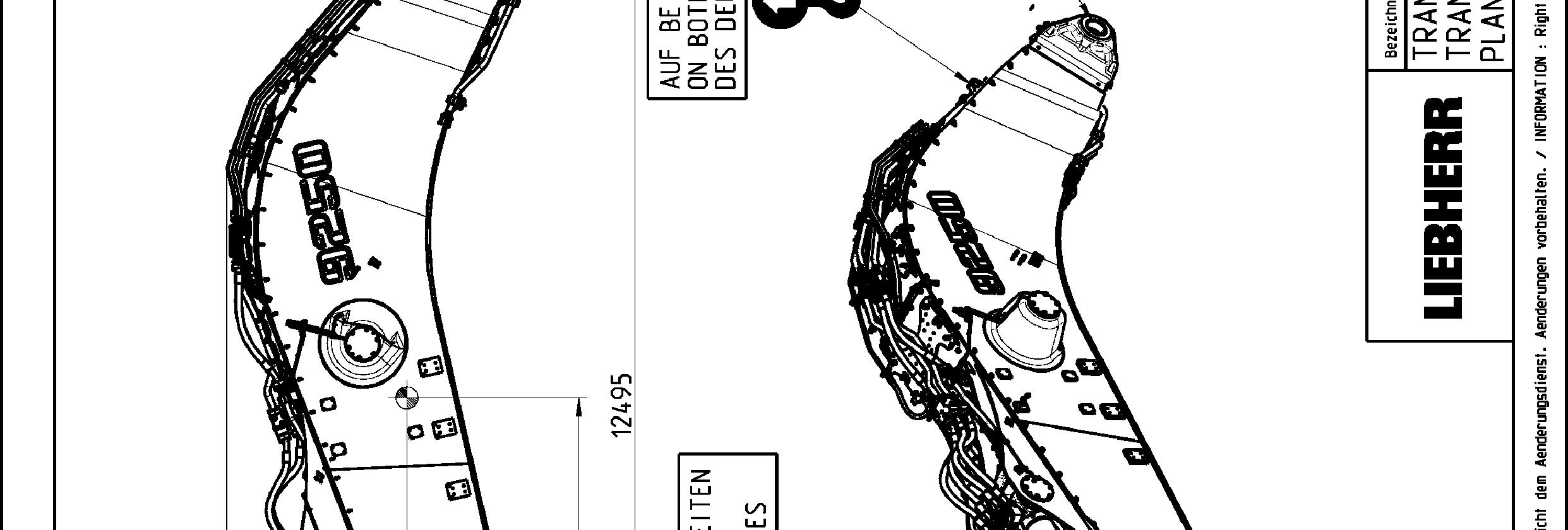
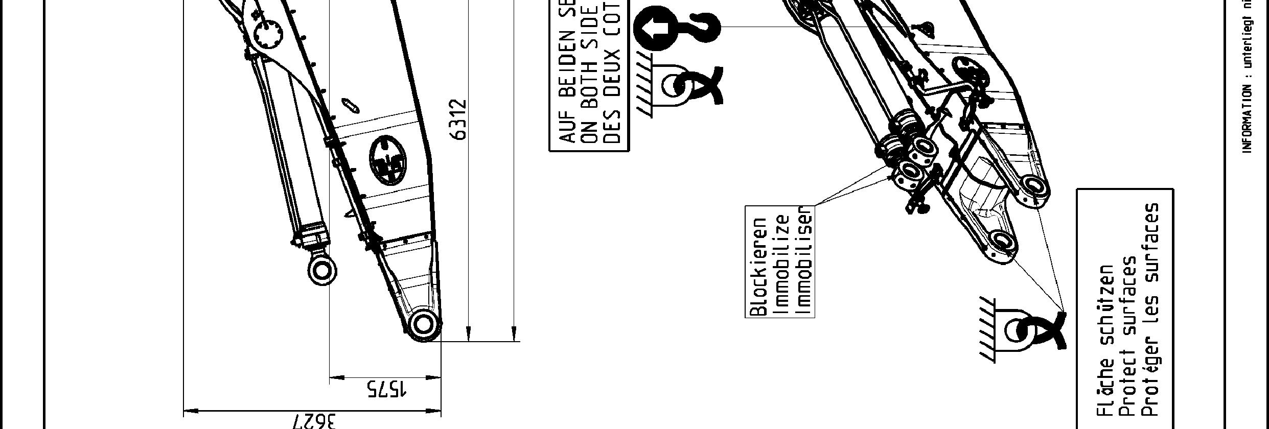
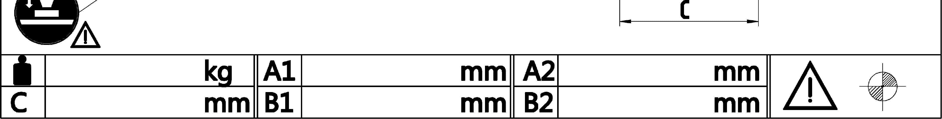
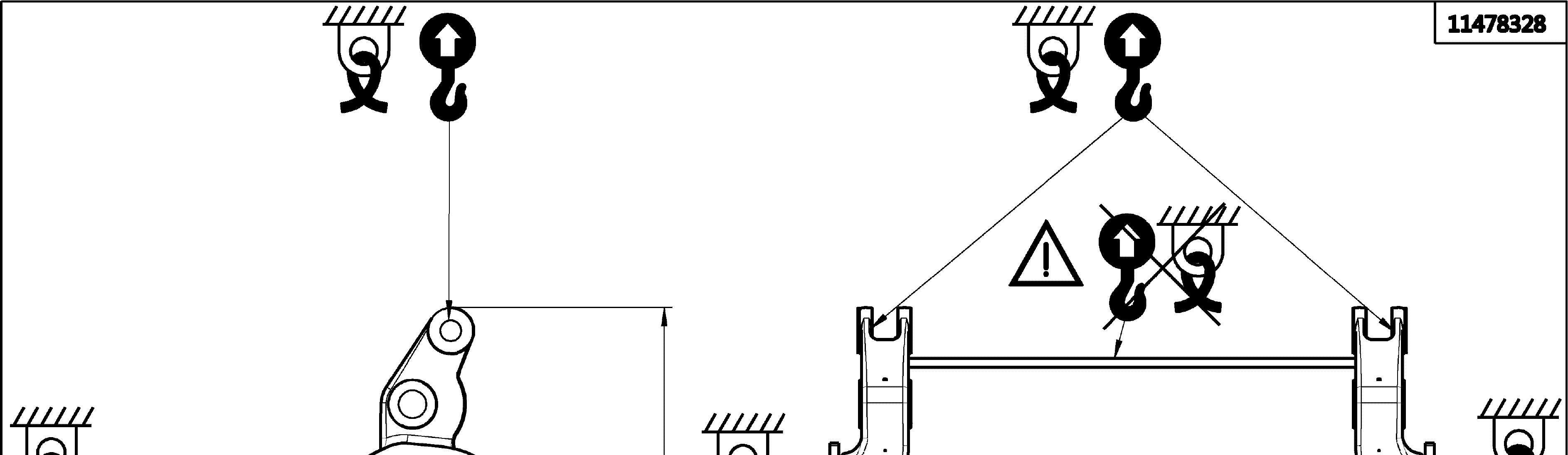
Transport drawings
The following drawings indicate the different lashing and lifting points on the elements of the excavator. Weight (with and without transport tooling and packaging), overall dimensions as well as centerof gravity are also given.
Theaimofthesedrawingsistoensuresafeoperationduringtransport,handlingand storage.
Note!
Thelashing andliftingpoints areindicated onthe concernedelementsof the excavator by specific labels (see § "Signs on the machine"). To be easily recognized, lifting points are painted in yellow (in red if excavator is yellow) as well.
Danger!
Theliftingpointsgivenonatransportdrawingforanelementaredesignedtoliftthis element only and nothing else.
Never lift an assembly of several elements by the lifting points of only one of these elements.