62 minute read
system


5.14.1Low and high voltage circuit
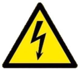
Danger!
For any maintenance or repairnearthe LOW andHIGH VOLTAGE circuit,personnelhavetobecertifiedandqualifiedaccordingtotheircompetencesandauthorized bytheir employer to work on anelectrical installation. Current practices have to respect local safety regulations for electrical installations (wear of adapted PPE, works on electrical installation, lockout procedures, etc...).
Always use adapted tools for the voltage.
Any work or maintenance on the LOW and HIGH VOLTAGE circuit or boxes must be done with power totally disconnected and the concerned electrical circuit must be locked out according to local regulations by the electrician.
For any repair for a fault with HIGH VOLTAGE > 1000V, the excavator must be completelydisconnectedfromthenetwork.Onlyelectricalpersonnelareallowedto operate according to local regulations.
ForanyrepairforafaultwithLOWVOLTAGE<1000Vtill24V,minimumapproach distanceforanyconductiveobjectmustbeobserved.Forlowtensionelectricalcabinetandrepairwithpowerswitchedon,electricalpersonnelareunderobligationto disconnect any accessible conductive object and to border the working area with banner, safety nets, fences, etc...
5.14.2Standby heating supply
By pushing the button S184 («Control OFF») inside the cabin or any emergency switch, main breaker Q2A in high voltage electrical box S1 will open. High voltage stillsuppliesS1transformerT5Mforanti-condensationheatersandfor-40°Cheating system (optional).
Danger!
Standbysupplypresenceonmachine.Beforeanymaintenanceorworkonelectric HV/LV installation, the electric supply of the machine must be totally locked out at field switch.
Standard lockout procedure to disconnect totally the excavator: Locate power station supply and distribution. Stop excavator, disconnect excavator from the network at field switch. Check voltage presence on excavator supply line. Earth and short-cut the supply line. Lockout and tag out at field switch. Identify (i.e. check that ignition of Open S1. Open Q1A manual switchand use red lever to earth the uppercarriage. Close S1 and keep key in a safe place.
5.14.324V circuit
To ensure trouble free operation of the excavator, the electrical system must be in good condition. The gauges, indicators and components of the electrical system should be checked regularly for proper function (refer to «Control and maintenance chart»).
Always replace burnt out fuses and bulbs. Do not repair fuses. Check for bare and damaged wires, whichcould cause damage to the electrical system or a fire. Check for loose, dirty or corroded connections.
5.14.4Notes on the electrical system
Danger!
Risk of injury due to formation of sparks. Avoidsparksandnakedflamewhenchargingbatteriesorworkingonthebatteries.
Always wear protective goggles and gloves.
Burnt-outfusesandbulbsshouldbereplacedimmediatelywhenthecauseofthe defect has been corrected.
Correct defects such as loose connections, abraded cables or badly fastened clamps immediately.
Disconnectthebatterieswhen workingontheelectricalsystem orwhencarrying out electric arc welding on the machine.
Danger!
Risk of injury due to formation of sparks. Disconnect the negative terminal (-) first and connect it last.
5.14.5Main battery switch
Caution!
Take particular care with machines with built-in independent heating. Only switch off the main battery switch is over.
5-51 Main battery switch
Before starting any work on the electrical system, including welding work on the machine, switch the main battery switch to position 0
Whenwashingthemachine,covertheelectricalunits(particularlythegenerator, cabling, electronic components and measured value sensor) to prevent water penetrating.
Note!
Batteries can become flat if the machine is out of service for longer periods. Beforelayingupthemachine forlongerperiods,switchthemainbattery switch to position 0 (off).
5.14.6Battery care
Thebatteriesmustalways bekeptcleantoensurethattheyareabletofunction perfectly.
Particularcareshouldbetakentocleanthepoleendsandcableterminals A regularlyandtothencoverthemwithathicklayerofacidproofgrease(seeFig.5-52).
Danger!
Bent rubber hoses on the central gas outlet increasethe risk of explosion! Thehydrogencontainedinthebatteriesshouldnotbeallowedtobuildupintheaccumulator box and must be able to escape via the rubber hoses. The central gas outlet hoses must be routed without kinks.
Check the condition of the hoses regularly, particularly after installing a battery (see Fig. 5-52).
The fluid level in the cells should be 10 to 15 mm above the top of the plate. Only distilled water must be used for any refilling.
5-52 Battery care
From time to time, measure the acid concentration C using an acid tester. When the battery is fully charged, the unit weight is 1.28 kg/l (31.5°Bé).
Ifthe acid tester displaysa lower value,thebatteries arevirtually flat and should be charged if necessary.
5.14.7Electrical components location
5.14.8Electrical boxes and cab pressurization
The aeration devices are installed as follows:
The air filters for electrical boxes and cab pressurization must be cleaned regularly. Clean the air filters: Press to open the dust discharge valve 5. Replace the main element and the safety element of the air filter system. For maintenance intervals, refer to the «Control and maintenance chart».
5.15Heating/air-conditioning system
The excavator has a heating and an air conditioning system as standard. The heating system operates with a heater under the cab floor. The air conditioning system has the elements that follow:
Note!
Incaseofrepairatcondenserorreceiver,therefrigerantmustberemovedandcollected in an applicable tank The collectedrefrigerant can be cleaned and re-prepared by refrigerant manufacturers.
For maintenance intervals, refer to the «Control and maintenance chart».
5.15.1Heating system
Iffiltersaredirty,theairflowinbothheatingandairconditioningsystemsisreduced. This results in the forming of frost and system shut-off.
Removeandcleantheheatexchanger2andthefreshairfilter3atintervalsspecified in the «Control and maintenance chart».
Do not operate the machine, even briefly, without the filters 3 because, in this case, the heat exchanger 2 will quickly become blocked.
Clean and change the fresh air filter: Remove the fresh air filter 3
Note!
Never wash the filter elements with hot water or a steam jet. Never wash the filter elements with acids or aggressive solvents. If damaged or in a bad condition, replace the filter elements.
Clean the filter elements.
The container which is filled with the coolantmixturefor theheater is installed in the cab elevation.
Fill the container with coolant mixture: Remove the filler cap 1 to add coolant mixture. Forcoolantmixturespecificationsandquantity,refertosection«Operatingmaterial chart».
The heating system has also a preheating unit installed in the cab elevation which makes the coolant mixture warm.
No maintenance is necessary for the preheating unit. Butiftheheatingsystemisstoppedforalongtime,makesurethatthepreheating unit (with pump) stays always filled with coolant mixture or preservative fluid.

5.15.2Air-conditioning system
Switch on the air conditioning system for approximately 10 minutes every 2 or 3 weeks, regardless of the season.
During the warm season, perform checks or maintenance works that follow:
Filter check:
Check and clean the recirculated air filter 2 located in the roof of the cab.
Air conditioning unit check:
Check condition of receiver 5 and filter/dryer 6
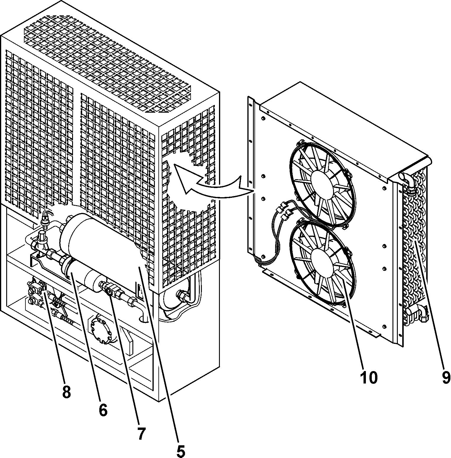
If there is corrosion, rust or mechanical damage formation on the receiver 5 (on mountingconsoles,connectingparts,...),itmustbereplacedimmediatelybyreasonsofexplosions.Whilereplacing,takecareofthemountingdirection.Theexit is marked with an "A" and the top side is marked with "OBEN".
Replacethefilter/dryer6atregularintervals,atleastonceayear.Itmustbealso replaced after each opening of the refrigerant circuit. The arrow symbols on the filter/dryer must be in the direction of the expansion valve.
Inaddition,therefrigerantchargeofthesystemmustbecheckedatregularintervals,byobservingthesightglass7whiletheairconditionerisoperating.Bubbles or foam in the sight glass 7 indicate an insufficient refrigerant charge.
In this case, the system must be checked and refilled by a trained specialist. Checkthecolouroftheindicatorinthesightglass7.Iftheindicatorbecomesyellow,itmeansthatthereistoomuchhumidityinthesystem.Replacethefilter/dryer 6 immediately by a trained specialist.
Checkmounting bolts fortightness
Check condition of fans 10 and replace if necessary (defective fan). The fans must be free of dirt and damages.
Check the condenser battery 9. If necessary blow it out with pressurised air or steam, from the inner side (fan side) to the outside.
Check for possible damages on the compressor 8
Check compressor fastening.
Check condition, alignment and tension of V-belt.
5.15.3Additional maintenance operations
Check operation of evaporator blowers and condenser fans. All blowers have to be in working order in order to avoid air short circuit.
Check electric installation.
Check all hose fittings and couplings for leakage.
Check setting and function of defrosting thermostat at the evaporator coil. Checkcompressorpressureswitch.Ifthepressureatthecompressoronthelow pressure side is too high, the compressor pressure switch lights up an indicator lamps. This means that the compressor is not working well.
5.16Check mounting bolts for tightness
The mounting bolts listed below must be regularly checked and re-tightened if necessary.
Refer to «Control and maintenance chart» for checks intervals.
Note!
WheninstallingboltsofsizebiggerthanM40thethreadofthescrewmustbeslightlycoatedwithaMoS2basedgrease.Alsogreasetheboltheadsupportingsurface, unless hereafter otherwise specified.
Danger!
Due to their size, most of the below listed mounting bolts require, to be tensioned totheprescribedtorque,theuseofaspecial,hydraulicorelectricactuatedtensioning device.
Thesehightorquetensioningdevices are power tools,whichmust beoperatedby trainedmechanics,knowingthesafetyprecautionsedictedbythetoolmanufacturer and that must be observed to avoid accidents or personal injury.
Inparticular,payattentiontochoseasolidandsecurereactionpointforthetooland position the reaction arm during operation. Keep clear of the reaction arm during operation; if it must be held or steadedduring operation, use alternative means of securing the tool during operation.
Caution!
The mounting bolts of the main components (especially the bolts listed below), of thehydraulichosesandofthecounterweightmustbereplacedaftereveryremoval.
Checkmountingbolts for tightness
5.16.1Mounting bolts of the counterweight
The eight mounting bolts 5 (M42) must be torqued to 4810 Nm.
Note!
Greasetheheadandthreadof thescrew andthetwosidesof the washerwithMo-
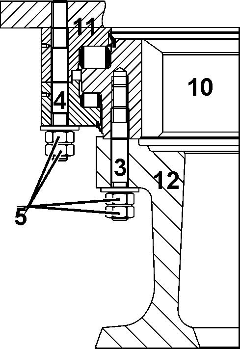
5.16.2Threaded studs of the swing ring
The threaded studs 4 (M36) for the mounting of the swing ring 10 to the uppercarriage 11 must be tensioned to 707,5 kN.
The threaded studs 3 (M36) for the mounting of the swing ring 10 to the undercarriage 12 must be tensioned to 707,5 kN.
Torque the lock nuts 5 on the studs 3 and 4 to 600 ± 100 Nm.
To get the correct stud tension, you must use the special tensioning procedure and tool (LIEBHERR recommends that you use the special tensioning cylinder ID. 5617448 at the required hydraulic pressure of 1350 bar, or that you use the tool ID. 10444128 at the required pressure of 1500 bar).
Danger!
Thespecialtoolmustonlybeoperatedbyqualifiedpersonnel,especiallytrainedfor the use of this high pressure tensioning device and aware of the operating instructionsaswelloftherecommendationsforaccidentanddamagepreventionconcerning this tool.
Useappropriateworkingplatformsandliftingdevicesto install andhold inposition the special tool while tensioning the studs.
5.16.3Mounting boltsof hydraulic tank
5.16.4Mounting bolts of Powerpack
Refer to section «Electric motor», in this chapter.
Checkmountingbolts for tightness
5.16.5Mounting bolts of the swing gear and motor
The mounting bolts 7 (M30) of the swing gear must be torqued to 1900 Nm. The mounting bolts 8 (M24) of the swing motor must be torqued to 960 Nm.
5.16.6Mounting bolts of hydraulic pumps
Checkmounting bolts fortightness
ThemountingboltsM20ofthemainworkingpumps (P1and P2)mustbe torquedto 425 Nm.
ThemountingboltsM20ofthemainworkingpump(P3)mustbetorquedto425Nm. ThemountingboltsM20oftheswingpumps(P5.1andP5.2)mustbetorquedto425 Nm.
ThemountingboltsM20oftheoilcoolerfanpump(P6)mustbetorquedto425Nm. The mounting bolts M20 of the lubrication, pilot oil and filtration pumps (P8 and P9 and P15) must be torqued to 85 Nm.
5.16.7Mounting bolts of the cab
cab
Note!
Torqueforscrew21isgivenforinformationonly,becauseitisnotaccessiblewhen the cab is mounted.
TorqueQuantity
1 Cab mount4
12 Screw M16x70270 Nm12
21 Screw M16x45270 Nm12
26 Screw M16x70270 Nm16
A Test distance
Also measure distance A, that is the total height of cab mounts 1
If distance A is smaller than the minimum permitted distance of 134,5mm:
Checkmountingbolts for tightness

Replace the mount. The tool you use must have a minimum precision of ±0,25mm. For maintenance intervals, see control and maintenance chart.
5.16.10High voltage electrical box S1
5.16.11Elastic elements mounting bolts
1 Stud M48 x 1126457 kN2700 Nm45
The studs 1 can be tightened using the tension or the torque tightening method. In both cases, obey the related prescribed value given in the table above.
5.17Swing gear brakes
The swing gear brakes are spring-applied, pressure-released multi-plate brakes. Theyareventilatedhydraulicallyandarefullysealedandintegratedintheswinggear transmission.
Their usage purely as parking brakes makes them wear-free and therefore maintenance free.
5.18General maintenance points
5.18.1Replacing working parts
Inadditiontothenormalmaintenanceandrepairworkthatistobecarriedoutatthe givenintervals,themachineoperatorandmaintenancepersonnelcanalsocarryout the repairs referred to below: draulic unit connections (not, however, on pressure relief valves which are lead sealed at the works). lic lines and bolt connections on the hydraulic system can be replaced.
It should be noted that only original Liebherr replacement parts are to be used. This is particularly relevant for hoses and hydraulic lines, which must be preassembled at the works. For all other repairs, particularly when dismounting the counterweight, works and dealership fitters are to be consulted.
5.18.2Welding work on the machine
Welding work on all main components serving the power transmission (such as the chassisframe,rotatingplatform,equipmentpartsetc.)mayonlybecarriedoutbythe manufacturer or by an authorized workshop.
Disconnect the batteries before starting any electric arc welding work on the machine.
Always disconnect the negative terminal (-) first and reconnect it last. Switch off the main battery switch!
Neverthelessifweldingrepair shouldbedoneoncomponentswhichmaycontaininflammablegases (welded counterweight,hydraulictank, fuel tank, ...) these components must be previously and sufficiently ventilated with pressurized air to avoid all fire or explosion hazard.
Caution!
Ifhighcurrentsflowthroughthebearingsorsealingelements,thesecouldbeburnt. Move the earthing cableof the welding tool as close as possibleto thewelding surfacesothattheweldingcurrentcannotflowoverpartsliketheswingring,rotary connection, gears, bushings, bearings, hinges, joints, hydraulic hoses, sockets, rubber parts or seals.
5.19Control and maintenance chart
Caution!
Careful maintenance can only be carried out when the machine is clean. Visual checks such as crack testing are only applicable on a clean machine. Clean the machine before you start maintenance work (see also the chapter
Caution!
You must do the weekly additional maintenance tasks. Liebherr recommends that you schedule this maintenance interval carefully.
Note!
If you find damage(s) on structural components (boom, stick, bucket, central part, side frames, rotating deck, hydraulic tank, fuel tank or cabin) please fill out the «Structural Inspection» form in Service Manual - Chapter 4 In addition:
- a visual inspection is required every 500 hours, - a detailed inspection is required every year or at least every 7500 hours.
5.19.1General information
The following maintenance chart will help you to do the adequate maintenance on your excavator.
It is mandatory to follow these maintenancecharts, to keep your excavator into best and safe condition.
The pre-requisite to any claim to Liebherr for operation issues or warranty, is that these maintenance charts are strictly followed and recorded.
Itismandatorytofollowtheserequirementsinordertokeepyourexcavatorsafe,efficient andalsoforwarranty reason.Liebherris not responsibleincase ofdamage if the maintenance requirements are not correctly followed. Moreover, your machine may not be running as efficiently and productively as it could be.
For lubricants and operating fluids, refer to the Operating Manual chapter 5.3.
Two types of inspection
Visual Check riorarea,installationorassemblytodetect obvious damage, failure or irregularity. This level of inspection is made from within touching distance unless otherwise specified. A mirror may be necessary toensurevisualaccesstoallsurfacesintheinspectionarea.Thislevelofinspectionismadeundernormallyavailablelightingconditionssuchasdaylight,hangar lighting, flashlight or drop-light and may require removal or opening of access panels or doors. Stands, ladders or platforms may be required to have safe access to the area being checked.
Detailed Check item, installation or assembly to detect damage, failure or irregularity. This examination may require the use of specialized inspection techniques and/or equipments. Surface cleaning and elaborate access may also be required.
5.19.2How
To Use The Maintenance Chart
The following maintenance chart is split in 5 individual check lists:
Intervals:
00 hours, 7000 hours, ... 00 hours, 8000 hours, ...
Examples:
At 750 hours you must follow the 250 hours maintenance chart.
At 2500hours you must follow the 500 hours maintenance chart.
At 3000 hours, you must follow the 1000 hours maintenance chart.
At 6000 hours, you must follow the 2000 hours maintenance chart.
Serial Number: Fleet Number: SMU HOURS: Travel Hours:
5.19.3Daily Maintenance Schedule - P 9250 E
Completed by:
Work To Be Performed Daily
Check for first and only interval or Check for repeat interval
GENERAL HYDRAULIC SYSTEM
Doavisualcheckofall hoses,pipesandfittings foranyexternaldamage or leakage
Do a visual check of the hydraulic components for leaks and/or damages
Doa visual check of thehydraulic cylinder rods forleaks and good condition
General Fastening
General hydraulic: Do a visual check for missing, broken or loosen mounting screws of all hoses, pipes, fittings and clamps, tighten if necessary
Attachment: Do a visual check for missing, broken or loosen mounting screws of the handrails, pin covers fastening and greases connections, tighten if necessary
Uppercarriage:Doavisualcheckformissing,brokenorloosenmounting screws of the counterweight, tanks, Powerpack, control valve console, cab, cab elevation, high and low voltage boxes, catwalks, handrails, grease box, ladder, tighten if necessary
Swing gear: Do a visual check for missing, broken or loosen mounting bolts of the swing gear and hydraulic motors, tighten if necessary
ATTACHMENT
Do a visual check of the bucket teeth and wear kit for wear
Do a visual check of the grease supply at each lube point
Do a visual check of cable harness and sensors for damage
UPPERCARRIAGE
Do a visual check of the service trap for leaks or damage
Do a visual check of oil or grease for leaks
SWING GEAR
Do a visual check of the swing gears for leaks and oil level in expansion tanks
Centralized Lubrication System
Perform a complete daily maintenancegivenintheSKF /LincolnOperating Instructions
Work To Be Performed Daily
Check for first and only interval or Check for repeat interval
Do a check of the grease tank level
Electric Motor And Splitterbox
Check voltage / load gauges and lights into the cabin
Check oil level in the splitterbox
Check oil level in hydraulic tank
Hydraulic System
Clean magnetic rods of the leak oil filter (daily during the first 250 hours)
Clean magnetic rods of bypass filter (daily during the first 250 hours)
Electrical System
Presstoopendustdischargevalveonaerationdevicesforcabinandelectrical boxes
Fire Fighting System
Doavisualcheckofthefirefightingsystemcondition(refertothefirefighting system documentation)
- If any issue contact fire fighting local dealer
Follow the inspection intervals recommended by the specific Health and Safety rules existing in country and/or on mine site
START THE MOTOR TO CHECK THE FOLLOWING ACTIONS
General: Maintenance work must include the check of the correct functions of hydraulic and electric systems before starting operation
Attachment:Checkfunctionoftheworkingattachmentlubricationsystem during operation
Attachment: Check if the damping system on equipment is working correctly
Uppercarriage: Check position of the hydraulic shut-off valve
Swing Gear: Check function and operation of the swing brake
SwingRing: Check functionoftheswing ringbearinglubrication system during operation
Swing Ring: Check function of the swing ring teeth lubrication system during operation
Electricalsystem:CleanandcheckLCDscreenofthedisplayforproper function when starting
Electricalsystem:Checkindicatorlightsandgaugesonthecontrolpanel when starting
Work To Be Performed Daily
Check for first and only interval or Check for repeat interval
Electrical system: Check for warning and fault messages on display (monitoring,grease,airconditioning,...).Ifnecessaryrefertochapter4in the Operating Manual to identify and rectify faults and errors.
Cabin: Check if the safety lever is working properly
Cabin: Check the horn
Cabin:Checkforgreenflashlightoncontrolmoduleiffirefightingsystem is installed
Weekly Check These Steps In Addition To The Daily Requirements
UPPERCARRIAGE
Check level in reservoir for windshield washer, refill if necessary
CENTRALIZED LUBRICATION SYSTEM
PerformthecompleteweeklymaintenancegivenintheSKF / LincolnOperating Instructions
ELECTRIC MOTOR AND SPLITTERBOX
Doa visual check of the air flow, clean the inlets from thecooling system if necessary
HYDRAULIC SYSTEM
Cleanmagnetic rodsofallreturnfilters(weeklyduringthefirst250hours)
Do a visual check of the hydraulic tank air filter, clean if necessary
ELECTRICAL SYSTEM
Doavisualcheckoftheheadandfloodlight,cleanandadjustifnecessary
Do a visual check of the wiring system for damage
Check the emergency stop on the power station
Check the emergency stops on the excavator
HIGH / LOW VOLTAGE SYSTEM
DoavisualcheckoftheinsideboxesS1andS2fordustandcomponents condition
ForPersonalProtectiveEquipmentinspection,refertothePPEdocumentation
Work To Be Performed Daily
Check for first and only interval or Check for repeat interval
CheckInitials
CABIN, CABIN ELEVATION AND HEATER AIR/CONDITIONER
Operate air conditioner every week for 10 minutes
Visual check condenser unit and evaporator filter
Check refrigerant level, if necessary refill circuit
Do a detailed check of the V-belt tension for air conditioner
Comments
Work To Be Performed Daily
Check for first and only interval or Check for repeat interval CheckInitials
General comments:
Serial Number: Fleet Number: SMUHOURS: Travel Hours:
5.19.4 250 Hours Maintenance Schedule - P 9250 E
Completed by: Dateand Signature:
WORK TO BE PERFORMED AT 250, 750, 1250 HOURS, ...
Check for first and only interval or Check for repeat interval
GENERAL HYDRAULIC SYSTEM
Doavisualcheckofallhoses,pipesandfittingsforanyexternaldamageorleakage
Do a detailed check for good condition of pipes, hoses, clamps and fittings for damage and leakage
Do a visual check of the hydraulic components for leaks and/or damages
Do a visual check of the hydraulic cylinderrods for leaks and good condition
GENERAL FASTENING
General hydraulic: Do a visual check for missing, broken or loosen mounting screws of all hoses, pipes, fittings and clamps, tighten if necessary
Attachment: Do a visual check for missing, broken or loosen mounting screws of thehandrails, pin covers fastening andgreases connections,tightenif necessary
Uppercarriage: Do a visual check for missing, broken or loosen mounting screwsof thecounterweight,tanks,Powerpack,controlvalve console,cab, cab elevation, high and low voltage boxes, catwalks, handrails, grease box, ladder, tighten if necessary
Swing gear: Do a visual check for missing, broken or loosen mounting bolts of the swing gear and hydraulic motors, tighten if necessary
ATTACHMENT
Do a visual check of the bucket teeth and wear kit for wear
Do a visual check of the grease supply at each lube point
Do a visual check of cable harness and sensors for damage
Do a visual check of all parts for damages and cracks
Ifnecessaryfilloutthe"StructuralInspection"forminServiceManual-Chapter4
Do a visual check of the fastening of pin covers
Do a visual check of the non-slip surfaces for wear and damage
UPPERCARRIAGE
Do a visual check of the service trap for leaks or damage
Do a visual check of oil, or grease for leaks
Do a visual check of the non-slip surfaces for wear and damage
CheckInitials
Comments
WORK TO BE PERFORMED AT 250, 750, 1250 HOURS, ...
Check for first and only interval or Check for repeat interval CheckInitials
SWING GEAR
Do a visual check of the swing gears for leaks and oil level in expansion tanks
CENTRALIZED LUBRICATION SYSTEM
Perform a complete daily maintenance given in the SKF / Lincoln Operating Instructions
Do a check of the grease tank level
ELECTRIC MOTOR AND SPLITTERBOX
Check voltage / load gauges and lights into the cabin
Check oil level in the splitterbox
Change oil in splitterbox
Check oil level in hydraulic tank
HYDRAULIC SYSTEM
Sampleandanalysehydraulicoilandchangeoilifnecessary(iffilledwithHEES biodegradable oil)
Clean magnetic rods of the leak oil filter
Clean magnetic rods of bypass filter
Clean magnetic rods of all return filters
ELECTRICAL SYSTEM
Press to open dust discharge valve on aeration devices for cabin and electrical boxes
Do a visual check of the head and floodlights, clean and adjust if necessary
Do a visual check of electric harness, sensors for damage and/or rubbing zone
Do a detailed check of fuses and circuit breakers
CABIN
Do a detailed check of the V-belt tension for air conditioner
Do a visual check of the cabin for oil/fluids leaks
FIRE FIGHTING SYSTEM
Doavisual checkofthefirefightingsystem condition(optional equipment,refer to the fire fighting system documentation)
- If any issue contact fire fighting local dealer
Follow the inspection intervals recommended by the specific Health and Safety rules existing in country and/or on mine site
WORK TO BE PERFORMED AT 250, 750, 1250 HOURS, ...
Check for first and only interval or Check for repeat interval
Start The Motor To Check The Following Actions
General: Maintenance work must include the check of the correct functions of hydraulic and electric systems before starting operation
Attachment: Check function of the working attachment lubrication system during operation
Attachment: Check if the damping system on equipment is working correctly
Uppercarriage: Check position of the hydraulic shut-off valve
Swing Gear: Check function and operation of the swing brake
SwingRing:Checkfunctionoftheswingring bearinglubricationsystemduring operation
SwingRing:Checkfunctionoftheswingringteethlubricationsystemduringoperation
Electrical system: Clean and check LCD screen of the display for proper function when starting
Electricalsystem:Checkindicatorlightsandgaugesonthecontrolpanelwhen starting
Electrical system: Check for warning and fault messages on display (monitoring,grease,airconditioning,...).Ifnecessary refertochapter 4intheOperating Manual to identify and rectify faults and errors.
Cabin: Check if the safety lever is working properly
Cabin: Check the horn
Cabin: Check for green flash light on control module if fire fighting system is installed
WORK TO BE PERFORMED AT 250, 750, 1250 HOURS, ...
Check for first and only interval or Check for repeat interval
General comments:
Serial Number: Fleet Number: SMUHOURS: Travel Hours:
5.19.5 500 Hours Maintenance Schedule - P 9250 E
Completed by: Dateand Signature:
WORK TO BE PERFORMED AT 500, 1500, 2500 HOURS, ...
Check for first and only interval or Check for repeat interval
GENERAL HYDRAULIC SYSTEM
Doavisualcheckofallhoses,pipesandfittingsforanyexternaldamageorleakage
Do a detailed check for good condition of pipes, hoses, clamps and fittings for damage and leakage
Do a visual check of the hydraulic components for leaks and/or damages
Do a visual check of the hydraulic cylinderrods for leaks and good condition
GENERAL FASTENING
General hydraulic: Do a visual check for missing, broken or loosen mounting screws of all hoses, pipes, fittings and clamps, tighten if necessary
Attachment: Do a visual check for missing, broken or loosen mounting screws of the handrails, pin covers fastening and greases connections, tighten if necessary
Uppercarriage: Do a visual check for missing, broken or loosen mounting screws of the counterweight, tanks, Powerpack, control valve console, cab, cab elevation, high and low voltage boxes, catwalks, handrails, grease box, ladder, tighten if necessary
Swing gear: Do a visual check for missing, broken or loosen mounting bolts of the swing gear and hydraulic motors, tighten if necessary
Hydraulic: Do a detailed check for missing, broken or loosen mounting screws of pumps, motors, clamps, ..., tighten the screws
ATTACHMENT
Do a visual check of the bucket teeth and wear kit for wear
Do a visual check of the grease supply at each lube point
Do a visual check of cable harness and sensors for damage
Do a visual check of all parts for damages and cracks
Ifnecessaryfilloutthe"StructuralInspection"forminServiceManual-Chapter4
Do a visual check of the fastening of pin covers
Do a visual check of the non-slip surfaces for wear and damage
UPPERCARRIAGE
Do a visual check of the service trap for leaks or damage
Do a visual check of oil or grease for leaks
CheckInitials
Comments
WORK TO BE PERFORMED AT 500, 1500, 2500 HOURS, ...
Check for first and only interval or Check for repeat interval
Do a detailed check of all structural parts for damages and cracks
Ifnecessaryfilloutthe"StructuralInspection"forminServiceManual-Chapter4
Do a visual check if the fan guards are in place and secured
Do a visual check of the non-slip surfaces for wear and damage
SWING GEAR
Do a visual check of the swing gears for leaks and oil level in expansion tanks
Sample and analyse gear oil, change oil if necessary
Change gear oil (if filled with COB-1 gear oil)
Change gear oil (if filled with COB-2, COB-3 or COB-4 gear oil)
SWING RING
Doadetailedcheckofthegreasesupply(outletofnewgreasearoundtheswing ring)
Centralized Lubrication System
Perform a complete daily maintenance given in the SKF / Lincoln Operating Instructions
Do a check of the grease tank level
Every 7500 hours, perform a complete 7500 hours Maintenance Echelon given in the SKF / Lincoln Operating Instructions
Electric Motor And Splitterbox
Check voltage / load gauges and lights into the cabin
Check oil level in the splitterbox
Sample and analyse splitterbox oil
Do a visual check of the splitterbox breather for clogging, replace if necessary
HYDRAULIC SYSTEM
Drain water sediment from hydraulic tank
Check oil level in hydraulic tank
Sample and analyse hydraulic oil and change oil if necessary
Clean magnetic rods of the leak oil filter
Clean magnetic rods of bypass filter
Clean magnetic rods of all return filters
Replace filter element of the return filters
Replace filter element of the leak oil filter
Replace control oil filter element
WORK TO BE PERFORMED AT 500, 1500, 2500 HOURS, ...
Check for first and only interval or Check for repeat interval
Replace swing pumps replenishing oil filter elements
Doavisualcheckoftheoilcoolerprotectionfilters,cleanorreplaceifnecessary (optional equipment)
Replace filter elements of bypass filter
Electrical System
Press to open dust discharge valve on aeration devices for cabin and electrical boxes
Replacemainelementonaerationdevicesforcabinandelectricalboxes(atleast once a year)
Replacesafetyelementonaerationdevices for cabin and electrical boxes,after 3 services of main element
Do a visual check of the head and floodlights, clean and adjust if necessary
Do a visual check of electric harness, sensors for damage and/or rubbing zone
Do a detailed check of fuses and circuit breakers
Do a visual check of wiring system damage
Check battery electrolyte level (refill if necessary) and clean battery terminals
Clean up the electric rotary connection
Check the carbon brushes of electric rotary connection, replace if necessary
Lubricate the contact bow of the slip ring
Grease the bearings of the slip ring
Do a detailed check of the V-belt tension for air conditioner
Do a visual check of the cabin for oil/fluids leaks
Operate air conditioner every week for 10 minutes
Do a visual check of the condenser unit and evaporator filter
Do a visual check of the refrigerant level, if necessary refill circuit
Replace if necessary the air conditioner filter/dryer (at least once a year)
Yearly check condition of the refrigerant receiver, if necessary replace it
Lubricate all doors seals with silicone or talc (before cold season)
Do a visual check of the AC for leaks or rubbing hoses or pipes
Fire Fighting System
Doavisual check ofthefirefighting systemcondition(optional equipment,refer to the fire fighting system documentation)
- If any issue contact fire fighting local dealer
WORK TO BE PERFORMED AT 500, 1500, 2500 HOURS, ...
Check for first and only interval or Check for repeat interval
Follow the inspection intervals recommended by the specific Health and Safety rules existing in country and/or on mine site
Start The Motor To Check The Following Actions
General: Maintenance work must include the check of the correct functions of hydraulic and electric systems before starting operation
Attachment:Checkfunctionoftheworkingattachmentlubricationsystemduring operation
Attachment: Check if the damping system on equipment is working correctly
Uppercarriage: Check position of the hydraulic shut-off valve
Swing Gear: Check function and operation of the swing brake
SwingRing:Checkfunctionof theswingringbearinglubricationsystem during operation
SwingRing:Checkfunctionoftheswingringteethlubricationsystemduringoperation
Electrical system: Clean and check LCD screen of the display forproper function when starting
Electricalsystem:Checkindicatorlightsandgaugesonthecontrolpanelwhen starting
Electrical system: Check for warning and fault messages on display (monitoring, grease,air conditioning, ...).Ifnecessary refer tochapter 4inthe Operating Manual to identify and rectify faults and errors.
Cabin: Check if the safety lever is working properly
Cabin: Check the horn
Cabin: Check for green flash light on control module if fire fighting system is installed
WORK TO BE PERFORMED AT 500, 1500, 2500 HOURS, ...
Check for first and only interval or Check for repeat interval
General comments:
Serial Number: Fleet Number: SMU HOURS: Travel Hours:
5.19.6 1000 Hours
Maintenance Schedule - P 9250 E
Completed by: Date and Signature:
WORK TO BE PERFORMED AT 1000, 3000, 5000 HOURS, ...
Check for first and only interval or Check for repeat interval CheckInitials
GENERAL HYDRAULIC SYSTEM
Doavisualcheckofallhoses,pipesandfittingsforanyexternaldamageorleakage
Do a detailed check for good condition of pipes, hoses, clamps and fittings for damage and leakage
Do a visual check of the hydraulic components for leaks and/or damages
Do a visual check of the hydraulic cylinder rods for leaks and good condition
GENERAL FASTENING
General hydraulic: Do a visual check for missing, broken or loosen mounting screws of all hoses, pipes, fittings and clamps, tighten if necessary
Attachment: Do a visual check for missing, broken or loosen mounting screws of the handrails, pin covers fastening and greases connections, tighten if necessary
Uppercarriage: Do a visual check for missing, broken or loosen mounting screws of the counterweight, tanks, Powerpack,control valveconsole, cab, cab elevation, high and low voltage boxes, catwalks, handrails, grease box, ladder, tighten if necessary
Swing gear: Do a visual check for missing, broken or loosen mounting bolts of the swing gear and hydraulic motors, tighten if necessary
Swingring:Doadetailedcheckformissing,brokenorloosenmountingscrews and protective nuts of swing ring, tighten the bolts
Hydraulic: Do a detailed check for missing, broken or loosen mounting screws of pumps, motors, clamps, ..., tighten the screws
Attachment
Do a visual check of the bucket teeth and wear kit for wear
Do a visual check of the grease supply at each lube point
Do a visual check of cable harness and sensors for damage
Do a visual check of all parts for cracks
-Ifnecessaryfilloutthe"StructuralInspection"forminServiceManual-Chapter 4
Do a visual check of the fastening of pin covers
Do a visual check of the non-slip surfaces for wear and damage
Comments
WORK TO BE PERFORMED AT 1000, 3000, 5000 HOURS, ...
Check for first and only interval or Check for repeat interval
Uppercarriage
Do a visual check of the service trap for leaks or damage
Do a visual check of oil or grease for leaks
Do a detailed check of all structural parts for cracks
-Ifnecessaryfilloutthe"StructuralInspection"forminServiceManual-Chapter 4
Doadetailed checkandlubricatethecovers,doors hinges,locks as well as service trap cylinders bushings and swivel pins
Do a visual check if the fan guards are in place and secured
Do a visual check of the non-slip surfaces for wear and damage
SWING GEAR
Do a visual check of the swing gears for leaks and oil level in expansion tanks
Sample and analyse gear oil, change oil if necessary
Change gear oil (if filled with COB-2, COB-3 or COB-4 gear oil)
SWING RING
Doadetailedcheckofthegreasesupply(outletofnewgreasearoundtheswing ring)
Centralized Lubrication System
Perform a complete daily maintenance given in the SKF / Lincoln Operating Instructions
Do a check of the grease tank level
Every 1000 hours, perform a complete 1000 hours Maintenance Echelon given in the SKF / Lincoln Operating Instructions
Electric Motor And Splitterbox
Check voltage / load gauges and lights into the cabin
Check oil level in the splitterbox
Sample and analyse splitterbox oil
Do a visual check of the splitterbox breather for clogging, replace if necessary
Replace filter in splitterbox breather
Drain water sediment from hydraulic tank
Check oil level in hydraulic tank
HYDRAULIC SYSTEM
Sample and analyse hydraulic oil and change oil if necessary
CheckInitials
Comments
WORK TO BE PERFORMED AT 1000, 3000, 5000 HOURS, ...
Check for first and only interval or Check for repeat interval
Clean magnetic rods of the leak oil filter
Clean magnetic rods of bypass filter
Clean magnetic rods of all return filters
Replace filter element of the return filters
Replace filter element of the leak oil filter
Replace the hydraulic tank air filter
Replace control oil filter element
Replace swing pumps replenishing oil filter elements
Doavisualcheckoftheoilcoolerprotectionfilters,cleanorreplaceifnecessary (optional equipment)
Replace filter elements of bypass filter
Check and adjust primary and secondary pressure relief valves
Electrical System
Press to open dust discharge valve on aeration devices for cabin and electrical boxes
Replacemainelementonaerationdevicesforcabinandelectricalboxes(atleast once a year)
Replace safetyelement onaerationdevicesfor cabinandelectrical boxes,after 3 services of main element
Do a visual check of the head and floodlights, clean and adjust if necessary
Do a visual check of electric harness, sensors for damage and/or rubbing zone
Do a detailed check of fuses and circuit breakers
Do a visual check of wiring system damage
Check battery electrolyte level (refill if necessary) and clean battery terminals
Checkthefunctionofanti-condensingheatersfromS2box(currentofcontinuity)
Clean up the electric rotary connection
Check the carbon brushes of electric rotary connection, replace if necessary
Lubricate the contact bow of the slip ring
Grease the bearings of the slip ring
Cabin
Do a detailed check of the V-belt tension for air conditioner
Do a visual check of the cabin for oil/fluids leaks
Operate air conditioner every week for 10 minutes
WORK TO BE PERFORMED AT 1000, 3000, 5000 HOURS, ...
Check for first and only interval or Check for repeat interval CheckInitials
Do a visual check of the condenser unit and evaporator filter
Do a visual check of the refrigerant level, if necessary refill circuit
Replace if necessary the air conditioner filter/dryer (at least once a year)
Yearly check condition of the refrigerant receiver, if necessary replace it
Lubricate all doors seals with silicone or talc (before cold season)
Do a visual check of the AC for leaks or rubbing hoses or pipes
Doavisualcheckofthelocksandhingesondoorsandwindows(lubricateifnecessary)
Do a detailed check of the cabin rubber mounts
Fire Fighting System
Doavisual check ofthefirefighting systemcondition(optional equipment,refer to the fire fighting system documentation)
- If any issue contact fire fighting local dealer
Follow the inspection intervals recommended by the specific Health and Safety rules existing in country and/or on mine site
Start The Motor To Check The Following Actions
General: Maintenance work must include the check of the correct functions of hydraulic and electric systems before starting operation
Attachment:Checkfunctionoftheworkingattachmentlubricationsystemduring operation
Attachment: Check if the damping system on equipment is working correctly
Uppercarriage: Check position of the hydraulic shut-off valve
Swing Gear: Check function and operation of the swing brake
SwingRing:Check functionoftheswingringbearinglubricationsystemduring operation
SwingRing:Checkfunctionoftheswingringteethlubricationsystemduringoperation
Electrical system: Clean and check LCD screen of the display for proper function when starting
Electricalsystem:Checkindicatorlightsandgaugesonthecontrolpanelwhen starting
Comments
WORK TO BE PERFORMED AT 1000, 3000, 5000 HOURS, ...
Check for first and only interval or Check for repeat interval
Electrical system: Check for warning and fault messages on display (monitoring, grease,air conditioning, ...).Ifnecessary refer tochapter 4inthe Operating Manual to identify and rectify faults and errors.
Cabin: Check if the safety lever is working properly
Cabin: Check the horn
Cabin: Check for green flash light on control module if fire fighting system is installed
WORK TO BE PERFORMED AT 1000, 3000, 5000 HOURS, ...
Check for first and only interval or Check for repeat interval
General comments:
Serial Number: Fleet Number: SMU HOURS: Travel Hours:
5.19.72000 Hours MaintenanceSchedule - P 9250 E
Completed by: Date and Signature:
WORK TO BE PERFORMED AT 2000, 4000, 6000 HOURS, ...
Check for first and only interval or Check for repeat interval CheckInitials
GENERAL HYDRAULIC SYSTEM
Doavisualcheckofallhoses,pipesandfittingsforanyexternaldamageorleakage
Do a detailed check for good condition of pipes, hoses, clamps and fittings for damage and leakage
Do a visual check of the hydraulic components for leaks and/or damages
Do a visual check of the hydraulic cylinder rods for leaks and good condition
GENERAL FASTENING
General hydraulic: Do a visual check for missing, broken or loosen mounting screws of all hoses, pipes, fittings and clamps, tighten if necessary
Attachment: Do a visual check for missing, broken or loosen mounting screws of the handrails, pin covers fastening and greases connections, tighten if necessary
Attachment:Doadetailedcheckformissing,brokenorloosenmountingscrews of the handrails, pin covers fastening and greases connections, tighten the screws
Uppercarriage: Do a visual check for missing, broken or loosen mounting screws of the counterweight, tanks, Powerpack,control valveconsole, cab, cab elevation, high and low voltage boxes, catwalks, handrails, grease box, ladder, tighten if necessary
Uppercarriage: Do a detailed check for missing, broken or loosen mounting screws of the counterweight, tanks, Powerpack,control valveconsole, cab, cab elevation, high and low voltage boxes, catwalks, handrails, grease box, ladder, tighten the screws
Swing gear: Do a visual check for missing, broken or loosen mounting bolts of the swing gear and hydraulic motors, tighten if necessary
Swinggear:Doadetailedcheckformissing,brokenorloosenmountingboltsof the swing gear and hydraulic motors, tighten the bolts
Swingring:Doadetailedcheckformissing,brokenorloosenmountingscrews and protective nuts of swing ring, tighten the bolts
Electric motor: Do a detailed check for missing, broken or loosen mounting screws of the splitterbox, tighten the screws
Electricmotor:Every2000hours(ortwiceayear),doadetailedcheckformissing, broken or loosen mounting screws of parts subject to vibration and various elements securing the electric motor, tighten the screws
Comments
WORK TO BE PERFORMED AT 2000, 4000, 6000 HOURS, ...
Check for first and only interval or Check for repeat interval
Hydraulic: Do a detailed check for missing, broken or loosen mounting screws of pumps, motors, clamps, ..., tighten the screws
Attachment
Do a visual check of the bucket teeth and wear kit for wear
Do a visual check of the grease supply at each lube point
Do a visual check of cable harness and sensors for damage
Do a visual check of all parts for cracks
-Ifnecessaryfilloutthe«StructuralInspection»forminServiceManual-Chapter
4
Do a visual check of the fastening of pin covers
Do a visual check of the non-slip surfaces for wear and damage
Do a detailed check of all the anchor points and the tightening of the handrails mounting screws, only by authorized specialist personnel (at least once a year)
UPPERCARRIAGE
Do a visual check of the service trap for leaks or damage
Do a visual check of oil or grease for leaks
Do a detailed check of all structural parts for cracks
-Ifnecessaryfilloutthe«StructuralInspection»forminServiceManual-Chapter
4
Doadetailed checkandlubricatethecovers,doors hinges,locks as well as service trap cylinders bushings and swivel pins
Do a visual check if the fan guards are in place and secured
Do a check of the global view around machine (including mirrors)
Do a visual check of the non-slip surfaces for wear and damage
Do a detailed check of all the anchor points and the tightening of the handrails mounting screws, only by authorized specialist personnel (at least once a year)
SWING GEAR
Do a visual check of the swing gears for leaks and oil level in expansion tanks
Sample and analyse gear oil, change oil if necessary
Change gear oil (if filled with COB-1 gear oil)
Change gear oil (if filled with COB-2, COB-3 or COB-4 gear oil)
Measure the axial play of the output shaft bearing, replace if necessary
SWING RING
Doadetailedcheckofthegreasesupply(outletofnewgreasearoundtheswing ring)
CheckInitials
Comments
WORK TO BE PERFORMED AT 2000, 4000, 6000 HOURS, ...
Check for first and only interval or Check for repeat interval
Do a detailed check of the meshing of the swing gears with the swing ring
Do a detailed check of the swing ring teeth for damage
Do a detailed check of the swing ring axial play
Centralized Lubrication System
Perform a complete daily maintenance given in the SKF / Lincoln Operating Instructions
Do a check of the grease tank level
Every 1000 hours, perform a complete 1000 hours Maintenance Echelon given in the SKF / Lincoln Operating Instructions
Electric Motor And Splitterbox
Check voltage / load gauges and lights into the cabin
Check oil level in the splitterbox
Sample and analyse splitterbox oil
Change oil in splitterbox
Do a visual check of the splitterbox breather for clogging, replace if necessary
Replace filter in splitterbox breather
Greasethemotorbearing.RefertotheManualofsafety,installationandmaintenance of the electric motormanufacturer.
Clean the cooling tubes
Every 4000 hours (or at least twice a year), perform a general inspection of the electric motor given in the Manual of safety, installation and maintenance of the electric motor manufacturer
Every8000hours,performadetailedinspectionoftheelectricmotorgiveninthe Manualofsafety,installationandmaintenanceoftheelectricmotormanufacturer
Every 40000 hours (or at least every 5years), perform a complete inspection of the electric motor given inthe Manual of safety, installationand maintenance of the electric motor manufacturer
Hydraulic System
Drain water sediment from hydraulic tank
Check oil level in hydraulic tank
Sample and analyse hydraulic oil and change oil if necessary
Change hydraulic oil
Clean magnetic rods of the leak oil filter
Clean magnetic rods of bypass filter
Clean magnetic rods of all return filters
WORK TO BE PERFORMED AT 2000, 4000, 6000 HOURS, ...
Check for first and only interval or Check for repeat interval
Replace filter element of the return filters
Replace filter element of the leak oil filter
Replace the hydraulic tank air filter
Replace control oil filter element
Replace swing pumps replenishing oil filter elements
Replacethecontrolvalveshighpressurefilters,replacefilterelementsaftereach replacement or repair of a working pump and check the internal surface of the filter housing
Doavisualcheckoftheoilcoolerprotectionfilters,cleanorreplaceifnecessary (optional equipment)
Replace filter elements of bypass filter
Do a detailed check of the oil coolers, clean if necessary
Do a visual check of the coolingfan blades, replace if necessary
Check and adjust primary and secondary pressure relief valves
Do a detailed check of mounting of components (pumps, motors, ...)
Every4000hours(oratleastonceayear),allhydraulicpumpsmustbechecked and adjusted by trained and qualified Liebherr personnel
Every 4000 hours (or at least once a year), check the pressure of the hydraulic accumulatorsandfillifnecessary:usethespecialtoolwhichisdedicatedforthis purpose
Every 8000 hours, replace following high pressure (HP) hoses:
CheckInitials
Comments ive circuit, including HP pilot hoses.
Electrical System
Press to open dust discharge valve on aeration devices for cabin and electrical boxes
Replacemainelementonaerationdevicesforcabinandelectricalboxes(atleast once a year)
Replacesafetyelementonaerationdevices for cabin and electrical boxes,after 3 services of main element
Do a visual check of the head and floodlights, clean and adjust if necessary
Do a visual check of electric harness, sensors for damage and/or rubbing zone
Do a detailed check of fuses and circuit breakers
WORK TO BE PERFORMED AT 2000, 4000, 6000 HOURS, ...
Check for first and only interval or Check for repeat interval
Do a visual check of wiring system damage
Check battery electrolyte level (refill if necessary) and clean battery terminals
Do a test of all emergency stops (with electric motor stopped only)
Make sure that the display goes off after each test
Checkthefunctionofanti-condensingheatersfromS2box(currentofcontinuity)
Clean up the electric boxes S1 and S2 and check the air filter, replace if necessary
Clean up the electric rotary connection
Check the carbon brushes of electric rotary connection, replace if necessary
Lubricate the contact bow of the slip ring
Grease the bearings of the slip ring
Check the high voltage cable fixing and sheath
Doadetailedcheckformissing,brokenorloosenmountingscrewsoftheelectric rotary connection, tighten the screws
CABIN
Do a detailed check of the V-belt tension for air conditioner
Do a visual check of the cabin for oil/fluids leaks
Operate air conditioner every week for 10 minutes
Do a visual check of the condenser unit and evaporator filter
Do a visual check of the refrigerant level, if necessary refill circuit
Replace if necessary the air conditioner filter/dryer (at least once a year)
Yearly check condition of the refrigerant receiver, if necessary replace it
Lubricate all doors seals with silicone or talc (before cold season)
Do a visual check of the AC for leaks or rubbing hoses or pipes
Doavisualcheckofthelocksandhingesondoorsandwindows(lubricateifnecessary)
Do a detailed check of the cabin rubber mounts
Do a detailed check of the heater exchanger and filter for leaks
Fire Fighting System
Doavisual checkofthefirefightingsystemcondition (optional equipment, refer to the fire fighting system documentation)
- If any issue contact fire fighting local dealer
Follow the inspection intervals recommended by the specific Health and Safety rules existing in country and/or on mine site
WORK TO BE PERFORMED AT 2000, 4000, 6000 HOURS, ...
Check for first and only interval or Check for repeat interval
Start The Motor To Check The Following Actions
General: Maintenance work must include the check of the correct functions of hydraulic and electric systems before starting operation
Attachment:Checkfunctionoftheworkingattachmentlubricationsystemduring operation
Attachment: Check if the damping system on equipment is working correctly
Uppercarriage: Check position of the hydraulic shut-off valve
Swing Gear: Check function and operation of the swing brake
SwingRing:Check functionoftheswingringbearinglubricationsystemduring operation
SwingRing:Checkfunctionoftheswingringteethlubricationsystemduringoperation
Electrical system: Clean and check LCD screen of the display for proper function when starting
Electricalsystem:Checkindicatorlightsandgaugesonthecontrolpanelwhen starting
Electrical system: Check for warning and fault messages on display (monitoring, grease,air conditioning, ...).Ifnecessaryrefer to chapter 4intheOperating Manual to identify and rectify faults and errors.
Cabin: Check if the safety lever is working properly
Cabin: Check the horn
Cabin: Check for green flash light on control module if fire fighting system is installed
WORK TO BE PERFORMED AT 2000, 4000, 6000 HOURS, ...
Check for first and only interval or Check for repeat interval
General comments:
6.1Visual check of the hydraulic hoses
6.1.1Preface
Thissectiondescribestheprocedureforthevisualcheckofthehydraulichoses escapes from a pinhole and it can go through the skin and contaminate the blood. edical treatmentis necessary immediately. available safety protection. vice Manual.
Note!
These instructions have been written for the maintenance personnel of the machine.
Theactivitiesdescribed in this section may onlybe carried out by speciallytrained personnel.
Theinstructionsaretobereadandusedcarefullybyallpersonswhocarryout work with or on the machine before putting the machine into service for the first time and later, at regular intervals.
Theinstructionsmustbecompletedbyinformationoncurrentnationalregulationsfor accident prevention and protection. In addition, authorized specialist rules for safe and correct working procedures are also to be observed.
However, should you require any further explanations or information, LIEBHERR technical documentation, sales school and customer service departments are available for your convenience.
Danger!
Fluid injection injuries have to be treated immediately!
Visual check of the hydraulic hoses
6.1.2General information
Components description
1 Rubber cover
2 Reinforcement layer
3 Inside rubber tube
4 Crimp fitting
5 Nipple
6 Nipple wire trap area
7 Sealing zone
8 Damping zone
For this document, the terms that follow are available: hose is a hydraulic tube. It is made by: hoseassemblyisahosewithfittingsattachedatthetwoends.Thefittingsare made by: 4 5
Marking of the components
The hose and the hose assembly are marked with the general data given below.
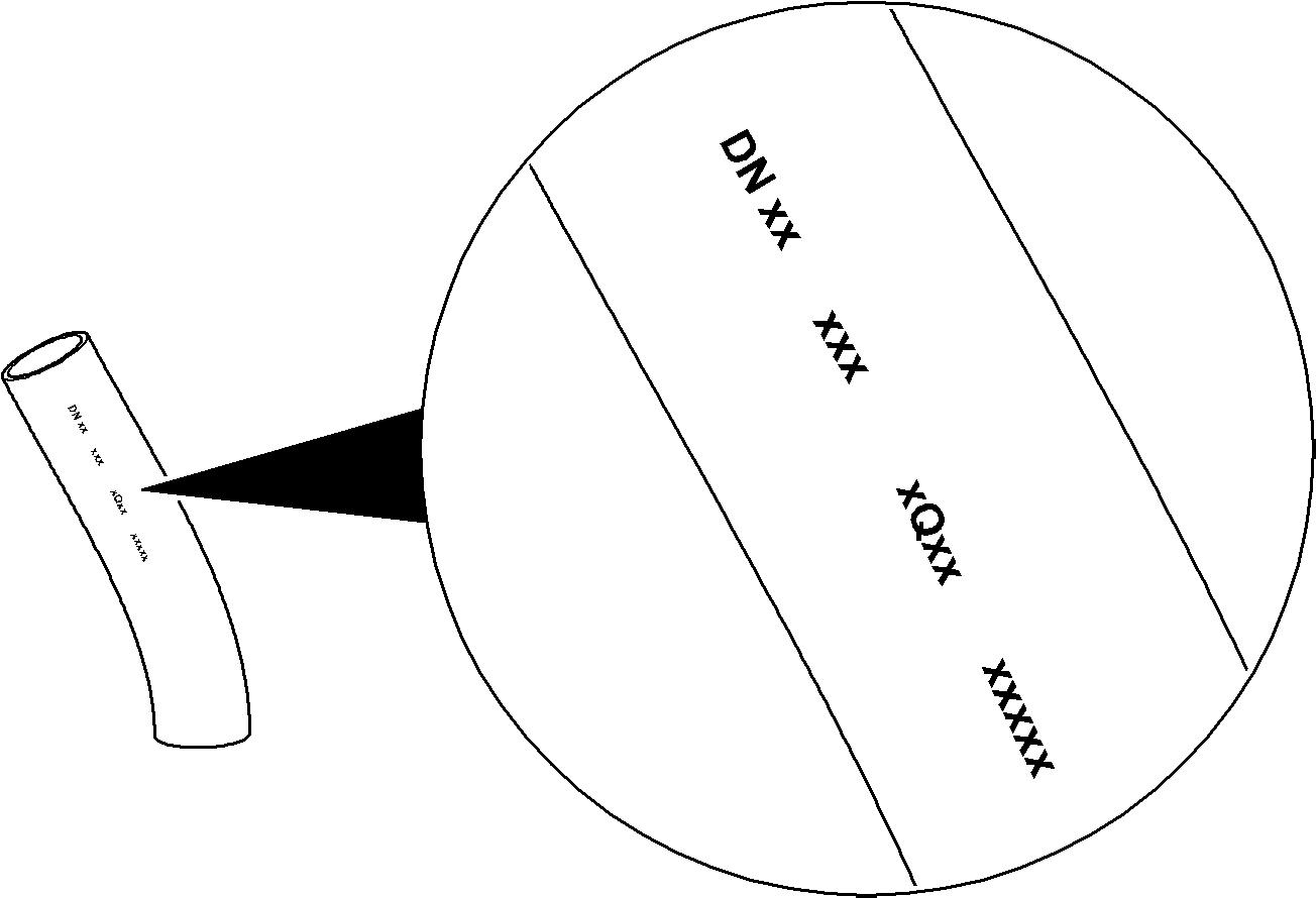
Hose marking
The hose is marked on the rubber cover with: se (i.e. 2Q13 = second quarter of 2013)
Hose assembly marking
The hose assembly is marked on the fittings with:
Visual check of the hydraulic hoses
Normal conditions of use
Danger!
Itisnecessarytoreplacethehydraulichosesatspecifiedintervalstomaintaintheir maximum operating performance and to reduce the risk of personal injury and/or machine damage.
Obey the replacement intervals given below.
Natural ageing
Hydraulic hoses and hose assemblies undergo a process of natural ageing. Thus, their service life has a limit: stobeytherequirementsgiveninthesection "Replacement of the hydraulic hoses" of this manual.
When you check a hose assembly or you install a new one, refer to the date of assembly marked on the hose assembly fittings.
Operating stress
Thehydraulichosesmustalsoberegularlyreplacedbecauseoftheoperatingstress. Forthereplacementintervalsgiveninworkinghoursofthehydraulichoses,refer to the section "Control and maintenance chart" of this manual.
Mounting instructions
Refer to the Operating Manual.
6.1.3Components functions
This section gives the function of the different main components of a hydraulic hose assembly.
Insiderubber tube
The inside rubber tube keeps the conveyed fluid in the hose. It is resistant against thefluidandthetemperatureofthefluid.Internaldamagestothistubecanbecaused by contamination of the hydraulic circuit.
The inside rubber seals the hose but it has no pressure stability.
Reinforcement layer
Thereinforcementlayer,madeupofsomesteellayerswithrubberinbetween,holds the internal pressure.
The reinforcement layer is theonly componentof the hose whichgives thehose the pressure stability. The hose has a minimum burst pressure (static) and a maximum operating pressure (dynamic). The maximum operating pressure is usually at least four times lower than the minimum burst pressure because dynamic pressures fatigue the reinforcement layer more quickly than static pressures.
The value of the burst pressure and the operating pressure will be lower if the reinforcement layer has one of the damages that follow:
The inside rubber can also be damaged if the reinforcement layer moves.
Rubber cover
The rubber cover protects the reinforcement layer from the ambient conditions (UV, ozone, different liquids) and from mechanical effects (scrubbing, corrosion).
Anyrub,cutorribintherubbercovermeansthattheprotectionisnolongersatisfactory and the reinforcement layer is subject to a potential destruction.
Nipple
Thenippleisnecessaryto connecta hydraulichoseto anothercomponent. Thenipple is resistant to all the mechanical forces and bending stress caused by the pressurepulsationsinthehose.Thus,itisimportanttohaveagoodcontactbetweenthe nipple and the hose.
Cracks on the nipple cause its fast failure.
Crimp fitting
To make sure that the assembly is correctly sealed, the crimp fitting presses the inside rubber tube onto the nipple. In addition, if the hose has a wire trap area, the crimp fitting clamps the reinforcement layer in between the nipple and the crimp fitting.
Ifthe hoseassemblystarts to leak at the end of the crimp fitting, the causes that follow are possible:
6.1.4Recommendations for hose assembly maintenance
Severity levels
Hose assembly damages can be divided into three severity levels: For each severity level, there are special actions to do at specific intervals.
Checks and recommendations
The sections that follow give: makeanestimateofthedamageseverity level
Visual check of the hydraulic hoses
Minordamage
If you find a minor damage:
Daily
Examine the hose assembly. Monitor if the deterioration increases. In case of rubbing, move the hose assembly to make sure there is no more contact.
Check all necessary conditions forthe possible replacement of the defective part(s)(e.g. part in stock, time of delivery).
Rubber cover is rubbed -Reinforcement layer is not corroded or not rubbed - No sign of oil
Rubber cover has a cut or a crack - Reinforcement layer is not corroded or not cut - No sign of oil
Hose is visually wet near the crimp fitting - Oil does not propagate There is a small surface of remaining oil which is visually wet but does not result in the formation of drop.
Dry dust collection which does not propagate
Immediately
Seriousdamage
If you find a serious damage:
Inform formally the responsible Maintenance Manager about the condition of the hose assembly.
Make sure that you have the correct replacement part in stock.
Examine the hose assembly. Monitor if the deterioration increases.
Daily
One of the next services, but not later than 250 hours
Ifthedeteriorationofthehoseassemblyincreasesinasmall numberofdays, refer to next section "Major damage" for the actions to do.
Replace the hose assembly.
Rubber cover has many cuts or cracks - Reinforcement layer is not corroded or not cut - No sign of oil
Rubber cover is rubbed - Reinforcement layer is uncovered but not corroded - No sign of oil
Hoses and fittings are visually wet - Oil propagates There is a surface of remaining oil which is visually wet and results in the formation of non-falling or falling drop.
Visual check of the hydraulic hoses
Majordamage
If you find a major damage:
Danger!
Inthiscase,thehoseassemblymustbereplacedimmediatelybecauseitcanburst at any time.
Obey all safety instructions given in the Operating Manual to avoid accidents and fires.
Stop the machine immediately (no exception).
Immediately
InformformallytheresponsibleMaintenanceManager,orhissuperior,thatthe machine is stopped and about the condition of the hose assembly.
Before restart the machine Replace the hose assembly.
Oil leakage
The frequency of the drops makes a measurable flow.
6.2Centralized lubrication system
1.MainScreensandControlButtons
Menu:UsedtoEnterintoMenuListandreturntoPreviousMenu.
Up:UsedtomoveupcursorintheMenuListsandtoincreaseaValue.
Down:UsedtomovedowncursorintheMenuListsandtodecreaseaValue.
Themainmenuisaccessedthroughthe"Menu"button;allthemenusaredisplayedontherightdisplay.
InagivenMenulist,youcanpressthe"Up"and"Down"buttonstoscrollthroughmenus.Pressingthe buttonwillthenscrollthroughmenusfromtopofscreentothelastmenuonscreen;butifthe buttonis pressed,selectionwillscrollfromtoptobottomofmenuslist.
Theactivelineis"inversevideo"(whitetext,blackhighlighted),usethe"Menu"keytogetinsidetheselected submenu.
Thelastlineofamenulistisalwaysdefinedas"Back",itisusedtomovetothepreviousmenubypressingthe "Menu"buttonwhenhighlighted.
WithinagivenMenuwherethevaluecanbechanged,thechangecanbemadebyusingthe"Up"buttonto increasethevalueandusingthe"Down"buttontodecreasethevalue.Changesareimmediatelyregisteredin controller.Pressingthe"Menu"buttonreturnsyoutothepreviousmenu.
StartCycle
Thethreekeys"StartCyclePX"canbeusedtostartanewlubricationcycleatthecorrespondingpump.Pushing thisbuttonsactslikesimulatinganEnablingsignalcomingtothegreasingcontroller, foreachpump independently.ThechosenpumpwillstartifthePilotpressureissufficient.
IfpumpPXisinsafetymode,athreesecondsactivationofthebutton makesthepumpPXreturnto thenormalmode.
Description of the software menus
2.StartScreens
LeftStartScreen: Grease Controller Startin g
RightStartScreen:
3.MainScreens
LeftMainScreen:
P1OFF
123bar 4 5 6 sec
P2ONSafet y bar0sec
P3ON 1 p ulse200sec
RightMainScreen:
LevelP1100%
P395%
PilotP 4 2bar
B150 12 p ulse
B150 21 p ulse
P2Safet y serv
4. ArchitectureofMenus


5. Menu
Infos y stem
Activeerrors
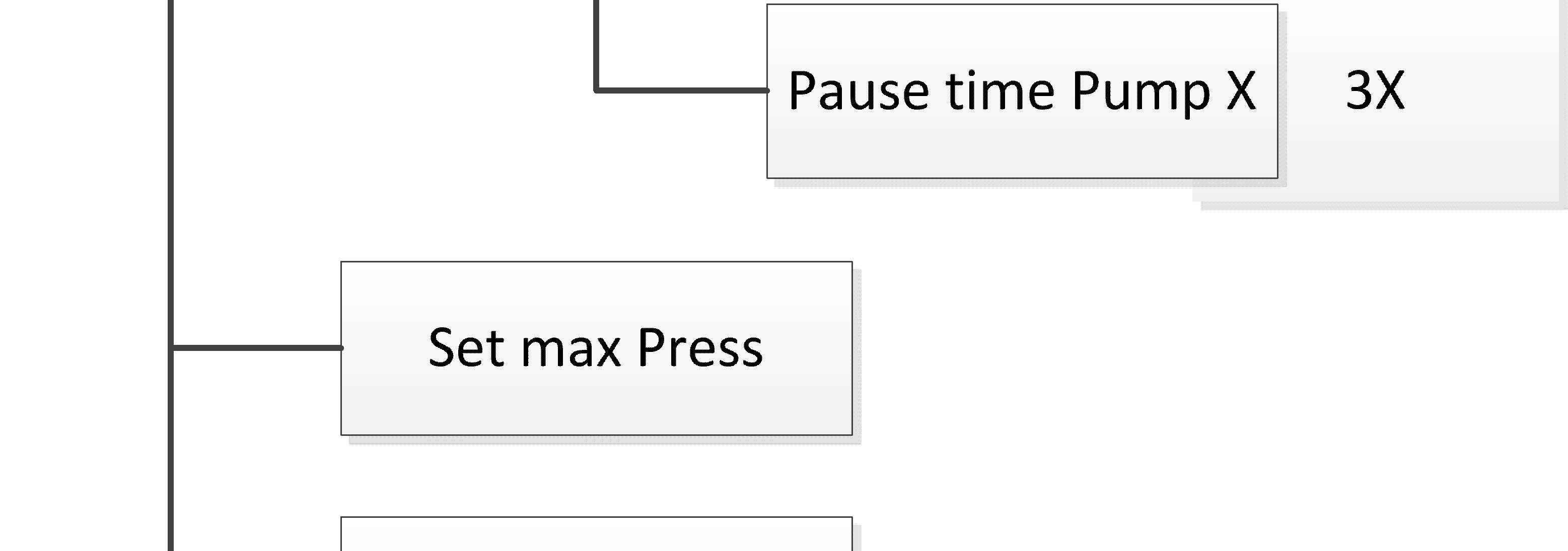
SetPausetime
Setmax p ress
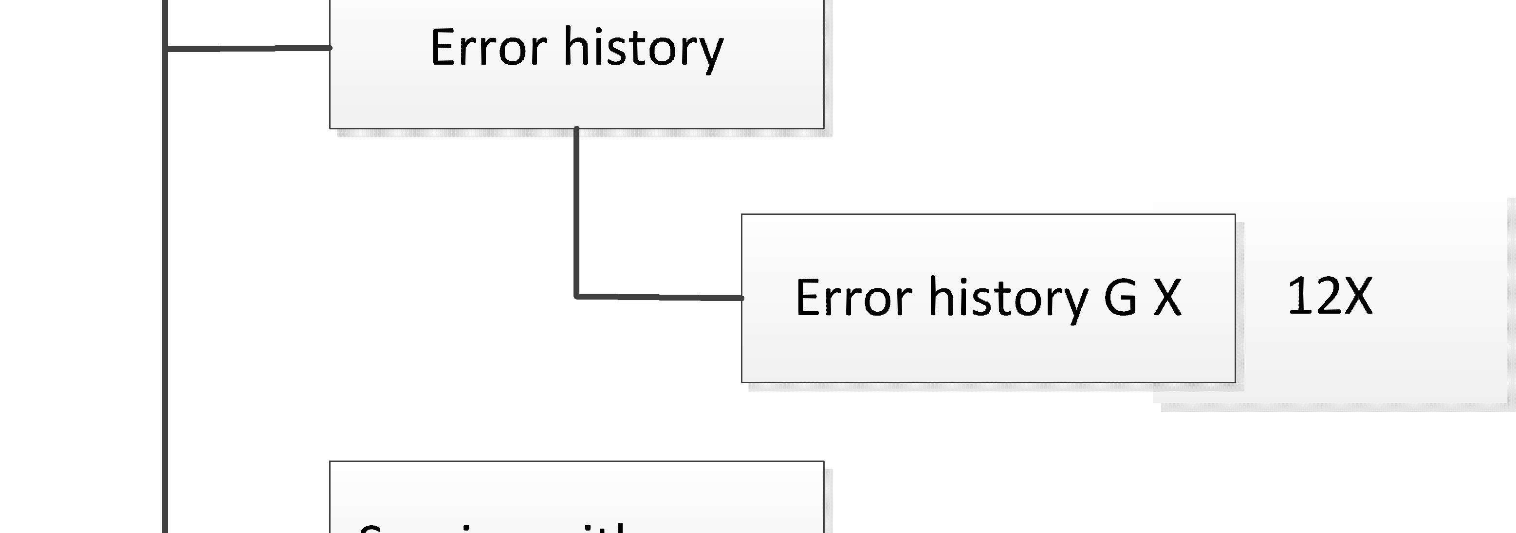
Errorhistor y
Psafet y serv
SetPausetime
Setmax p ress
Errorhistor y
Psafet y serv
Check Back
Check:
UponenteringtheCheckmenu,thestatusesoftheanaloguesensorsareshown.
B 6 9OK
B71OK
B1 8 4 OK
B5 0 1OK
B5 0 2E R R
TorepresentSensorvaluesinmA,pressandholdboth"Up"and"Down"arrowbuttonsformorethanthree seconds.Thiswillonlyapplywhenaserviceorinspectordongleisplugged.
B6912mAB713 4mA
B18 4 1
6mAB5112mA
B5 0 _121mA A
B5 0 _219m
B15 0 19mA
B15 0 29mA
6.Appendix
ErrorList:
Operating Manual
Centralized Lubrication Systems
R9250
Productidentification
Manufacturer: SKF Lubrication SystemsGermany GmbH
Type: R9250, R9250E
Type no.: R9250: 437 and 1357, R9250E:1129
Address
Heinrich-Hertz-Str. 2-8
69190 Walldorf - Germany
1 Guidelines
As you read theseinstructions, you will notice a number of depictions and symbols which are to facilitate the navigation and understandingof these instructions.
For reasons of better legibility, in these instructions we mainly use the male form for general references.Of course, the femaleformis alsoalways intended.
Please read these instructions thoroughly and heed the warning and safety notes. Please observethewarning and safety notesand exerciseparticular caution in these cases.
Informalso other usersaccordingly.
Text representations
Bold print
Meaning
Highlighting ofparticularly important words or passages
List 1 Marks lists o List 2 Marks lists
(parenthesis)
Instructions
Itemnumbers
Instructions to personnel. These always appear in chronological order.
Explanation of symbols and signs
Activities which generate actual hazards (to life and limb or possible damage to the material) aremarked by warnings. Definitely observe the instructions given in the warnings. Youwillfindthesesymbols,whichwarnofspecificdangerstopersons,materialassets,orthe environment, next to all safetyinstructions intheseoperating instructions.
Please read these instructions thoroughly and heed the warning and safety notes. Please observethewarning and safety notesand exerciseparticular caution in these cases.
Informalso other usersaccordingly.
Thefollowing warningsare possible.
Symbol Meaning
Generalwarning
Activities which generateactual hazards (to life and limb or possible damage to thematerial)
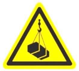
Warning of suspended load

Risk ofexplosion
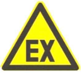
Carry out work on electricalparts only ifthe atmosphereis not potentially explosive. Workhas to be carried out by aspecialistfor maintenanceand repairs inpotentially explosive atmospheres.
Electrical component hazard, electrical shock hazard
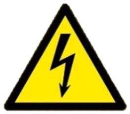
Make sure to disconnect the system or component from the power supply before carrying out works on electrical parts.
Do not use steam jet or high pressure cleaners for cleaning. Otherwise electrical components may be damaged. Do not touch cables or electrical components with wet or damphands.
Cleaning work on energized components may be carried out by electrical specialists only.
Risk offire
Risk of fireand explosion when using inflammablecleaning agents.

Health hazard
Hazarddue to spouting lubricant / pressureinjection due to a leakage (defectivefitting, too high systempressure orother damages).
Crushing hazard
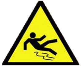
Slipping hazard
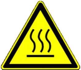
Hot surfaces
Symbol Meaning
Disposal
Environmentally sound disposal and recycling
Disposal
Environmentally sound disposal of waste electricaland electronic equipment
Illustrations
The illustrations used refer to a specific product. In the case of other products or product versions they may have a schematic character only. The basic function, however, does not change.
Abbreviations
The followingabbreviations may beused within these instructions:. max. maximum min. minimum min minutes s seconds etc. and so on poss. possibly e.g. for example ml millilitre ccm cubic cm mm millimetre
°C degrees Celsius
°F degrees Fahrenheit
K Kelvin inch inch etc. et cetera kg kilogram l litre mbar millibar no. Number
Nm Newtonmeter incl. including i.e. this means rh relativehumidity approx.approximately
Ø diameter
® registered trademark
© Copyright
TM Trademark
% per cent dB (A) sound pressure level
> greater than < less than ± plus minus
SW width across flats
ESD Electrostatic Discharge
N/A not applicable
Manufacturer and Service addresses
Manufacturer
SKF Lubrication Systems Germany
GmbH
Heinrich-Hertz-Str. 2-8
DE - 69190 Walldorf
Customer Service
SKF Lubrication Systems Germany GmbH
Heinrich Hertz Straße 2-8
DE - 69183 Walldorf
+49 (0)6227-330
SKF Lubrication Systems Germany GmbH
2. Industriestraße 4
DE - 68766 Hockenheim
+49 (0)620527101
SKF Lubrication Systems Germany GmbH
Motzener Straße 35-37
DE - 12277 Berlin
+49 (0)30-720020
Warranty
Theinstallationinstructionsdonotcontainanyinformationonthewarranty.Thiscanbefound in our general terms and conditions.
Copyright
© Copyright SKF Lubrication Systems Germany GmbH. These installation instructions are copyright-protected. All rights reserved.
The integration of the content into the manufacturer's installation instructions of the machine, into which the pump shall be integrated, is expressly allowed.
Thisalsoincludesthecreationoftrainingmaterial for internal,non-commercial purposes.Any other use without the written consent of the copyright holder - of whatever kind - is prohibited and is regarded as aviolation of copyright.
2 Safetyinformation
Safety information is to be read and observed by any persons entrusted with works on the centralized lubrication system or by those persons who supervise or instruct the beforementioned group of persons.
It is prohibited to commission or operate the machine, the centralized lubrication system or single components prior to reading the installation instructions. The installation instructions must be keptat an accessible location for further use.
Disclaimer
Observation of these installation instructions is the prerequisite for safe operation and the achievement of productcharacteristics and performance levels.
The manufacturer shallnot be held responsible for damages causedby: o nonappropriateuse,faultyassembly,operation,setting,maintenance,repairoraccidents o improper or late response tomalfunctions o unauthorized modifications of the product o intent or negligence o Use of non-original SKF spareparts.
Liability for loss or damage resulting from the use of our products is limited to the maximum purchase price. Liability for consequential damages ofwhateverkind is excluded.
Emergency stopping of the centralized lubrication system
Incase of anemergencystop thecentralized lubrication systemby: switching off the machine, system or vehicle, into which the SKF centralized lubrication system or its componentshavebeenintegrated. separating the supply of power, compressed airor hydraulic pressure (dependingon the system) to thecentralized lubrication system or the corresponding components. actuatingthe emergency-offswitch, if any, of the machine, system or vehicle.
Intended use
ATTENTION
Allproductsmay be used onlyfor theirintendedpurposeand inaccordancewith the instructions.
Intendeduseistheuseoftheproducts to lubricatebearings andfrictionpointswith lubricants within the physical limits that can be found in the relevant product documentation, e. g. operating instructions and product descriptions, e. g. technical drawings and catalogues.
Operation of the lubrication system or single components of it
Operation ispermitted only, if in compliance with:
Allinformation given inthese installation instructions or stated in the referenced documents.
All laws andregulationsto be complied with by the user.
Properly andappropriately conducted installationof the system.
Foreseeable misuse
Any other use and purpose of the centralized lubrication system or its components than the ones described before arestrictly prohibited.
Use isexpresslyforbidden:
in a potentially explosive atmosphere, unless the centralized lubrication system or its components are expressly suitable for itand have been approved accordingly.
in a working environment or condition that corresponds to the required protection types IP (International Protection) and Nema (National Electrical Manufacturers Association) only inparts or not at all.
to use the CLS to feed, forward, or store hazardous substances and mixtures in accordance with annex I part 2-5 of the CLP regulation (EC1272/2008).
Forthesupply,transport,stockpilingofgases,liquefiedgases,dissolvedgases,vapours, andfluidswhosevapourpressureexceedsnormalatmosphericpressure(1013 mbar)by more than 0.5 bar at the maximumadmissible operating temperature. to use the CLSto feed, forward, or store glycol- or polyglycol based oils and greases. to use inadmissible components or components expressly not suitable for the purpose.
Unauthorised activities
The following activities may be carried out by SKF manufacturer specialists or authorized persons only due to potential sources of faults that may not be visible for the user, or due to legal regulations:
Removal, replacement or changes to the centralized lubrication system or components integrated or connected to it.
Changes to the control printed circuit board or the power supply board exceeding the adjustment of lubrication and pause times or thereplacement in caseof defects.
Dismantling of individualcomponents of the centralized lubrication system. Changesto the power supply or to the admissibleinput voltage.
Changes to the admissible or specifically required operating pressure for the supplied centralized lubrication system.
Conversions or modifications
Unauthorizedconversionsormodificationsmayresultinunforeseeableimpactsonsafetyand functionality. Therefore, any unauthorized reconstructions or changes are expressly prohibited.
Inspections
Thefollowing inspections were carried out prior to delivery: Electrical inspections following EN 60204-1 (depending on the type of component supplied) Tests made in accordance with ATEX (depending on the type of component supplied)
Safety and functional tests (depending on the type of component supplied)
Warning labels on the centralized lubrication pump or system

Hand injurywarning
During operation of the centralized lubrication system,particularly of the pump, never remove the lid or the barrel andreach into the reservoiror the barrel. Risk of trapping or shearingoff hands and fingers!
Electric shock
Connection of 24 V DCcomponents mustbe provided by a safe galvanic isolation PELV (ProtectiveExtraLow Voltage) or SELV (Safety Extra LowVoltage) always.
Other applicable documents
Inaddition tothese installation instructions,the following documents mustbe observed by the respective target group:
Operational instructions andreleaseprovisions by theoperator.
Safety data sheet and operating instructions of thelubricant or material used. The operator must ensure adding them to these installation instructions.
Operating instructions and technical descriptions of the components used inthe centralized lubrication system.
Operating instructions and technicaldescriptions of purchased parts.
Where appropriate:
Projectplanning documents.
Other relevant documents for the integration of thecentralized lubrication systeminto the superiormachine or system.
The owner must supplement these documents by the respective valid national or regional regulations laiddown by the country inwhich the centralized lubricationsystemis to beused. Ifthecentralized lubrication systemissoldortransferred, anyassociateddocumentsmustbe passed on to the subsequent operator as well.
Sources of hazard
The centralized lubrication system and the components used have been designed, built and tested usingstate-of-the-art technology.
Depending on their version and necessity, they will have left our company only after having passedstringentsafetyandreliabilitytests.Likeforallcomplexmachines,alsoforthissystem there may stillbe involved potential sources of hazard.
Moving or rotating parts
Drive
Tooth wheels
Stirringpaddle
Shovelfoot
Piston Guides
Articulations etc.
Energies
Electricity
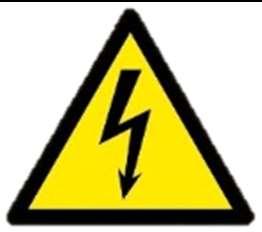
Temperature(hot orcoldsurfaces)
Position energy (raisedcomponents)
Parts subject topressure(operatingpressure, oilpressure, greasepressure, airpressure, etc.)
Bursting reservoir if filled by ahigh-performancepump
Parts subjectto spring tension
Lubricants
Greases
Oils
Transportlifecycle
Residual risks Remedy
Tilting or fallingof parts during transport, e.g. overinclines.
Secure parts against tilting or falling during transport (e.g. using tapes, belts, ropes,etc.).
Dropping of lifted parts or tools. No people may remain under suspended loads. Keep unauthorized persons away. Secure suspended loads using suitable hoisting equipment (e.g. tapes, belts, ropes, etc.).
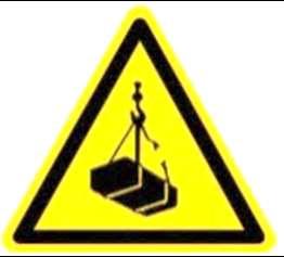
Existing residual risks
Installation lifecycle
Residual risks Remedy
People slipping due to floor contamination with spilled or leaked lubricant
Take care when filling. Bind and remove leaked or spilled lubricant immediatelywith a suitable agent.
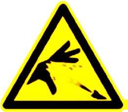


Follow the operational instructions for handling lubricants and contaminated parts.
Installation lifecycle
Residual risks
Deviating installation position.
- Foreign objects falling into the motor air intake or into other components.
- Borehole for drainage of condensation water is no longeratthelowestpointof the motor.
Tearing or damaging of lines when installed on moving machineparts(e.g.pivotarm).
Tearing or damaging of lines due to installation on chafing points or installation with too littlebending radius
Falling of parts dueto insufficient fixingto the machine.
Remedy
Installation of a suitable protective roof over the air intake.
Deviating installation position only, if the formation of condensation water has been completed. Remove condensation with suitable suction device.
If possible, do not mount onto movable parts. Should thisnot bepossible,use flexiblehoselinesofsufficient length.
Use protective pipes or spring coils.
Fix parts only to machine parts with sufficient load capacity. Observethe weight and the stated tightening torques.
If no tightening torques are stated, the tightening torques are to be applied to the screw size for 8.8 screws.
Literature, see screw manufacturer. Electric shock through reduced insulation resistance. Check the formation of condensation water inthe motor regularly.
If applicable, drain off condensationwater at the drain plug. Check the insulation resistanceregularly. Electric shock when connecting thepump. Prior to connection of electrical components (pump, switchcabinet,valves, etc.) de-energizeallaffected electrical components. If necessary, please observe discharge times.The electrical connection may be carried out by commissioned andqualified electricians only and inaccordancewith the connection diagram.
Lifecycle - commissioning
Residual risks
Electricalshock dueto defective connection cable
Remedy
Beforeinstallation andstart-up check allcables with regardto possibledamages.
Incase of damage, properly replace affectedcable. Immediately switch off the centralized lubrication system.
Lifecycle - commissioning
Residual risks
Lubricant spraying out due to incorrect screwconnectionof components or lines.
Remedy
Tighten allparts with appropriate tightening torques. Use suitable hydraulic screwconnections and lines for the stated pressures.
Check these prior to commissioningfor correct connection and damage.
Contactwith corrosive or toxic substances that maybe set free by a defective battery.
Wear protective clothes.
Ensuresufficient ventilation. Storage and disposalof defective batteries in accordancewith the corresponding safety data sheets for lithium.
People slipping due to floor contamination with spilled or leaked lubricant.
Take care when filling. Bind and remove leaked or spilled lubricant immediately with a suitableagent.
Observe the legal or company regulations on dealing with oils and greases and contaminatedparts.
Falling of parts dueto insufficient fixingto the machine.
Fix parts only to machine parts with sufficient load capacity. Observethe weight and the stated tightening torques.
If no tightening torques are stated, the tightening torques are to be applied to the screw size for 8.8 screws.
Literature, see screw manufacturer.
Bursting reservoir if filled by a high-performancepump
Monitor the filling procedure and stop it when reaching the maxmarking ofthe reservoir
Contact withstirring paddleor shovel foot during "test operation" without lubricant reservoiror barrel
Tearing or damaging of lines when installed on moving machineparts(e.g.pivotarm).
Alwaysoperatepumpwith lubricantreservoiror barrel. Do not reach into the stirring paddle, the drive or the supply piston.
If possible, do notmount on moveable parts.
Should this not be possible, use flexible hose lines of sufficient lengths.
Lifecycle - operation, maintenance, repair Residual risks Remedy
Contact to the shovel foot during change of barrel of a pneumatic, hydraulic or electric barrel pump.
Contactwith the stirring paddlewhen filling a reservoir pumpfrom thetop during pumpoperation.
Change barrel only with the centralized lubrication system and pumpbeing de-pressurized.
Switch off the pump before changing the barrel and relieveexisting system pressure.
Fill preferablyvia the filling connection.
Filling fromthe top or changing ofbarrel in case of barrel pumps onlywhile thepumpis idle.
When filling, donot reach into the reservoir.
Electricalshock dueto defective connection cable
People slipping due to floor contamination with spilledor leaked lubricant
Switch off the centralized lubrication system and check connection cablefor damage.
Exercisecaution when connecting the system. Promptlyapply suitablebinding agents to remove the leaked orspilled lubricant.
Follow the operational instructions for handling lubricants and contaminated parts.
Tearing or damaging of lines
Switch of the centralized lubrication system, check the routing of the hose lines and optimize or replace defective hoseor line, if necessary.
Should this not be possible, use flexible hose lines of sufficient lengths.
Faultlifecycle
Too strong heating up of the motor or other electrical components.
Too strong heatingup of hydraulicallydriven components
Strong coolingdown and formation of ice onsound absorber and air leakage on pneumatically driven pumps or other components
Inadmissible lubricant leakage oncomponentsor lubricantlinesof the centralized lubrication system
Switch off the pump and system. Let parts cool down, eliminate cause. Replacedefective motoror other defective components.
Switch ofthe system or the affected component.
Ensureproperfunctioning ofthe oil cooler.
Check the compressor and the drier ofthe compressedairsupply. Reduce the operating speed of theaffectedpump.
Shortly switch off thesystem or heat it, if necessary.
Switch off the centralized lubrication system and determine cause. Replacedefective lines or components.
Faultlifecycle
Lubricant spraying out due to incorrect screwconnectionof components or lines.
Tighten allparts with appropriate tightening torques. Use suitable hydraulic screwconnections and lines for the stated pressures.
Check these prior to commissioningfor correct connection and damage.
Disposal lifecycle
Contamination ofthe environment withlubricant and wetted parts
People slipping due to floor contamination with spilledor leaked lubricant.
Dispose of theparts following the valid legal and company regulations.
Exercise caution when disconnecting the lines. Promptlyapply suitablebinding agents to remove the leaked orspilled lubricant.
Follow the operational instructions for handling lubricants and contaminated parts.
Contamination ofthe environment due to used batteries on control printed circuit boards
Dispose ofusedbatteries followingthe valid legal and company regulations.
Until disposal, store used battery, e.g.in a closed polyethylene bag , in order to avoidany damages.
Persons authorized to operate the pump
Only qualified technical personnel may install, operate, maintain, and repair the products described in this document. The core principles of these country-specific qualification requirements for technical personnel cannot be below those of the two standards mentioned above.
Operator
A person whois qualified bytraining and experienceto carry out the functions and activities related to normal operation.
This includes avoiding possiblehazards that may arise during pumpoperation.
Specialist for maintenance and repairs
Qualifiedtechnicalpersonnelarepersonswhohavebeentrained,assigned,andinstructedby the operatorof the final product. Such persons are familiar with the relevant standards, rules, accident prevention regulations, and assembly conditions as a result of their training, experience, and instruction.
They are qualifiedto carry out therequired activities and indoingso recognize and avoid any potential hazards.
Specialist in electrics
The definition of qualified personnel and the prohibition against employing non-qualified personnel are laid down in DIN VDE 0105 and IEC 364. Relevantcountry specificdefinitionsof qualifiedtechnicalpersonnelapplyforcountriesoutsidethescopeofDINVDE0105orIEC364.
Protection of special groups of persons
The respective legal employment restrictions do apply.
3 Safetyrecommendationstobecompliedwith
General behaviour when handling the system
The centralized lubrication system,pumpor single components may be used only in awareness ofthe potential dangers, in proper technical condition, and according tothe information inthese installationinstructions.
Familiarize yourself with the functionsand operation of the product. The specified assemblyand operating steps and theirsequences must be observed.
Any unclear pointsregarding proper condition or correctassembly/ operation must be clarified. Operation is prohibited untilissues have beenclarified.
Keep unauthorized personsaway from the centralizedlubrication system.
Precautionary operational measures and instructions for the respective work must be observed.
Responsibilities for different activitiesmust be clearly defined and observed. Uncertainty seriously endangerssafety.
Safety-related protective and emergency devices must not be removed, modified or affected otherwiseintheirfunction and areto be checked at regular intervals for completeness and function.
Remedy occurring faults inthe frameof responsibilities. Immediately inform your superior inthecase offaults beyond your competence.
Do not reachinto thesystem during operation.
Wear personal protectiveequipment always.
When handling lubricants observethe relevant safety data sheets and operating instructions bythe lubricant manufacturer or supplier.
Never use parts of the centralized lubrication system or of the machineas standingor climbing aids.
Explosion protection
Always behaveso that fireand explosion hazards are avoided.
A writtenwork approvalfromthe operator is required prior to working inpotentially explosive areas.
There must be no indications that parts of the explosion protection aremissing or are not working. Should such indications become apparent, switch off the machineand informa superior without delay. Keepunauthorized personsaway.
Measures forexplosion protection must never be deactivated, modifiedor bypassed.
It is forbidden to bring inignition sources such as sparks, open flames and hot surfaces in potentially explosive areas.
Check the machine at regular intervalsfor damage whichmay represent an ignition risk.
The ignition temperatureof the lubricant must lie at least50 K over the maximum admissiblesurface temperature of the components.
Only use tools andclothing which are permitted for usein potentially explosive areas (ESD).
Transport, installation, repairs and work on electrical components may only be carried out, if it has been ensured that the atmosphere is not potentially explosive.
Repairs or modifications to machines which are protected against explosions may be carried out onlyby themanufacturer or by a workshop recognized by a named institution and confirmed in writing.
If thework is not carriedout by themanufacturer,the repairs must be approved by a namedexpertand confirmed inwriting. The repairs are to bemarked by a repair sign on the machine, stating the following: o Date o Executing company o Type of repair o If applicable, expert'scode
Transport damages can result in the loss of the explosion protection. If transport damages canbe seen,do not assemblethe machine or put it into operation
All parts of the earthingconcept mustbe correctly availableand connected with the superordinate machine.
If transport lugsare dismantled after set-up, the threaded bores mustbe permanently sealed in accordancewith the protectionclass. Handle the materials so that no sparksare generatedby tilting,falling,sliding, rubbing, impacting,etc. If needed, cover materials with suitable means.
Never disconnect plug-in connections when energized. Secureplug-in connections against inadvertent manualdisconnection with the safetyclips included inthedelivery.
The operator must check critically whether operationwithout a low-level signalmight lead toa new risk potential(e.g. throughheat-up of bearing points on themachine in the area of ignition temperature, poor lubrication or bearing damage). If this cannot be ascertained,provide a low-level signal or suitableorganisational measures for monitoring of thebearing point temperature.
Avoiddust accumulation and removedust immediately. Dust accumulations havea thermally insulating effectand, ifwhirled up, generatethe formationof a potentially explosiveatmosphere.
The pumpshould be integratedinto the operator's lightningprotection concept.
All parts are to bechecked regularly for corrosion. Replace the affected parts.
Terminalboxesmust befirmly closedand the cablebreakthroughs correctly sealed.
Additional electrical monitoring devices must be firmly connected and correctly adjusted.
Protect the motor with a motor circuit breaker against inadmissible heating up. When reachingtheirnominallife,themotorbearingshavetobereplacedorinspectedtoensure their suitability for further utilisation.
Transport / installation / maintenance / repairs / servicing
All relevant persons (e.g., operating personnel, supervisors) must be informed of the respective activity prior to starting any work. Observe the precautionary operational measures and work instructions.
If protective and safety equipment has to be dismantled, it must be reassembled immediatelyafter finishingthe work,and then checked for correct function.
Ensurethroughsuitablemeasuresthatmovableordetachedpartsareimmobilizedduring the work and that no limbscan be caught in betweenby inadvertentmovements. Carry out transportusingonly suitablehoisting equipment.
If transported separately(e. g. repair)lift themotor bymeans of the transportlugs or eye bolts. Ensure that transport lugs or eye bolts are firmly seated. Do not carry any further load onthe transportlugsor eyebolts. Do not transport motors on the fancover.
Assemblethepumpsandothercomponentsonlyoutsideoftheoperatingrangeofmoving parts,at an adequatedistancefrom sources of heat or cold.
Dry wet, slipperysurfaces.
Cover hot or coldsurfaces accordingly.
Prior to performing work, de-energize and depressurize the pump and secure it against unauthorized switch-on. Work on electrical components must be carried out by electrical specialists only. Observe anywaiting periods for discharging, if necessary.
Carry out electrical connections only according to the information in the valid wiring diagram and takinginto account the relevant regulations, thelocal connection conditions andlegalprescriptions(e.g.DIN,VDE).Electricalconnectionsmustbedoneinsuchway that no forces are transferred to the product (tension-free connection).
Do not touchcables or electrical componentswith wet or damphands.
Maintenance and repair work can be subject to restrictions at low or high temperatures (e.g. changedflowpropertiesof the lubricant). Therefore, wherepossible, trytocarryout maintenanceand repairworkat room temperature.
Carry out all works on electrical components using adequate, voltage insulated and technically proper tools only.
Fuses must never be bridged but have to be replaced by the same type of fuse always. Determine the causeof thefailure of the fuse.
Ensurecorrect earthingof the electrical system.
Undertake drilling at non-critical, non-load bearing parts only.Use any available boreholes. Donot damagelines and cables when drilling. It is essentialto observe the machine manufacturer's installation instructions and to consult themachine designer in case of doubts.
Observe possibleabrasion points. Protect the parts accordingly.
Other units of themachine or vehicle must not be damaged or impaired in their function by the installation of the centralized lubrication system.
All components used must be designedfor: o maximumoperating pressure o lubricant to be supplied o maximum/ minimumtemperature o corresponding supply voltage availableon site o operating and ambient conditions at the locationof use o requiredlubricant volume
Parts of the centralized lubrication system must never be subjected to torsion, shearing or bending.
Check all parts prior to use for contamination and clean, if necessary. Lubricant lines shouldbeprimedwithlubricantpriortoinstallation.Thismakesthesubsequentventilation and commissioning of the system easier.
Observe the specified tightening torques. When tightening, use a calibrated torque wrench.
When working with heavy parts usesuitableliftingtools. Ifneed be,consultthe responsiblesafety officer.
Avoidmixing up or wrongassembly ofdismantled parts. Mark these parts accordingly.
Laying of the lubrication lines
Whenlayingthelubricationlines,observethefollowinginformationinordertowarranttroublefree function of the entire centralized lubrication system.
Caution
Environmentalpollution

Lubrication lines must be absolutely leakproof. Lubricants maypollute ground andwaters.Lubricantshavetobehandledanddisposedofproperly.Observeall applicableprescriptionsandlawsregardingdisposaloflubricantsaswellasthe relevantsafetydatasheets.
Slippinghazard
Centralizedlubricationsystemsmustbeabsolutelyleakproof.Leakinglubricant ishazardousduetotheriskofslippingandinjury.Duringassembly,operation, maintenanceandrepairofcentralizedlubricationsystemswatchoutforleaking lubricant.Leaksmustbesealedimmediately.
Dimensionthelubricationlineaccordingtothemaximumpressureandtheoutputvolume of thepumpunit used.
Starting from the pump unit the main lubrication line should be laid preferably rising with a possibility to vent it at the highestpoint of thelubricationline system.
Mount the lubricant metering devices at the end of the main lubrication line in such way that the outlets of the lubricant metering devices show upwards. If lubricant metering deviceshavetobemountedbelowthemainlubricationline,thenthisshouldnotbedone at theend of the main lubrication line.
Thetubelines,hoses,shut-offandwayvalves, fittings,etc.haveto be laidoutaccording to the maximum operating pressure of the pump unit, the admissible temperatures and the lubricants to be supplied. Furthermore, the lubrication line system must be protected against inadmissibly high pressure.
Before the assembly thoroughly clean all components of the lubrication line system like tube lines, hoses, shut-off and way valves, fittings, etc. In the lubrication line system no seals should protrude towards the inside, as the lubricant flow could be impeded and contaminations could enterthe lubricationline system.
Lubrication lines shall generally be laid in such way that there can never be created air pocketsatanypoint.Avoidchangingthecrosssectionsofthelubricationlinefromsmaller tolarger crosssectionsin thelubricant flowdirection.Designcrosssectiontransitionsas smooth as possible.
The lubricant flow in the lubrication lines should not be impeded by the installation of sharpelbows, anglevalvesandcheck valves. Provide unavoidablechangesof the cross sections in the lubrication lines with as smooth transitions as possible. Avoid sudden changes of direction, if possible.
Initial commissioning / daily start-up
Ensurethat:
The machine manufacturer's instructionsregarding the lubricants tobe used are observed.
Allsafety devices arecompletely availableand functional. All connections are correctly connected. Allparts arecorrectly installed.
All warning labels on thecentralized lubrication systemarecompletely available, highly visibleand undamaged.
Illegible or missing warning labels areto be replaced without delay.
The system pressurespecifiedfor proper operation is adheredto and neither exceeding nor falling belowspecification.
Cleaning
Risk of fire and explosion when using inflammablecleaning agents. Only use nonflammablecleaningagents suitablefor the purpose.
Do not use any aggressive cleaningagents.
Donotusesteamjetorhighpressurecleaners.Otherwiseelectricalcomponentsmaybe damaged. Observe the protection classes, e.g. IP (International Protection) and NEMA (National Electrical Manufacturers Association), required for proper operation.
Cleaning work on energizedcomponents may be carried out by electrical specialists only.
Do not touchcables or electrical componentswithwet or damphands. Mark damp areas accordingly.
4 Operatorobligations
Determination of hazards
The operator must determine all hazards resulting from the integration of the pumpinto the superordinate machine and the hazards at the location ofoperation of the machine, and carry out the measures necessary to ensure safety and health protection.
Provision of necessaryinformation
The operatormust make the installationinstructions required for the respectiveactivity accessible to allpeoplecommissionedwithoperation,maintenance and repairs.
Hemustensurethat these people have read and understood the necessaryinstallation instructions.
The sameappliesfor allrelevant safetydata sheets,company instructions, accident prevention regulations, instructions fromsuppliers of purchaseparts and utilities. Depending onthe business organization, the relevant installationinstructions may have to be made accessible to other people and departments.
Inspection for correct use
The operatormust check atregular intervalsthrough suitable measures that thecentralized lubrication system is being used according toits intended purpose,that no conversions or manipulations have been made to the centralizedlubrication systemor to singlecomponents and that all parts arefully functional.
Briefing of external technicians
Prior to commencing theactivities, external technicians must be informed by the operator of the company safety provisions,the applicable accident preventionregulations to be maintained, and the functionsof the centralized lubricationsystem and protective devices.
Provision of personal protective equipment
The operatormust provide suitable personal protective equipment for the respective location of operation andthe purpose of operation.
Training courses
Inorder to provide a maximum of safetyand economic viability, SKF carries out detailed producttraining courses. It is recommendedthat the trainingcoursesare attended. Please contact SKF Customer Service for information.
Inspection of the delivery / returns
The delivery must be inspectedfor completeness based on the delivery papers.Transport damages mustbe reportedto the forwarder immediately.Keep the packaging material until any discrepancies are resolved.
Returns
Clean all parts and pack them properly, i.e. following the regulations of the recipient country, before returning them.Mark returns on the packaging as follows;
Donot burden / this side up!
Protect against moisture!
Handle with care! Fragile, do not throw!
Disposal
At the end of their service life, the centralized lubrication system and its components must be dismantled and disposed of according to the respective valid provisions in an environmentally friendly manner. It is forbidden to use parts of a centralizedlubricationsystemthatistobedisposed ofortoassemblethesepartstobuildanewsystem.
In case of a final shutdown follow the applicable rules and regulations on the disposal of contaminatedpartsormeansofoperation.TheproductcanalsobereturnedtoSKFforproper disposal, in which case the customer is responsible for reimbursing the costs incurred. The parts arerecyclable.

Caution
Lubricants may pollute ground and waters. Lubricants have to be handled and disposed of properly.
Observe the instructions by the machinemanufacturer regarding the lubricants to be used.
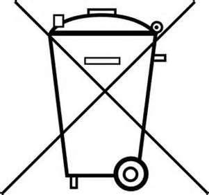
5 Lubricant
For lubricant information, refer to chapter 5.3 “Lubricants and operating fluids” ofthe Liebherr Operating Manual
Filling of the reservoir
Warning
Riskof hand injuries caused bythe stirring paddle or shovel foot
Fill lubricant via the lid only when pumpis idle. Never reach into the reservoir or grease barrel while the pump is running.
Observe extremecleanlinesswhen topping up the grease reservoirs. Contaminated lubricant causes malfunctions and premature wear of the greasepump and other componentsof the system. Clean surroundings beforeexchanging or topping up Switch off centralized lubrication system
Filling ofthe container through service-plate
Remove dust protective cap at the filling coupling and the dust protective cap at the filling nipple
Couplethe filling hose for P1 resp. P2 and switchon the filling pump
When the reservoir is full,the sensor transmits an electric signalto the controlunit. Visual control is possible by using the dipstick
When the filling pump is switched off Disconnect the filling couplingand reinstall the dustprotective caps
Inadvertent filling with incorrect lubricant
Should incorrect lubricant have been filled, pleaseproceedas follows: Switch off the pump orcentralized lubrication systemand secure itagainst being switched on.
Remove lubricant.
Clean the entirecentralized lubricationsystem (lubricant reservoir, pump housing, metering devices and line systems).
Fill inlubricantof correct specification. Switch thesystem or pumpon. Vent lubrication system.
Inform yoursuperior to ensure that the error won't occur again.
Inspections prior to initial start-up
Attention
Risk of damageto the machine
Fill the feed lines and bearing housingswith lubricant to specification and lubricate the lubrication points by hand. Otherwise thebearing points may becomedamaged due to a lack of lubricant.
Check the entire system for accordance with the intendedpurposeand theplanning documentation. Ensure that all parameters, characteristic values and means of operation arepresent andhave beencorrectly adjusted. If deviations aredetected, they must be remedied without delay.
Inordertowarrantsafetyandfunction,apersonassignedbytheoperatormustinspectcertain areas of the central lubrication system prior to initial commissioning. Report any detected deficienciesimmediatelytoyoursuperiorandremedythem.Deficienciesmayberemediedby an authorized and qualifiedspecialist only.
Check the following points prior to initial commissioning.
Electrics:
Electrical connectionscarried out correctly. Cable entriessealedcorrectly.
The voltage and frequency of the power network correspond tothe information on the type identification plate of the motor.
Monitoring devices and additional equipment (e.g. motor circuitbreaker)are correctly connected and adjusted.
All parts suchas lines, cables, metering devices, etc.havebeencorrectly installed and areundamaged.
Mechanics:
No loose or missing parts remaining (e.g. pressurerelief valves,feed lines).
No damages, deformations,cracks, burnt and smoky points. No discolorations, contaminations and/or corrosion.
No unusual humidity accumulations, odours, vibrations, orsounds.
No leakages of lubricant at connectionsand fromlines.
Activation of the pump
Depending onthe version the centralized lubrication system or pumpis activated:
Byinstalling itintoa machine
By switchingon the machine contact
By acontrol provided by the customer
Bymanual activation
6 Standardoperation
Daily start-up
Below find the activities to be carriedout in case of standardoperation.
Inspections
With regard to the actions listed below "Inspections prior to commissioning" the operator has todetermineadequatecontrolintervalsdependingontherespectiveoperatingsituationofthe pumpor centralized lubricationsystem.
Filling of the reservoir during operation
Fill the reservoir as described in chapter "Installation and commissioning".
Cleaning
Execution, required protective clothes, cleaning agents and devices following the valid operationalregulations of the operator.
Danger
Danger tolife
Risk of fireand explosion when using inflammablecleaning agents. Donot usesteam jet or high pressurecleaners. Electrical components may bedamaged. Donot touch cables or electrical componentswith wet or damphands.Cleaningwork on energizedcomponents may be carried out by electrical specialists only. Wear personal protective equipment always.
Exterior cleaning
Thorough cleaning of allsurfaces. Mark and secure wet areas.
Interior cleaning
Normally, interior cleaning is not required.
Attention
Risk of damageto the machine
Ifusingsolventsforcleaning,ensurecompatibilitywithplasticpartsandpainting.Donot usepolar organic solvents such as alcohol, methanol or acetone.
7 Maintenanceandrepairs
Safetyinstructions for maintenance and repairs
WARNING
Electric shock
Make sureto disconnect the pump from the power supply before carrying out works on electrical parts.
Risk of injury
Beforecarrying out any maintenanceor repair work, takeat leastthe followingsafety measures: o Keep unauthorized persons away. o Mark and secure work area. o Depressurize the product. o Disconnect the productfrom the power supply andsecure it against being switched on. o Verify that no power is being applied. o Earthand short-circuit the product. o Whereneeded, cover neighbouring units that arelive.
Maintenance of the system
Dependingontheversionourcentralizedlubricationsystemsrequirevirtuallynomaintenance. However, the following parts should be inspectedand, if necessary, replaced by newparts at regular intervals:
Pressure relief valves
Check valves
Pumpelements
Pressurerelief valvetolerance +5 %/ -10 % If this toleranceis exceeded, thepressurerelief valves must be replaced.
8 Technicaldataandoperatinginstructions
Operating pressure / operating temperature
Allsystem components must be designedfor themaximumoperatingpressureand mustbe secured by an adequate pressurerelief valve against too high system pressures. For details see operatingor installation instructions and data sheets of the respectiveproduct.
Installation position, sound pressure level, weight, dimensions
For details see operating or installationinstructions and data sheets of the respective product.
Tightening torques
For details see operating or installationinstructions and data sheets of the respective product.
Output / connections
Fordetailsseeoperatingorinstallationinstructionsanddatasheetsoftherespectiveproduct. Deviating conditions such as NLGI class, temperature and counter pressure may lead to a deviation in the flow rate. This should be taken into account when designing the lubrication points.
Filling possibilities
For details see operating or installationinstructions and data sheets of the respective product.
Electrical connection (electricallydriven products)
Following the respective applicable installationprescriptions for electrical systems. For detailssee operating orinstallation instructions and datasheets of the respective product.
IP type of protection
Motorandsystem:
For IP or NEMA protective class see type identification plate of motor or system respectively the Technical Data chapter of the individual components. For details see operating or installation instructions and datasheets of the respectiveproduct.
Air pressure and air quality(air-operated products)
Filtered and oiled airaccordingto DIN ISO8573-1 not higher thanclass 5
Inlet airpressure 5.5 – 7 bar
Maximum particledensity 10 mg/ m3
Water content (pressure dewpoint) + 7 °C
Oil content (maximum oilconcentration) 25 mg / m3
Please follow theinstructions of the respectiveproduct.
9 LubricationSystem:Description
General design
9.1.1 Systems
The lubrication system of the R9250 excavator which provide lubricant to the lubrication points are supplied by two independent centralized lubrication systems:
System P1, to lubricate the swing gear bearing and the attachment bushes (and options)
System P3, to lubricate the swing ring teeth and the swing gear centering seat
9.1.2 Allocation of the lubrication points
The lubrication points of theR9250 excavator described beloware dispatched as follows:
Backhoeattachment:
Fig.1 Positionoflubricationpoints
Shovel attachment:
9.1.3Characteristicsof lubrication points on the excavator
Allthe necessary information regarding the greasing points and quantities areavailable inchapter 21 of theLiebherr Service Manual.
System P1: Automatic lubrication
Intheautomaticsystem,acentrallubricationpumpprovideslubricanttoeachlubricationpointthrough a single line via injectors modelLM5and subsequent metering devices model SSV.
9.2.1 Configuration
InjectormodelLM5supplieslubricanttotheprogressivemeteringdevicesmodelSSVwhichdistributes thelubricanttoeachlubricationpointevenly.Acontrolunitcommandsandmonitorstheentiresystem.
Legend: Equipment: Uppercarriage:
Fig.3 Automaticallyoperatedsingle-linesystemwithLM5andsubsequentprogressivedivider valveforbackhoeattachment
Legend:
Fig.4
Equipment:
Uppercarriage:
Automaticallyoperatedsingle-linesystemwithLM5andsubsequentprogressivedivider valveforshovelattachment
9.2.2Greasing cycle
When the pause time has lapsed, the pump starts operating and supplies the lubricant via the main line to the LM5 injectors. The pistons inside the injectors are operated via lubricant pressure. A premetered amount of lubricantis dispensed to the connected SSV.
After all injectors have operated, the pressure in the main line rises until the preset pressure on the pump is reached 240 bar. The control unit stops the pump via the pressure switch B69. The pump stops running and the relief valve is deactivated at the same time. The compressed lubricant in the mainline canflowbackintothe reservoir,the pressuredrops. When the pressure hasfallen below80 bar the pistons inside the LM5 injectors return to their initial positions by means of spring force and reload the adjustableamountof lubricant by this action.
The pause time canstartand thesystem is now ready for another lubrication cycle.
Level I
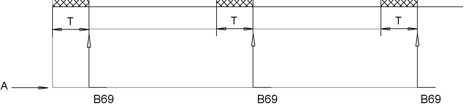
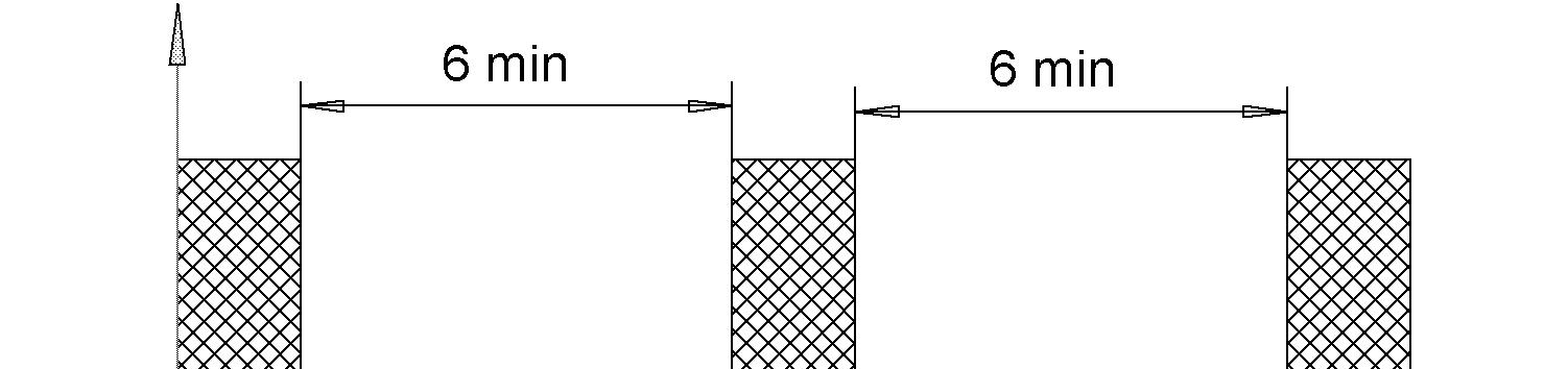
P1 with pressure control
Legend: T:running time
Pause time: 6min
A: pressurecontrol device
P1 safety mode, without pressure control
Legend: T:runningtime10sec –250 sec
Pause time: 4min-10min
A: timecontrol device, pressure switchoff
Legend:
D Pause time 5min – 15 min
T Runningtimefor one lubricationcycle
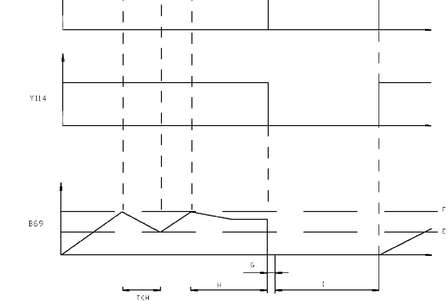
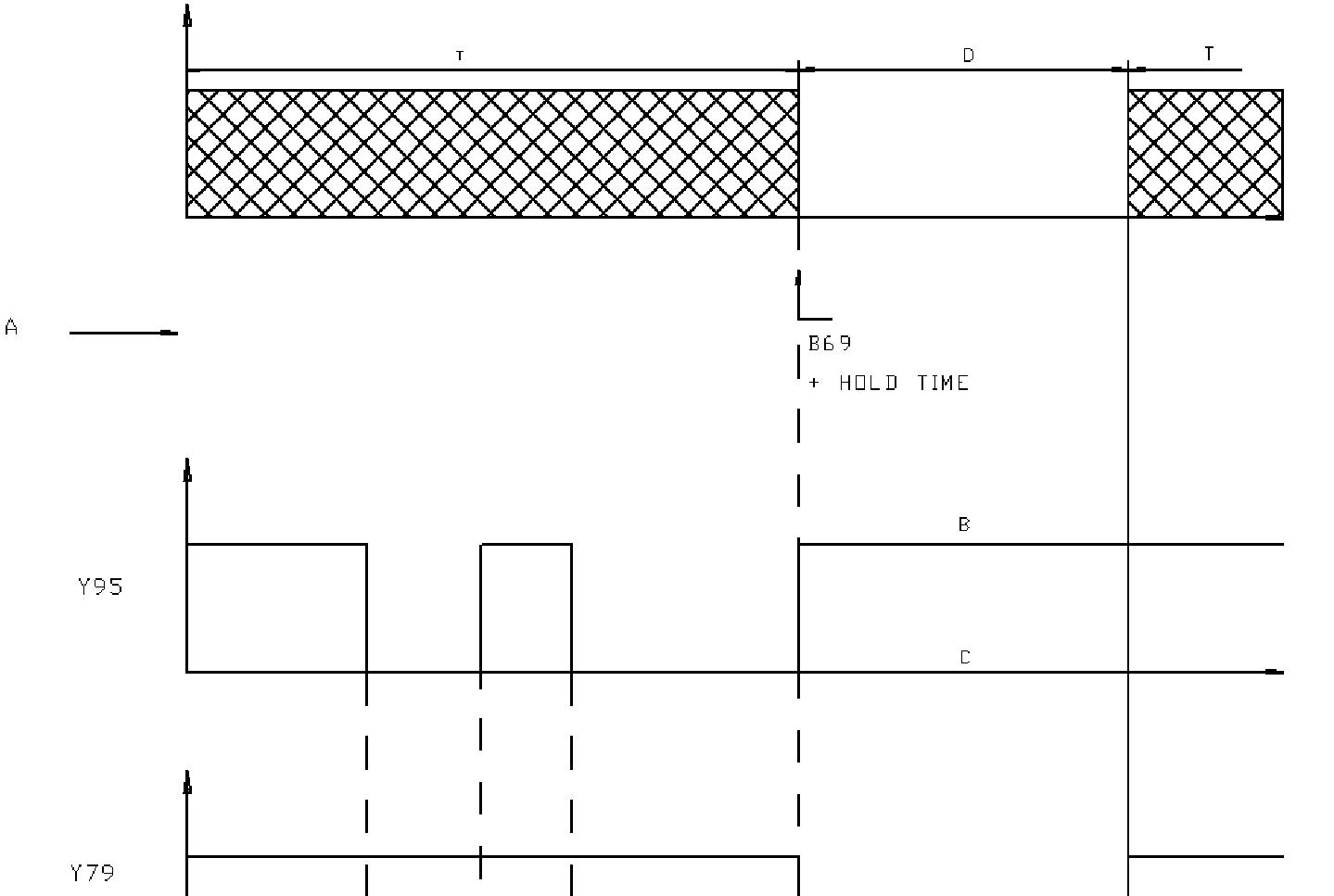
Y95 Pump
Y79 Dumpvalve
Y114 Valve
B69 GreasePressure
A Cycleends with maxpressureafter hold time
B Winter operation on
C Winteroperation off
E Max pressure– 40 bar
F Max pressure
G Tempo
H Holdtime
I Continous pumping (only with winter operation buttonon)
Fig.5
Cycle:Equipmentanduppercarriage
9.2.3 Single-linesystem
The single-line system consists of a pump to supply lubricant under pressure to the injector metering devices via the supplyline. Theinjector metering devices deliver lubricant to a secondary (progressive)metering device or to the bearing through feed lines.
The lubrication cycle is initiated by anautomated pump. The injectors have indicator stems, which move inandout to indicate that they have been cycled.
A controller will control theautomatedsystem.
The timebetween on cycles and the length of off cycles is adjustable. The controller includes the timer function above witha monitor function and alarmcapability.A pressure switchisused to indicate when system pressurehas been reached to turn off the pump and verifythat a lubecycle has been completed. If the pressure switch does notdetect fullpressure withina preset period of time, the controllergoes into alarmstate.
Forinformationanddescriptionsofthecomponents,refertochapter13.
* refer tothe user manual9.3EN-98002-xx(page 19)
9.3.5 Electronic Controller
Formore details:
Operating elements Functions
Refer to Manual 93EN-98002-A11_OpInst_LIEBHERR-LFR_Mining_664-36957-7_...
Faultsignals
Each timea fault arises, anacoustic signal will be given by the controller (buzzer)and thetwo flashing lights on thepumpstations willbe activated. Buzzer and flashing lightscan be deactivated by pressing the ENTERkey.
Intwocasesthis willnot be possible:
- very lowgrease level in the barrel (LL)
- both sensorsformonitoring the lubrication of the slewing rimaredefective
In these cases, buzzer and flashing lights will be deactivated when switching off the motor, however, will be activated again when startingthe motor.
Adjustedvalues
For service personnel withPC,correspondingsoftware and authorization: adjustable max. value adjustable min. value adjustedvalue
System P3: Swing ring and swing gear lubrication
IntheautomaticsystemP3,thecentrallubricationpumpprovideslubricanttotheProgressiveMetering Device (Progressive System) which distributes the lubricant to each lubrication point evenly (swing ring teeth andthe swinggear centering seat).
Grease cycle
When the pause time has lapsed, the pump P3 supplies lubricant to the connected progressive metering device. A progressivemetering device type SSV 6 is provided with the proximity switch B51 for control and monitoring purposes. After two cycles of the SSV 6, which correspond to a full lubrication cycle, the pump P3 is switched off thanks to the proximity switch B51.
1 Reservoir 15 liters
2 Level sensor
3 High level sensor “Full”
4 Overflow pipe
5 Pump housingwith integrated motor
The pump is a compact multiline pumpconsisting of the following components:
· Reservoir with stirring paddle
· Printed circuit board
· Pump element
· Pressurerelief valve
· Filling nipple
· Electrical connection parts
· Operates according to lubrication cycles (pauseand operatingtimes)
· Designed forthe deliveryof greases up to NLGI 2
· Can be used at lowtemperatures downto -40 °C.
· During the operating time the pump dispenses lubricant to the connected lubrication points via onedevice.
Numberof outlets: 1
Piston diameter: 7 mm
Lubricant output: approx.4 cm³/min
Reservoircapacity: 15 liters
Formore details:
Description
Modeof operation
Maintenance
Troubleshooting
Technical data
Refer to Technical Description: 21EN-30001-xxx; 20EN-20003-xxx; 26A-20003-xxx
Forinformation and descriptions ofthecomponents, refer to chapter 13.
10 Operation
Greasing system – Cabin Location
Formore details:
Information regarding the operation of thecontrol unit are availablein the respective manual.
Refer to Data Sheet 93EN-98002-xxx for the Electronic Controller
System P1: Automatic lubrication
CAUTION!
Operation by authorized andinstructed personnel only! Never exceed the admissible system pressures! Refillcleanlubricant on time!
CAUTION!
Donot interrupt the power supply(mainswitchof battery) while thepumpis operating.
When starting the excavator, the centralized lubrication systems are connected to the power supply automatically.Eachlubricationpumpthenstartsafulllubricationcycleandisstoppedduringthepreset pause timeonly, etc.
The pump P1delivers lubricant viaa single-line systemto the lubrication points according to Chapter 9.2 Configuration.
Regarding the control and monitoring of the system refer to: Chapter 9.2. Cabingreasing module U41 or ElectronicController
If required, the operatorcan force the greasing cycle: for detailsrefer to therespective data sheets.
Seethecharacteristicsofeachlubricationpoints:Characteristicsoflubricationpointsontheexcavator.
Formore details:
Chapter 9.2 Greasing cycle
Pump P3 CAUTION!
Operation by authorized andinstructed personnel only! Never exceed the admissible system pressures! Refillcleanlubricant on time!
CAUTION!
Donot interrupt the power supply(mainswitchof battery) while thepumpis operating.
When starting the excavator, the centralized lubrication systems are connected to the power supply automatically. The lubrication pump starts a full lubrication cycle and stops during the preset pause time only, etc.
The pausetime is factory-set to6 minutes.
In normalworking condition,no actions are required from the operator.
The only useful informationis thelowlevel quantity ofthe pump P3 reservoir.
If required, the operator can force the greasing cycle:for detailsrefer to therespectivedata sheets.
NOTE!
DAILY:DOA VISUAL CHECKOF THE RESERVOIR FORGREASE LEVEL
Formore details:
Chapter 9.3 Greasing cycle