6 minute read
Safety instructions


connect the upper structure to the chassis using stop bolts. experiencemayworkonhydraulicequipment.
tive gloves. A fine jet of liquid under pressure can penetrate the skin.
s before you have set aside the equipment, switched off the engine and depressurized the hydraulic system. After switching off the engine, with the start key in contact position and with the safety leverdowninto itslowestposition, you mustoperateall pilotcontrol devices (joystick and pedals) in all directions in order to reduce the actuating and dynamic pressures in the work circuits. You must then reduce the internal tank pressure as described in these operating instructions.
Electrical system
Have all faults, such as loose connections, blown fuses and lamps and clogged or abraded cables rectified by personnel.
e event of malfunctions in the power supply.
trical equipment may only be carried out by skilled electrical personnel or by trained personnel under the supervision of an electrician in accordance with electrical regulations.
a second person is available to operate the emergency-off or the main switch and overvoltage release. Cordon off the working area with a red and white safety chain and a warning sign. Only use insulated tools.
voltage, briefly disconnect the supply cable at earth and electronic devices such as capacitors using an earthing rod.
that they areoff circuit, earth them and then disconnect them briefly. Insulate adjacent live parts.
electric arc welding on the machine. Firstdisconnectthenegative,thenthepositivepole.Whenreconnecting,proceed in the reverse order.
Hydraulic accumulator
personnel.
licaccumulatorscancauseseriousaccidents.
hydraulic system (hydraulic system including hydraulic tank), as described in these operating instructions. accumulator.
The hydraulic accumulator can be damaged by heat penetration and can be made to rupture by mechanical working. RISK OF EXPLOSION!
copyright © Liebherr-Mining Equipment Colmar SAS 2021 accumulatorwithnitrogen.ThereisaRISKOFEXPLOSION if oxygen or air is used. purpose of use before installation. on hydraulic accumulators. Ensure that this marking remains visible.
Hydraulic lines and hoses
becheckedregularlyforexternallyvisibledamageandanypossibledamagemustbeimmediatelycheckedforleakage. else.
ately!Spurting oil can leadtoinjury and burns.
natural aging process. This restricts their duration of use.
common causes of failure.
tnorms,regulationsandguidelinespertaining to lines and hoses at place of use must be adhered to.
adcanshortendurationof use(e.g.high temperatures, frequent movement cycles, extremely high pulse frequencies, multiple shift usage).
the natural form of the line or hose, whether in a unpressurized or pressurized state or on bends e.g. sheath separation, blistering; fittings or the hose / fitting connection; out of the fittings; reduces function and tightness; pressure hoses, the screws from the half-clamps or full flange must always be attached to both hose ends and should only be tightened afterwards. ssure lines and hoses with bent fittings, thesidewiththebentfittingmustalwaysbetightenedfirstandthenthesidewith the straight fitting tightened afterwards. attached and tightened subsequently. covers and protective devices are properly fastened. Doing this will prevent vibration and damage during operation. hoses or parts. prox.halftheexteriordiameterofthe hose is recommended. The distance should not, however, be less than 10 to
Safety information for electrical system stick), check before initial start-up that there are no chafing areas in the entire area of movement.
15mm.
Disposal
Disposal of the machine after the service life in accordance with all applicable national, regional or local regulations for waste disposal and environmental protection.
Disposal of gas tanks and pressurized tanks tank manufacturer for disposal.
Disposal of fuel, lubricants, operating fluids and consumables tingfluids inapplicable containersbefore disposal. disposed of in an applicable recycling point. trained air-conditioning and refrigeration technician. ts andoperating fluids manufacturer for disposal.
2.5Safety information for electrical system
regulationinthemanualissuedbythe supplier of the electrical box installation.
opened, serviced or repaired, it can be done only by authorized andqualified personnel! Alllocallaws and requirements must be strictly adhered to.
plantmustensuretheirownsafety and the safety of other persons working on the machine by locking the machine out thedutyoftheresponsibleoftheexcavaof all people adequate tools and adapted safe work procedures.
repair/maintenancejobonelectricsystem to avoid electrical shocks: local electric regulations. machine. ectrician is required to assist the electrician supervisor. ke a power lock and tag out according to all local electric requirements and procedures. eventinjuriescausedbythepresenceof voltage, and by the machine starting up or moving unexpectedly. These proceduresmustbefollowedeverytimeamachineisgoingtobecleaned,maintained, or repaired. ectrical box / leakage in hydraulic rotary connection, replacing tracks or making repairs, or any other maintenance task on electric plant or at proximity, safe and effective lockout practices will protectyourlife.Alwaysfollowtheexactprocedureforthevoltagelevelyouareworking on and do not take chances! cedures. This will protect their life.
Danger!
High voltageis still present on the excavator upto the main breaker 6kVwhen the machine is in standby by pushing button 6kV OFF from the cab. ALL ELECTRIC WIRES AND BOXES mountedon upper/undercarriage must be considered under voltage.
To disconnect totally the excavator, proceed with a lock and tag out procedure at the power station as follows: Locate power station supply and distribution. Stop excavator, disconnect excavator from the network at field switch. Check voltage presence on excavator supply line. Earth and short-cut the supply line. Lockout and tag out at field switch.
Open S1 and use the lever on the inside to earth the uppercarriage. Close S1 and keep key in a safe place.
Always use adapted tools suitable for the voltage.
Workplacesshouldhaveawrittenlockoutprocedureforeachmachine,depending on your country, outlining:
A Safe Work Procedure has been developed by Liebherr-Mining Equipment ColmarSASforitselectricianpersonnelworkingonelectric plantofanelectricmachine. This document is available in the Service Manual for information and must be adapted to your local electric regulations and procedures.
Someelectriccomponents(suchashighvoltagesupplycable,transformers,motor windings...)storesomeresidualelectricpower.Beforeworkingonelectriccircuitincluding such components, you must discharge these components to the earth.
Concerning work with voltage on electricsystem, Liebherr-Mining Equipment Colmar SAS recommends to lock and tag out (power OFF) at the supply station or at thefieldswitch in case of any maintenance or work on electric risks areas. People must be trained and certified from their employer according to the electrical local regulations.
Safety instructions
Safety guidelines to connect and start-up this electric machine
Danger!
Never cross the extern limit distance of Danger Area with any tools or any body parts. The approach area can only be considered as the working area, in order to measure the voltage or check voltage presence. The area must be roped and tagged. Parts under voltage should be protected to avoid any electrifying.
Thefollowingfigureillustrates thedanger area A andtheapproacharea Baround ariesDL andDV).Alwaysobservelocalregulationsconcerningtheseareasaccording to the country you are working in.
Any job/maintenance at proximity of voltage must be done with all safety requirements presented in this ma THERE ARE NO SHORT CUTS IN SAFETY!
2.6Safetyguidelinestoconnectandstart-upthis electric machine
When connecting this machine to an electrical power source, as well as during the initial start-up, the following instructions and safety guidelines must be adhered to : all pertaining local, state and national standards, safety guideline, rules and regulations (such as ANSI, CIMA, DIN, IEC, INRS, ISO, NEC, NEMA, NF, OSHA, SAE, UL, VBG, VDE, EN, UTE, etc...) must be adhered to at all times. stallation, particularly connecting the machine to an outside power source and the start-up procedure must be performed bya qualified and certified personnel. operly protected againstover-voltageand excessive current draw, short circuits and faulty ground. be switched off at the first fault (insulation, overcurrent, overload or ground fault) and this fault must be solved. m or component damage, the supply voltage of all three phase conductors must be nearly the same (equal). wire must be of sufficient gauge (cross
Signs on the machine section). cured and all fasteners and contacts must be clean and properly connected. ape and in goodcondition. Undervoltage, they have to be carried with insulated gloves 6kV. moved. Immediately replace illegible, damaged or missing safety signs and decals.
These signs warn of electrical hazards. Proper precautions, attention and procedures are required to prevent accidental injury or death.
DANGER HIGH VOLTAGE
DANGER SUPPLY LINES FROM BELLOW ARE UNDER VOLTAGE
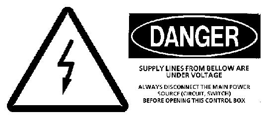
Never touch any electrical component under voltage. Always disconnect the main power source (circuit) before commencing with repairs.
Never touch any electrical component under voltage. Always disconnect the main power source (circuit) before commencing with repairs.
2.7Signs on the machine
2.7.1Introduction
The excavator comprises several types of signs: the safety plates provide warnings relating to dangers of accidents which could result in serious injury or death.
the information plates indicate specific points relating to the operation, maintenance and characteristics of the machine.
the nameplates are attached to components for which the machine serial number must be provided when ordering spare parts.
Danger!
Non-observance of safety plates can result in serious injury or death. Checkwarningplatesregularlytoensurethattheyarecompleteandclearlylegible.
Replacemissingor illegiblesafety andinformationplatesimmediately.Youwill findtheorderingnumbersof theseplatesinthe sparepartsbook oftheexcavator.
2.7.2Arrangement of signs
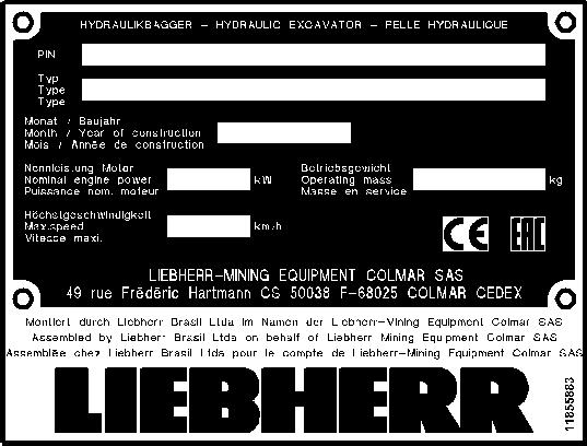
Plate1:TypeplateLEC(Liebherr-MiningEquipmentColmarSAS)"CE"/"EAC"
This typeplate displays the following information:
Plate 2: Typeplate LEC (Liebherr-Mining Equipment Colmar SAS) This typeplate displays the following information:


Plate 3: Typeplate LAM (Liebherr America)

This typeplate gives the following information:
Plate 4:Typeplate LBR (Liebherr Brazil) "CE" / "EAC"
This typeplate gives the following information:
Plate 5: Typeplate LBR (Liebherr Brazil)
This typeplate gives the following information:
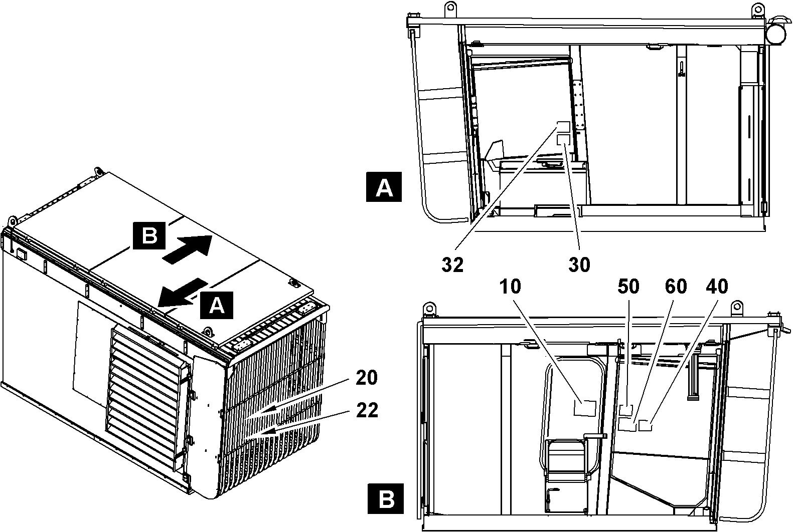
Plate 10: Lubricating chart label Indicates the different fluid change and analysis intervals to observe.
Plate 20: Operating manual label Indicates that the informations in the Operating manual must be carefully noted.
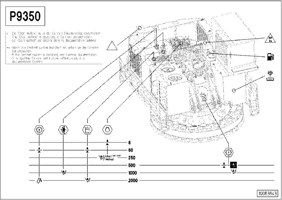
Plate 22: External starting label Indicates precautions to be taken before removing starting cables.
Plate 30: Hydraulic tank shut-off valves label Indicates precautions to be taken beforestarting the excavator.
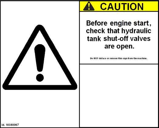
Plate 32: Safety belt label Indicates to always seat belt while operating the excavator.
Plate 40: Safety lever label Indicates precaution to be taken before leaving the driver seat.