8 minute read
Control and operation


Thecurrentoperatinghourwillbeconfirmedasthelastserviceintervalcarried out.
Service work not carried out.
Press the Back button. The submenu will be aborted.
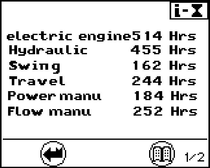
Allocation of quantity limitation options to external input I1 menu
(Kit input; for example, activation of the hammer pedal)
Predefined quantity limitations have been assigned in this menu. The arrow opposite the symbol represents the current selection.
In theexample(see Fig. 3-15), quantity 2 is activeifthespecifiedattachment is serviced.
Fig. 3-15 Work equipment quantity limitation menu
Press the Up or Down arrow key. A different, predefinedquantity (1-4) can beassigned(e g.whenwork equipment is changed).
Press the Menu button. The selection is confirmed. The arrow displays the current selection.
To exit the menu: Press the Back button. The submenu will be aborted.
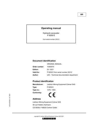
Operating hours menu
Page 1 provides an overview of the operating hours of individual units, processes and operating types.
Page 1 provides the service life in hours for:
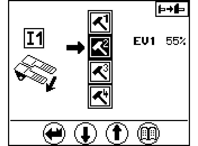
Fig. 3-17 Technical data

Press the Menu button again. Page 2 is displayed. The technical data menu, page 3, provides information on : l which is currently built in (ver)
Press the Menu button again. Page 1 is displayed.
To exit the menu: Press the Back button. The submenu will be aborted.
Status ofhydraulic pumps and electrical inputs and outputs menu
Fig. 3-18 Quantity limitation menu
Press the Menu button again. Page 1 is shown.
This screengives information about the operatingpositionofthehydraulic pumps.It gives the following indications for each working pumps:
Iftheflowlimitationisactivatedforthepump.Ifitoccurs,thesymbol"R"isshown in the field TI, refer to main screen. The screen 1/6 shows an example with the flow limitation M1 activated, which limits the pump P2 to 34% of the maximum flow. If several flow limitations are actuated at the same time, the one with the smallest flow value has priority.
The graphic bar with electric current value indicates for the pump the amount of the momentary flow control signal.
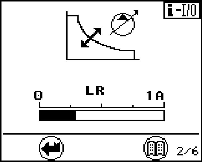
Press the Menu button again. Page 2 is shown.
The present LR current (current value for power control) is shown on screen 2.
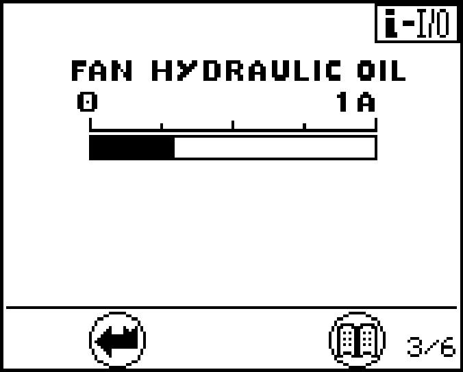
Press the Menu button again. Page 3 is displayed.
Thescreen3showsforthefanpumpsthequantityofthemomentaryflowcontrolsignal.
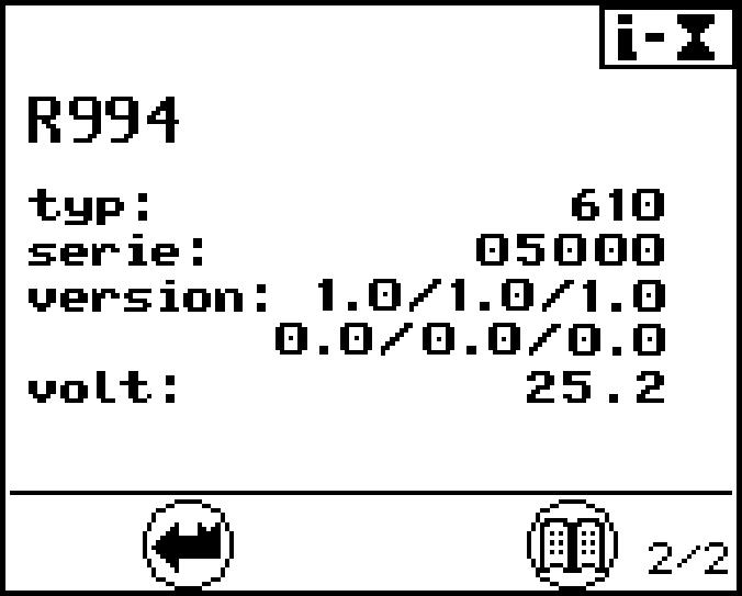
Fig. 3-21 Electrical inputs
Press the Menu button again. Page 4 is shown. Press the Menu button again. Page 5 is shown.
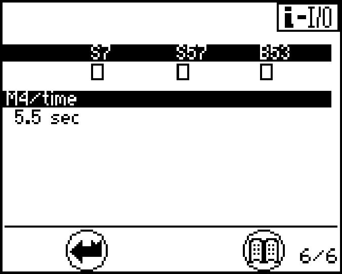
Press the Menu button again. Page 6 is shown.
Pages 4, 5 and 6 provide an overview of the status of different electrical inputs.
means that the software for the relevant input has been deactivated.
The status of the inputs can be changed using the menu "set data" - "set E-code".
The screen 4 shows the status of the inputs for the different movements.
The screen 5 shows the status of the flow limitation. M1, M2, ... correspond to machinespecific(internal)oilflow limitations.I1,I2,...correspondtopredefinedoil flow limitations (see also menu "set option").
Thescreen6 shows the status otherinputs.For thefrequency inputs B53,thesigns .
B53 Swing motor sensor
S7 Safety lever servo control
To exit the menu: Press the Back button. The submenu will be aborted.
S57 Swing brake
Error menu (operating errorsand electrical system errors) list S-Exxx, all errors which appeared when the service connector was connected are listed.
There are 3 selection options in this menu: list Exxx, machine errors recorded by the sensors are listed. list E-elec, all main screen cable errors stored when operating are listed.

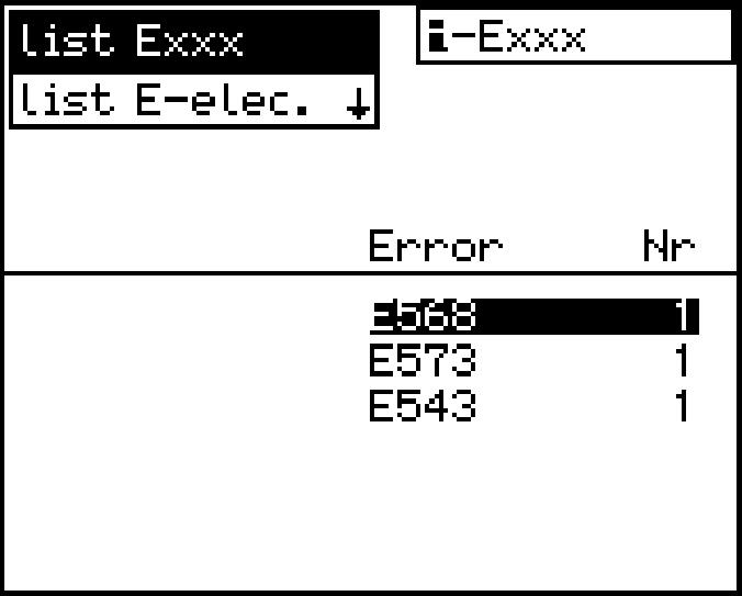
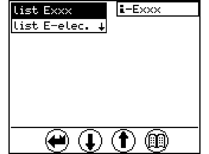
To select the desired error type: Press the Down or Up arrow key. The following or preceding error type will be displayed with a black background.
Press the Menu button. The submenu on a black background will be displayed. Ifmorethan6errorcodesarepresent,arrowkeyDownorUpcanbeusedto scroll to the next page.
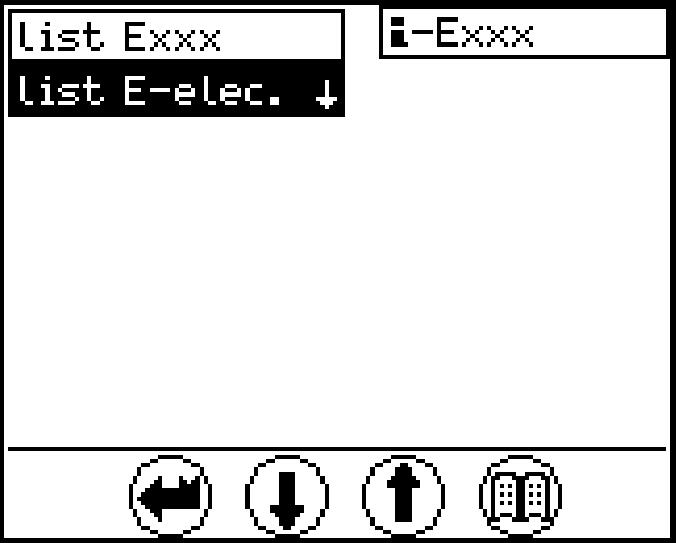
Machine error list Exxx:
Select list Exxx
Press the Menu button. The first page of the submenu is shown. All errors and their error codes are listed on the first page. Use the Down or Up arrow key to select the error code desired. Press the Menu button again.
The second page of the submenu is shown.
Operatinghoursandthedurationofthefirstandlasttenoccurrencesoftheerrorse- lected will be listed on the second page. s*: Error was indicated by a buzzer and was acknowledged using the Back button. The duration is given in seconds. m*: Error was indicated by a buzzer and was acknowledged using the Back button. The duration is given in minutes.
Press the Back button. The first page of the submenu is shown.
PresstheBackbuttonagaintoselectanothererrortypeorpresstheDownorUp arrow key to select a new error code.
Note!
OnlyoperatingerrorswithanerrorcodeE5xxwillbeshowninthelistExxxmenu.
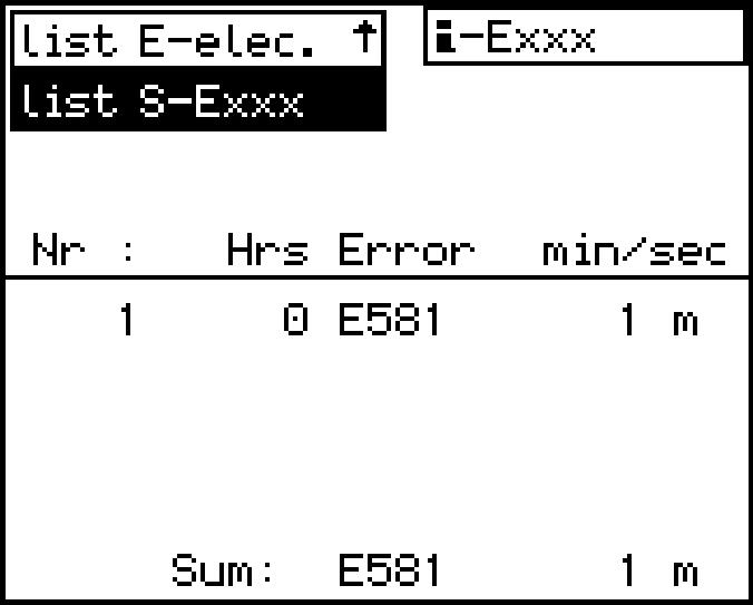
Cable error list E-elec.:
Fig. 3-24 Occurrence of electrical error (Fig. left) and Error statistics (Fig. right)
Select Cable error listE-elec.:
Press the Menu button. The submenu appears.
The column "Sum" shows the number of all errors that were ever noted.
The column "Test" shows the number of errors which have occurred since the last deletion of this test error memory listing.

The operating hours above the test column show the operating hour when the last test memory was deleted (reset).
Press the Back button.
A different error type may be selected.
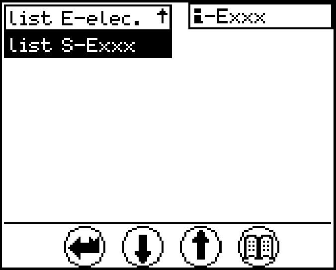
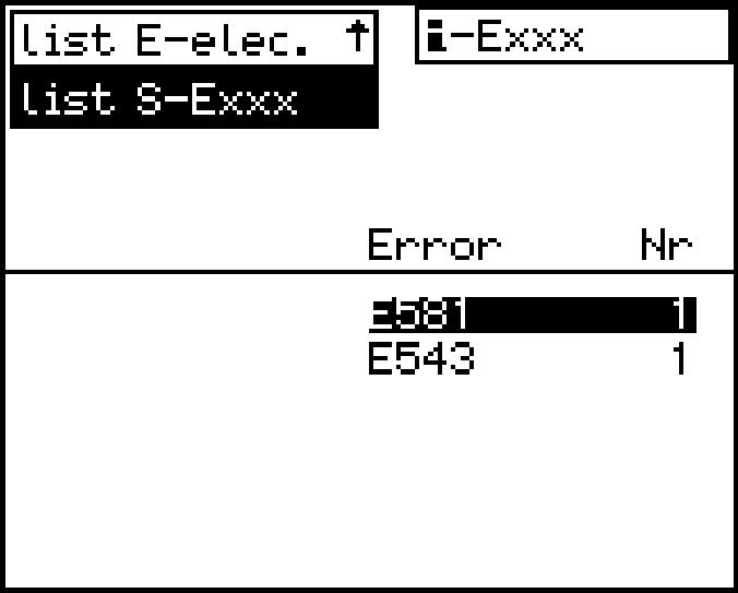
Other errors list S-Exxx:
Call up service operation error list menu
Selecting "list S-Exxx" also shows the errors according to the list in pages (refer to section "Warning symbols inthe SY field", but this time only theerrors that occurred during "service operation".
For each error, an overview can be shown and paged in just like for the "list-Exxx" selection. The column "Sum" shows the number of all errors that were ever noted.
3.2The access and the outfit of the cab
Safely getting up
chine on even, horizontal ground. The upper structure should be positioned with the undercarriage in such a way that the steps and ladders are aligned with each other.
(grips)areingoodcondition.Inparticular, you should ensure that they are free of dirt, oil, ice and snow.
NOTE:Toensurethatthedoorsopenproperlyinallweatherconditions,thedoor seals must be dusted with talc or silicon at least every two months or more often if required. The door hinges and locks should be greased regularly.
two hands and one foot or two feet and one hand must always be in contact with the access system at the same time.
fore you climb any higher. External influences, such as wind, can make it more difficult to open doors. Because of this, always use your hand for control when opening doors. Ensure that the door is latchedopen to prevent it slamming open and shut.
icularly vigilant to realise the climbing and descent from the cab with the best safety conditions, and do or give the instructionstotheexecutionofpriorpreparations tobeaccomplished,asenunciated above, in order to displace yourself safely.
still using the three-point support andsit downinthe and close it immediately using the door handle, before tilting down the safety lever, and start the machine. necessarytofastenyoursafetybelt. If unavailable, let it be installed before working with the door open. e three-point support and close the door assoon as you enter the cab. thesafetybelt(ifavailable)beforetilting down the safety lever, and start the machine.
Safely getting down
b up or down onto the machine, as to install yourself.
sitioned with the undercarriage in such a way that the steps and ladders are aligned with each other.
Unfasten the safety belt.
three-point support, i.e. two hands and one foot or two feet and one hand must always be in contact with the access system at the same time. Climb down until youcanclosethedoorssafely.Alwaysuseyourhandforcontrolwhenclosingthe doors. Lock the door.
3.2.1Enter or leave the cab Climb up Caution!
Entering or leaving the cab incorrectly could lead to injury.
Proceedwiththesameattentiononexitorentryofthecab,aswhileclimbingthe machine.
Ensure that the safety lever is always in its highest position when entering or leaving the cab.
Alwaysusethehandholdsprovidedforthepurposewhenenteringorleavingthe machine.
Facethemachinewhengettinginoroutandalwaysusethree-pointsupport,i.e. twohandsandonefootortwofeetandonehandmustalwaysbeincontactwith the access system at the same time.
Never use the control elements as handles. Never jump from the machine.
Get in
If the excavator is not running, you can climb up on the machine. Climbinwiththeaccessladdersandwithyourfacetowards theladdersanduse the provided handholds. On the cabin catwalk, open the door.
Adjust the seat if necessary.
Get out
Switch off the machine and pushthe safety lever up. Open the door fully.
Go out of the cabin on the cabin catwalk.
Close the door.
Godownwithyourfacetowards theladders,andusetheappropriatehandholds.
3.2.2Safety lever
For safety purposes, the left control panel is provided with a safety lever.
Caution!
The safety lever must always be pushed up into its highest position (see arrow) when entering or exiting the cab.

When the safety lever is pushed up, the pilot control circuit is disconnected. This means that: when pilot control devices, eg. the joystick or foot pedals, are operated.
S17 illuminates).
S17
When the safety lever is pushed (push up / push down) to its lowest position, the slewing gear brake and the LED in switch S17 will return to their original states and the pilot control devices will be active.
Before the operator starts working, he must push the safety lever down into its
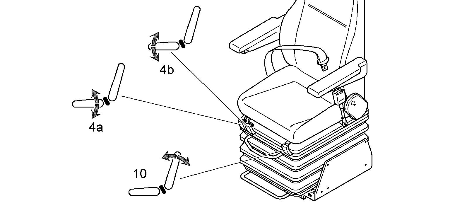
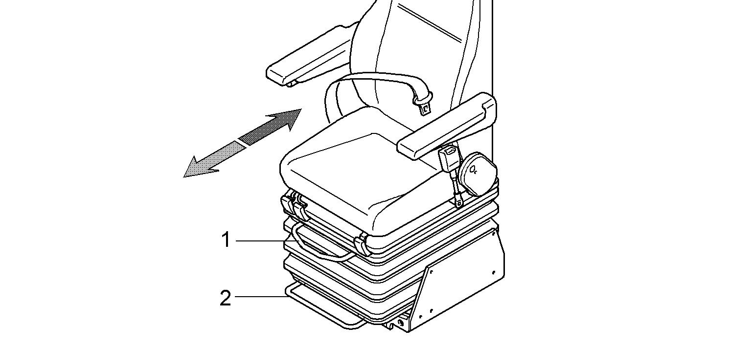
3.2.3Operator’s seat
1 Set horizontal, upper 4a Set seat inclination, front 7 Set lumbar support
2 Set horizontal, lower 4b Set seat inclination, rear 8 Seat heating

3 Adjust armrests 6 Set lumbar support 10 Set backrest
This will avoid unexpected movement of the machine.
Setting the armrests
Turn the knurled head screw 3 on the armrest in direction a The armrests incline upwards.
Turn the knurled head screw 3 on the armrest in direction b. The armrests incline downwards.
Setting the seat and backrest
Rear seat inclination: Pull lever 4a up, set the inclination and release the lever. Front seat inclination: Pull lever 4b up, set the inclination and release the lever.
Backrest: Pull lever 10 up, set the inclination and release the lever.
Setting the horizontal seat position
Pull up the lever 1 to push the operator's seat in the horizontal direction. Pullupthelever2topushtheoperator'sseatandcontrolpanelsinthehorizontal direction.
Setting the vibration damping and lumbar support, switching on theseat heating (air-cushioned operator’s seat, optional extras)
To set the vibration damping:
Press button 5 (+ or -) and set the vibration system according to body weight.
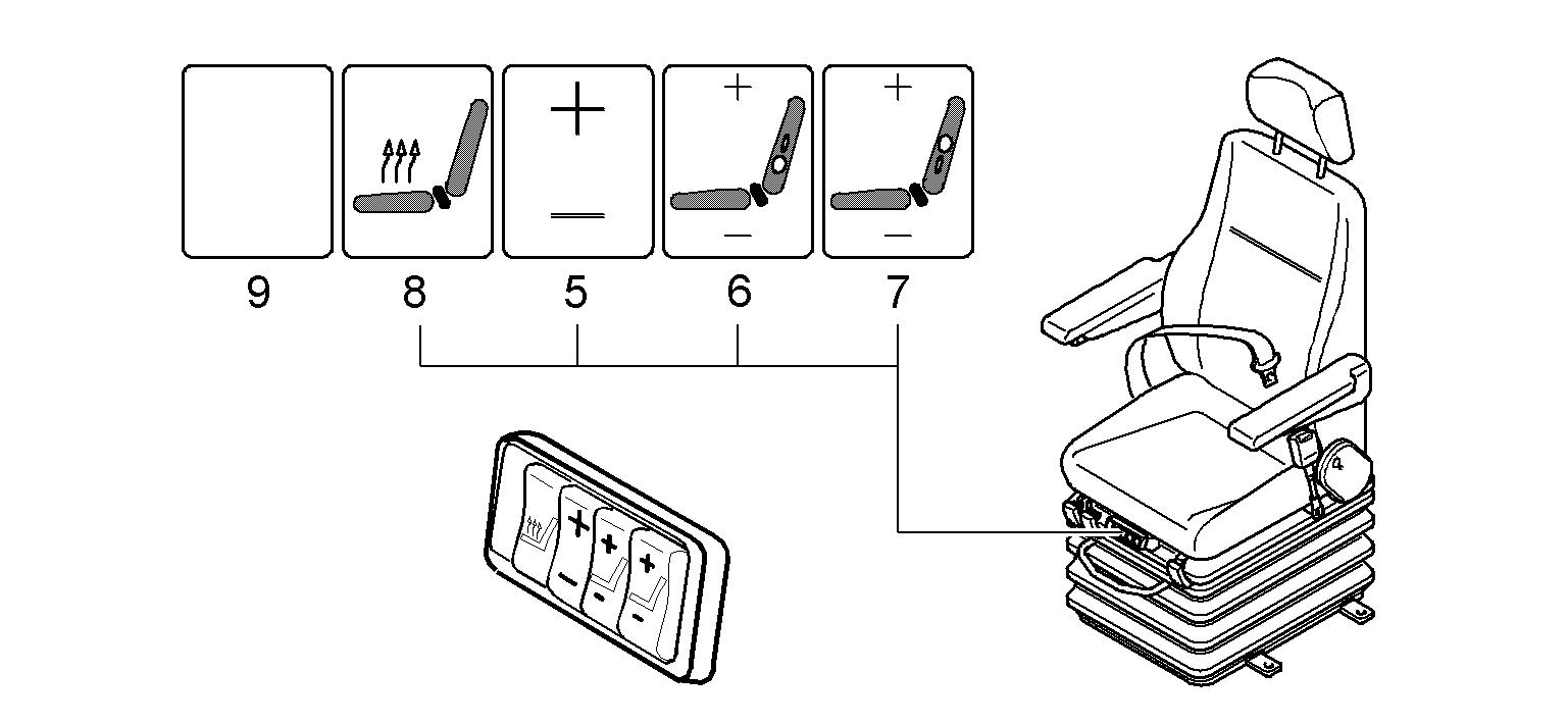
To set the lumbar support:
Press button 6 (+ or -) to inflate or deflate the lower lumbar chamber.
Press button 7 (+ or -) to inflate or deflate the upper lumbar chamber.
To set the seat heating:
Use switch 8 toswitch the seat heating on or off.
The seat heating switches off automatically when the temperature set is reached.
Putting on / releasing the safety belt
Fig. 3-33 Safety belt
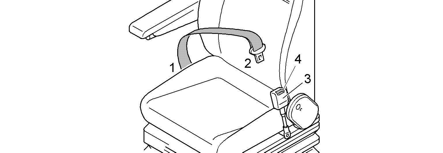
The safety belt is automatic. It is not necessary to adjust the length of the belt. Pull the belt and buckle 2 out of the roller mount 1 If pulled out of the roller mount sharply, the belt may lock. Push the buckle into the belt lock 3 until it fastens.
Danger!
The safety belt is designed to protect the operator. Before starting the machine, always fasten the safety belt. Ensure that the safety belt is not twisted when it is fastened. To ensure your safety, check the condition, function and fastening of the belt regularly and replace any damaged parts without delay.
To open lock 4, push down on the belt lock using your thumbs. The safety belt will slide automatically back into the roller mount 1
3.2.4Adjusting of the auxiliary seat
3-34 Auxiliary seat
Thelever1serves tolock the auxiliaryseat into
The access and the outfit of the cab
To rotate the seat, Pull the lever 1
To seat, Pull down the seating.
Note
When there is no oneon this auxiliary seat, the seating must be pulled up andthe
3.2.5Sunshade
Windscreen
Pull the sunshade down using the cross strut on the sunshade 1 The sunshade can be set for individual use.
Pull out on the string 2
The sunshade rolls itself up.
Side windows
Pull the sunshade down using the cross strut on the sunshade 1 The sunshade can be set for individual use.
Pull out on the string 2.
The sunshade rolls itself up.
3.2.6Emergency exit
Rear emergency exit (if installed)
Danger!
Incorrect use of the emergency exit! Risk of death.
Youcanusethewindowatthebottomofthecabdoorasanemergencyexitonly if this window has an emergency handle.
Ifthewindowatthebottomofthecabdoordoesnothaveanemergencyhandle, use the lateral emergency exit (refer to the description below).
1
To open the emergency exit: Pulltheemergencyhandle1 ontheinsideofthewindowwhichisinstalledatthe bottom of the cab door.
The window seal breaks into two parts and the window is released. Push the window out.