17 minute read
5.6Condition monitoring with oil analysis


5.6.1General information
Oil analysis helps to monitor the main components condition by observing oil chemical and physical properties which can show either the oil contamination by foreign orwear particles, or the degradation of its properties.
Component oil analysis in accordance with the recommended procedures, intervals and specifications and the records of a component oil analysis are strongly recommended because this will support any warranty claim raised upon LIEBHERR.
Bycomparingtheoilpropertiesandcontaminantstoreferencelevelsandevenmore byobservingtheirtrendsoveraperiodofoperation,itispossibletooptimizethecomponent lifetime, possibly to prevent further damage (preventive exchange) and potentially to reduce rebuild and maintenance costs.
An oil analysis will give an indication of the component condition. But the measured valuesandtheirtrendoveraperiodofoperationneedalwaystobeinterpretedinrelation to the machine operating conditions and to events such as services, top-up, component change-out, etc.
Theinterpretationoftheanalysisresultsneedalsotobecomparedtosamplesofthe new oil. Therefore, newoilneedstobeanalysedtwiceayearandwhen changingto another oil supplier.
This procedure is applicable for these components:
These parameters must be monitored:
5.6.2Oil sampling
Sampling intervals chart.
, Mg, B, Zn, P, Ba or S) the used oil immediately before draining it. plier.
Sampling instructions
General sampling instructions: Wear personal protective equipment. Get the sample:
Clean the area around the sampling point before you get the sample. Use an appropriate sampling kit. Keepthesamplingmaterialawayfromhumidityanddust.Taketheseprecautions to choose a storage area.
Make sure the sampling material is perfectly clean (without dust, water, fuel...). If different sampling procedures are applicable for a component, always use the same sampling point and the same sampling procedure for this component to make sure that the analysis records stay relevant.
Fill the sampling bottle with oil to 80% level. Do not fill the sampling bottle to the top.
Close the sampling bottle tightly to ensure the integrity of the sample. Identify the sample with a label.
Carefullyfillinasampleinformationsheet.Inanycase,itismandatorytogivethis information with the sample:
Send the sample in oil-proof adapted material. Check fortherequiredsampledelivery timeandforsample export licence(ifthe laboratory is located out of the country, make sure that the export of the sample is authorized from your location to the laboratory).
Do not wait before sending the sample to the laboratory. Record and save sampling operations and results.
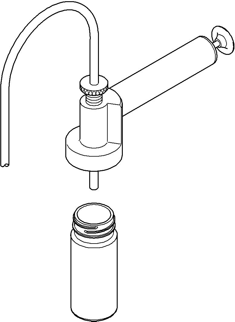
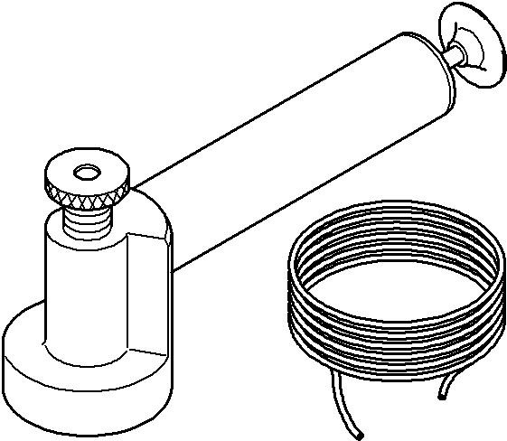
If you get the oil sample with a sampling pump:
Use a sampling pump if you get the sample directly in the tank or on the component (machine stopped).
Always use a new sampling hose.
Cut the sampling hose to the correct length (e.g. dipstick length plus 20 mm).
First, let sufficient oil flow to flush the sampling hose.
If you get the oil sample in the tank, take the sample in the middle of the tank.
If you get the oil sample through a sampling valve:
Always use a new sampling hose.
First, let sufficient oil flow to flush the sampling hose. Gettheoilsampleinthemid-stream,i.e.firstletasmallamountofoilflowthrough the valve before sampling it.
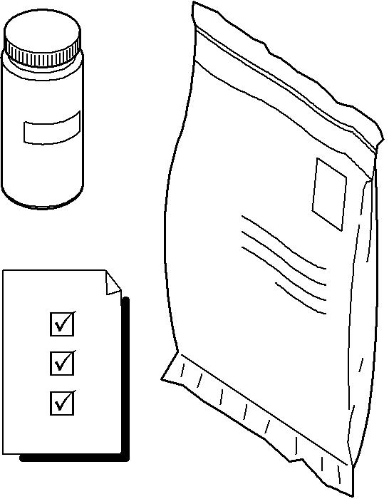
Sampling material
You can order LIEBHERR approved sampling material to get the samples: Note! These sampling kits are prepaid kits and include the cost of the analysis.
Before ordering these sampling kits, check for sample export licence: make sure that the export of the sample is authorized from your location to Europe.
To get a sample of the splitterbox oil:
Note!
Two sampling procedures are applicable for this component. Always use the same sampling point and the same sampling procedure for this component to make sure that the analysis records stay relevant.
Use the sampling valve 1 which is installed next to the splitterbox. or
Useasamplingpumpandgettheoilsamplethroughthedipsticktubeofthesplitterbox.
Hydraulic oil
To get a sample of the hydraulic oil: Use the sampling valve 1 which is installed on the suction pipe.
5.6.3Sample processing Analysis standards
LIEBHERRrecommendstosubmittheoilsamplestoOELCHECKGmbHforoilanalysis.
Ifanotherlaboratoryisused,theoilanalysismustbedoneaccordingtothesestandards:
Action level values
These tables give the action level values for the different monitored parameters for each component and the action to be taken if the action level value is reached. These values are applicable for mineral and synthetic oils.
Caution!
If three analyses one after the other give out-of-range results: Contact LIEBHERR Customer Service with the related analysis records.
Caution!
Comments and recommendations given by the laboratory on the analysis report must also be taken into account.
Splitterbox
ComponentParameterAction
Action
Iron level100 ppmChange oil (get a sample again after 250hours).
Copper level10 ppmChange oil (get a sample again after 250hours).
Silicon level20 ppmCheck component for entrance of dust (sealing, breathers...).
Splitterbox
Flush and change oil (get a sample again after 250hours).
Water content0,10%Change oil (get a sample again after 250hours). Viscosity
(*) Difference compared to new oil value.
Swing gear
ComponentParameterAction level value
Action
Iron level400 ppmChange oil (get a sample again after 250hours).
Copper level150 ppmChange oil (get a sample again after 250hours).
Silicon level15 ppmCheck component for entrance of dust (sealing, breathers...).
Swing gear
Flush and change oil (get a sample again after 250hours).
Water content0,10%Change oil (get a sample again after 250hours).
Viscosity change (at 40°C and 100°C)
<15%(*) Change oil (get a sample again after 250hours).
Additives change±20%(*) Change oil (get a sample again after 250hours).
(*) Difference compared to new oil value.
Hydraulic oil
Action
Silicon level15 ppmCheck for entrance of dust (cylinders, breathers...) (get a sample again after 250hours).
Viscosity change (at 40°C and 100°C)
<15%(*) Change oil (get a sample again after 250hours).
Water content0,10%1. If the machine has a bypass filter element with water separator installed, replace the filter. you get a satisfactory range.
2. Get a sample again after 250hours. If the results are still out-of-range: factory range.
Hydraulic oil
Particle Quantification (PQ Index)
501. Change the return filters, pilot oil filters, leak oil filters and replenishing filters.
2. Get a sample again after 250hours. If the results are still out-of-range: < 20 or less.
Cleanliness level (ISO 4406)
21/19/161. Change the return filters, pilot oil filters, leak oil filters and replenishing filters.
2. Get a sample again after 250hours. If the results are still out-of-range: inant code 20/18/15 or less.
(*)
5.7Electric motor
Refer to the Manual of safety, installation and maintenance of the electric motor manufacturer for detailed description of maintenance work to be performed. In addition, accurately observe the following items and perform all maintenance workaccordingtotheintervalsgiven in thecontrolandmaintenancechart(chapter 5).
5.7.1Mounting screws
Torque
1 Hexagonal head screw M20x130560 Nm
2 Hexagonal head screw M16x80280 Nm
3 Socket head screw M16x110280 Nm
Check the mounting screws on the motor brackets and the motor gear mounts regularly for tightness, retorque if necessary.
For maintenance intervals, refer to Control and maintenance chart. Any improperfasteningwouldgreatlyreducetheexpectedlifeof therubbermounts.
Caution!
Loctite nr. 243 must be applied on mounting screws 1, 2 and 3 when installing in order to avoid possible damages on the parts.
The screws 1, 2 and 3 must only be tightened after the electric motor and the splitterbox has beenpositioned on the uppercarriage structure as a complete unit, to avoid a pretentioning of the rubber mounting.
5.7.2Elastic bedding
The two rubber buffers 4 at the front face of the motor must be checked and replaced at regular intervals. For maintenance intervals, refer to Control and maintenance chart.
5.8Splitterbox
5.8.1Splitterbox mounting screws
Any incorrect fastening can decrease very much the expected life of the rubber mounts.
Checkthemountingscrewsonthesplitterboxbracketsregularlyfortightness,retorque if necessary.
For maintenance intervals, see control and maintenance chart.
Caution!
Loctite nr. 243 must be applied on mounting screws 1, 2 and 3 when installing in order to avoid possible damages on the parts.
The screws 1, 2 and 3 must only be tightened after the electric motor and the splitterbox has been positioned on the uppercarriage structure as a complete unit, to avoid a pretentioning of the rubber mounting.
Torque
1 Hexagonal head screw M12x90117 Nm
Checkthetightnessofmountingscrews1fromthesplitterboxtotheelectricmotor housing regularly, retorque if necessary. For maintenance intervals, see control and maintenance chart.
5.8.2Elastic bedding
Thetworubberbuffers1 atthesplitterboxsidemustbecheckedandreplacedat regular intervals.
For maintenance intervals, see control and maintenance chart.
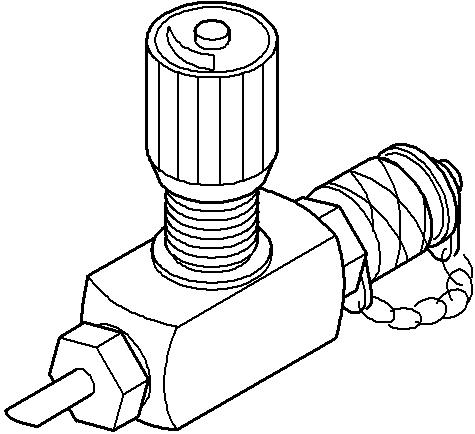
5.8.3Breather filter
The breather filter 1 on the splitterbox must be checked, cleaned and replaced regularly.
To clean the breather filter:
Open breather filter 1 by pushing it and turning it 1/4 turn. Remove the filter element 2 from the breather housing. Check filter condition and clean it with fuel.
Reinstall the filter element in the breather housing. Close breather 1
For check, clean and change intervals, see maintenance and control chart.
5.9Hydraulic system
Maintenance work onthehydraulic system isrestricted mainly to thehydraulic tank. All otherunits on the system do not require any special maintenance. Obey the intervals given to: turn-line filter
5.9.1Preparatory activities
Checkor adjust theoil level
Reset the attachment on the pontoon deck, with stick and tilt cylinders fully extended and bucket closed. Stop the electric motor.
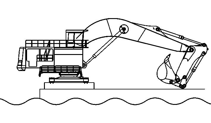
5.9.2Check theoil level in the hydraulic tank
When the machine is in the check position, the oil level must be above the central mark.
Ifthisisnotthecase,addoilthroughtherelatedcouplingorareturn-linefilteruntil you get the correct level to the central mark.
The "MAXI" mark shows the maximum oil level if all cylinders are fully retracted. The "MINI" mark shows the minimum oil level if all cylinders are fully extended.
If the oil level falls under the "MINI" mark, this symbol is shown on the display.
5.9.3Release the pressure from thehydraulic system
Danger!
Afinestreamofliquidcanpenetratetheskinwhenunderhighpressureandcause serious injury.
Before working on the hydraulic system, always release the pressure. Do not inspect leaks with bare hands.
Make sure that the machine is set in the position given before. Stop the electric motor.
Make sure that the ignition key is on contact position. Move the operating and control elements (joystick and pedals) in all directions. The pressure in the hydraulicsystem will decrease.
Danger!
The hydraulic oil is hot when at operating temperature. Do not allow the hot oil or oil-bearing parts to touch the skin.
5.9.4Drain and fill the hydraulictank
Caution!
Beforedrainingtheoilorbeforeaddingoilthroughtheservicetraporafiltercover, always release the hydraulic tank pressure. After each hydraulic oil change, bleed the hydraulic pumps.
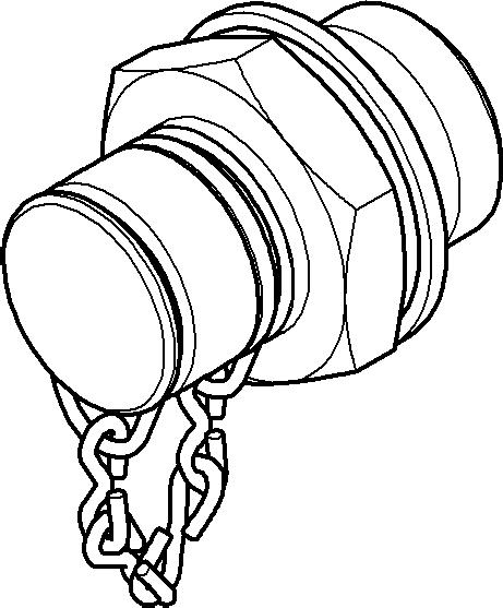
Drain and fill theoil through the service trap
Depending on the machine, the service trap can be different.
1 Oil filling coupling
2 Oil draining coupling
Fill the oil
Release hydraulic pressure.
Usethequickchangecoupling 1ofthe service traptorefillhydraulic oil untilyou get the correct oil level.
Drain the oil
Laydowntheattachmentinordertohaveamaximumquantityofoilinthehydraulic tank: stick and bucket cylinders fully retracted, bucket down. Release hydraulic pressure.
Use the quick change coupling 2 of the service trap.
Add manually small quantities of oil
1 Return-line filter
As a help way, or for small quantities, hydraulic oil can be added manually. Release hydraulic pressure. Remove the cover of the return-line filter 1
Caution! Contamination!
Risk of damage to the hydraulic system. Make sure that the return filter is installed.
Add oil through the return-line filter until you get the correct oil level. Install the cover back.
5.9.5Hydraulic oil coolers
Cleaning hydraulic oil coolers is necessary to get optimum hydraulic oil cooling. Cleanhydraulicoilcoolerswithcompressedairorasteamcleanerattheintervals giveninthecontrol andmaintenancechart,andmoreoftenifworkingconditions make it necessary.
5.9.6Return-line, leak oil and air filters
The return-line filters, the leak oil filter and the air filter are located on the top of the hydraulic tank.
Themagneticrods5ofthetwotypesoffiltersmustbecleanedatfixedintervals(refer to the control and maintenance chart) and the glass fibre filter insert 2 replaced.
Clean the magnetic rod and replace the filter insert
This section is applicable for the two types of filters. Release hydraulic pressure.
Loosen the screws on the filter cover and lift out cover 4 and magnetic rod 5.
Carefully clean any metal particles collection on the magnetic rod 5 Remove the used filter insert 2 on the bracket.
Caution! Contamination!
Risk of damage to the hydraulic system.
Makesurethat dirt,unwantedmaterial or oil whichispossiblydirtydoes not go into the filter housing.
Carefully clean the filter housing.
Insertanewfilterinsertonthebracketverticallyinthetankandpressdownlightly. Then, lay the clamp to the side on the tank ring.
Caution!
Make sure that the filter insert is standing vertical in the tank.
Centrethecoverunitonthefilterinsert2andposition.Makesurethatthesealing 3 is put correctly and it is in good condition.
Thefilling openingofthehydraulictank has areturnpipe.Thispreventsobjectsgetting into the hydraulic tank. The protective cylinder can be removed from the filling opening if necessary.
Eachtimeyoureplacethefilterinsert2,alsoreplacethepressurefilterinsertthat is integrated in the servo oil unit.
Install the cover 4 back.
5.9.7Piloting and replenishing oil filters
Three hydraulic filters do the filtration of the auxiliary circuits:
For the filters replacement interval, refer to the control and maintenance chart. It is not permitted to clean the filter element. Replace the filter element each time you open the filter housing.
Servo oil filter
Theservooilfilterisinstalledonthe servooil unit 1,whichislocated abovethesplitterbox.
Replenishing oil filters
Replacethefilter elements
Release hydraulic pressure before the replacement of the filter elements. Remove the filter housing 2
Remove the filter element 4
Make sure the filter head 6 and housing2 are in good conditions. Insert a new filter element 4
Make sure seals and O-ring 3 are correctly installed. Lightly lubricate the threads of the housing 2
Install the filter housing 2 back. Tighten it with your hand.
5.9.8High pressure filtersin working circuit
Three high pressure filters are installed on the inlet ports of the control valves.
Fig. 5-33 High pressure filter on valve bank
1 High pressure filter
4 Coupling Caution!
The filter elements should be checked or replaced at the intervals specified in the control and maintenance chart
Theconcernedfilterelementsmustbereplacedaftereachreplacementorrepairof a working pump.
Check or replace the filter element
Caution!
Riskofoilspillingwhenremovingthefilterhousing.Oilspillingcouldbereducedby using a vacuum pump.
Fig. 5-34 High pressure filter parts
1
2
3 Compression spring
6
Release hydraulic pressure. Remove the filter housing 6 Removethefilterelement2,checkitandcleanitwithnonflammablecleaningfluid, or replace it if necessary with a new element.
Thefilter element 2 can becleaned up to three times. Thenit must bereplacedby a new one.
Check for leaks each time you check or you replace the filter element: en the filter housing 6 and the filter head 1
Cleanthefilterhousing6andthefilterhead1andinstallitagain,makingsurethe o-rings are correctly installed.
Turn the filter housing 6 in the filter head 4 up to the stop.
Loosen the filter housing 6 by 1/6 turn.
5.9.9Control circuit
It is not necessary to do special maintenance on the control circuit(servo oil circuit).
1 Accumulator
2 Valve blank
Examine the pipe network and connections on all units (pressure accumulator, pressure limiting valve, pressure filter, etc.) regularly for leaks.
As Danger!
Astheaccumulator1keepsthecontrolcircuitunderpressure,thiscontrolpressure must be depressurized as follows before working on the control circuit.
Put the work equipment on the ground.
Stop the motor.
Operate the two joysticks (with ignition key in contact position).
5.9.10Remove the intakehoses from the pumps
If you must remove intake hoses from their related pump or from the hydraulic tank, the hydraulic shutoff valves 1 must be closed.
Remove intake hoses
Release the hydraulic pressure. Close the hydraulic shutoff valve 1
Remove related intake hose.
Drain the hydraulic oil out of the pump and intake hose in a suitable container.
Once the repair work is completed, open the hydraulic shutoff 1
5.9.11Bleeding of hydraulic pumps
After workingon thepumps or after oil changeinthe hydraulic system,thehydraulic pumps must be bled.
Slightlyloosentheplugs(shownbythearrowsinthedrawingsthatfollow)andlet the air to escape.
As soon as hydraulic oil flows out densely, close the plugs again.
Before starting the pump for the first time after repairing or replacing the pump, the pump housing must be filled with hydraulic oil through the same hole.
Bleeding of working pumps
Bleeding of cooling pump
Depending on the machine, the cooling pump can be different.
5.9.12Bleeding the hydraulic cylinders
The cylinders must be bled after each cylinder replacement and after work carried outonthecylinders(replacementofseals,etc.)orthehydrauliccircuits(replacement of hose, etc.).
Start the motor and let it run for the duration of the procedure.
Ifpossible,movetheattachmenttoputthesidetobebled(not-suppliedside)in the upper position.
Slowly extend the cylinder tothe extreme position and then slowly fully retract it again.Makesurethatallmovementsareslowandsmooth.Dothisprocessaminimum of 5 minutes.
Danger!
If the cylinder is not correctly bled, gas bubbles can form inthesystem (mixture of airand hydrocarbon).Athighoperatingpressures inthecylinder,thesegasescan explode (Diesel effect).
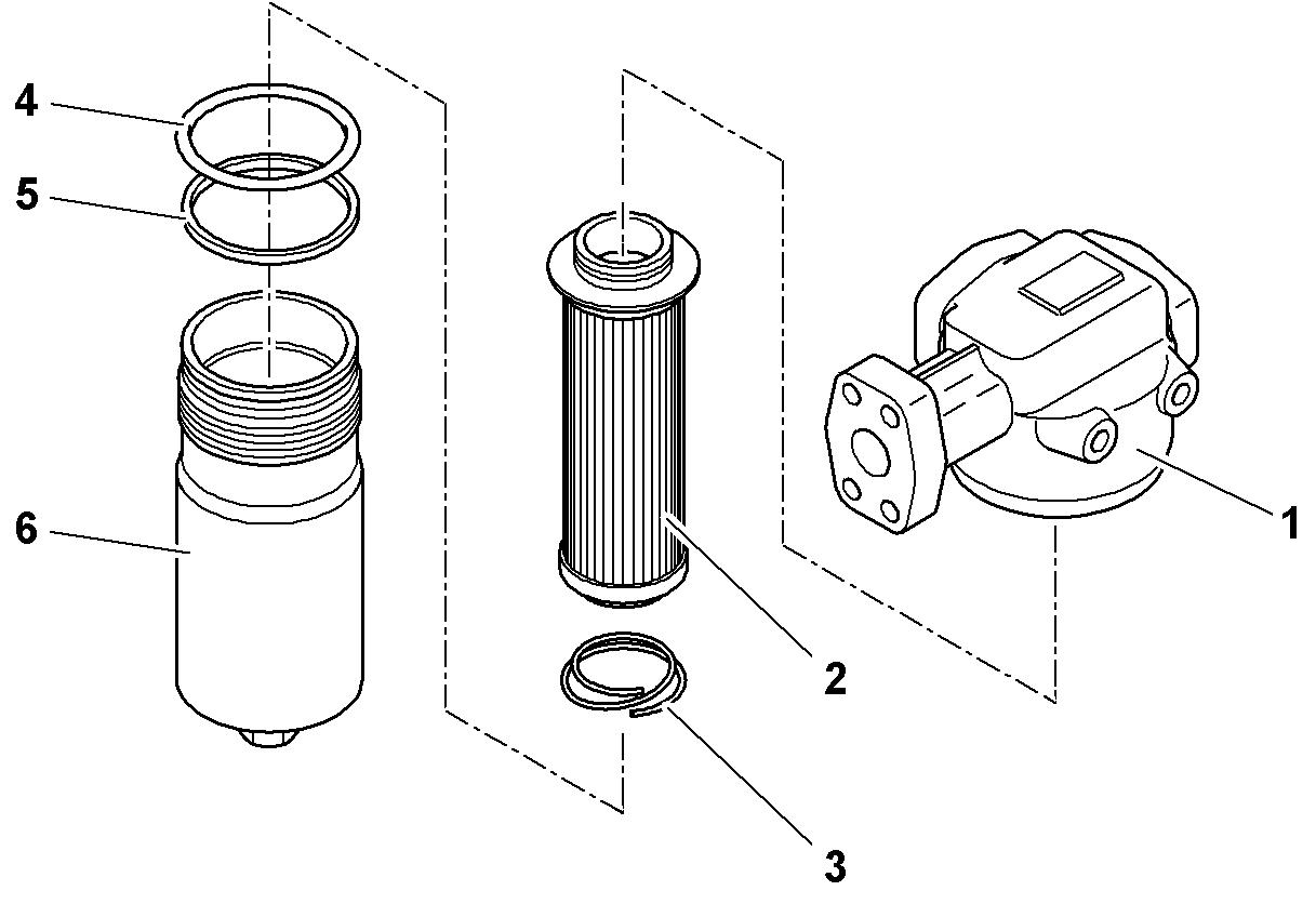
5.9.13Bypass filter for hydraulicoil
1 Nut
2 Cover
3 Magnetic rod
4 Seal ring
5 O-ring
6 Filterelement
7 Filter housing
8 Stud screw
Working environment humidity as well as equipment lowering in water may be responsible for possible water presence in the hydraulic system.
A bypass filter mounted on top of the left catwalk separates this water from the hydraulic system.
Replace a filter element:
Loosen nuts 1
Remove the cover 2.
Remove carefully any dirt from the magnetic rod 3
Check conditionof theseal ring 4 andtheO-ring 5 andchange them if defective.
Remove the used filter element 6
Check the inlet and the outlet in the filter housing 7 and clean if necessary.
Put a new filter element 6 vertically into the housing 7
Install the seal ring 4 and the O-ring 5 again.
Install the cover 2 again.
Tighten nuts 1 with stud screws 8.
5.9.14Oil cooler protection filters (optional)
2 Protection filter
Protectionfilters2can in case of possible hydraulic component failure. reduce the impact on the operating conditions of
Check and clean filters regularly.
Check filters in case of hydraulic component failure. Change filter in case of impact or mesh rupture.
For maintenance intervals, see control and maintenance chart.
Caution!
Iffiltersmaintenanceisnotcorrectlydone,filters cloggingduetoregular operation of the machine could lead to following risks: on oil quality
Check or replace a filter
Makesurethattheshutoffvalvebetweenthehydraulictankandpumpsisclosed. Useavacuumpumpconnectedtothehydraulictankinordertominimizeoilloss. Duringmaintenanceoperation,ifoneorseveralfilter(s)is/aredefective,andifnoreplacementfilterisavailable,themachinecanstillbeoperatedwithoneorseveralfilter(s) missing. This until delivery of a new filter.
Make sure to always have sufficient operational filter in order to reduce maintenance time.
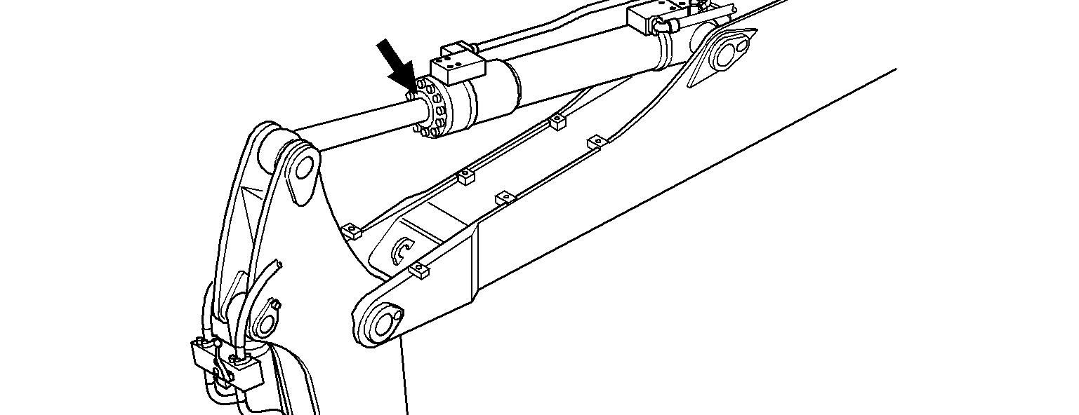
5.9.15Servicing the hydraulic cylinder
Checking the condition of the piston rod mount
Note
When a leak appears on the piston rod mount of a hydraulic cylinder (see arrow), the sealing kit must be replaced by a LIEBHERR fitter.
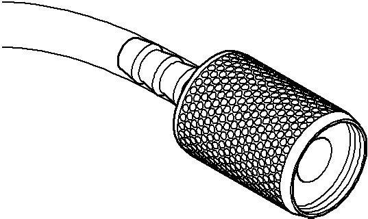
5.9.16Replacement of the hydraulic hoses
Service life
Danger!
Itisnecessarytoreplacethehydraulichosesatspecifiedintervalstomaintaintheir maximum operating performance and to reduce the risk of personal injury and/or machine damage.
Obey the replacement intervals given below.
Natural ageing of the hose assemblies
Two types of hose assemblies are installed on the machine, with different natural ageing:
Critical hoses
The critical hoses are all the hoses in which oil and fuel flow, except the oil suction hoses.
When you check a hose assembly or you install a new one, refer to the date of assembly marked on the hose assembly fittings.
T Date when the hose assembly has been made
T+2 Date T + 2 years
T+4 Date T + 4 years
T+6 Date T + 6 years
Ifthehoseassemblyisinstorage,installitonthemachine(oronapreassembled module) before the date T + 2 years. If not, dispose of it.
Ifthehoseassemblyisinstalledonamachinewhichwasneverin operation, put the hose assembly in operation before the date T + 4 years. If not, dispose of it.
WhenthehoseassemblyisT+ 6years old,disposeofiteven ifitis installedon a working machine.
Non-critical hoses
All other hoses are non-critical:
(coolant,grease,heatingandair-conditioning fluid)
When youcheck a hose assembly or you install a new one, refer to the date of assembly marked on the hose assembly fittings.
T Date when the hose assembly has been made
T+2 Date T + 2 years
T+6 Date T + 6 years
T+8 Date T + 8 years
Ifthehoseassemblyisinstorage,installitonthemachine(oronapreassembled module) before the date T + 2 years. If not, dispose of it.
Ifthehoseassemblyisinstalledonamachinewhichwasneverin operation, put the hose assembly in operation before the date T + 6 years. If not, dispose of it.
WhenthehoseassemblyisT+ 8years old,disposeofiteven ifitis installedon a working machine.
Operating stress
Forthereplacementintervalsgiveninworkinghoursofthehydraulichoses,refer to the section "Control and maintenance chart" of this manual.
3
Danger!
5
6
A defective hydraulic hose can cause accidents and injuries. Replace defectivehydraulic hoses (bubbles,moisture,damagedtop edgeetc.) immediately.
Themountingboltsofthehydrauliclines must be replaced after each removal. Install new hoses in such a way that torsion loading is avoided. Ensure that the hydraulic hose is not twisted when mounting.
Tighten the mounting screws of the SAE fittings with the following tightening torques and respecting the progressive criss-cross tightening procedure described further in this chapter:
Note!
These tightening torque values are also applicable to the mounting screws of the sealing flanges and hydraulic blocks.
SAE half flanges installation
Caution!
SAE half flanges must not touch hose bearing surface.
To install half flanges:
Pre-install first half flange (screw in only by a few threads).
Install seal in hose.
Install hose into bottom of mounted half flange without touching the bearing sur- face.
Put the hose onto the bearing surface. Install the second half flange. Tightenmountingscrewstotheprescribedtorquevalueandby followingtheprogressive criss-cross tightening procedure described further in this chapter.
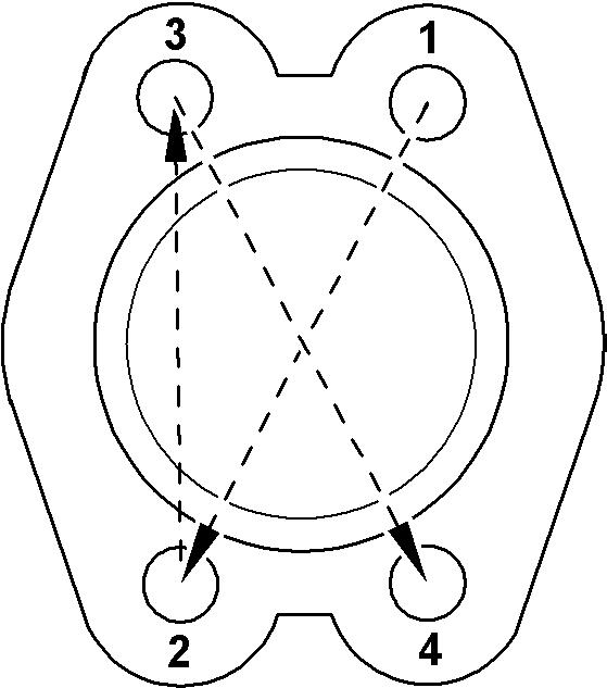
5.9.17Progressive criss-cross tightening procedure
Note!
Always use this procedure to install the following flanges types:
Makesurethat all mountingsurfaces have no damage, greaseorcontamination. Install the O-ring in the groove of the hose fitting. You can use grease to hold the O-ring in position into the groove. Be careful not to apply too much grease because it could look like a leak during operation.
Put the hose in position onto the mounting surface (be careful that you do not cause damage to the O-ring or remove the O-ring).
Pre-install the flange and pre-tighten the mounting screws by hand. Tighten the screws progressively in a criss-cross pattern: d equally: the screw heads must not turn when you apply 100% of the prescribed torque value.
5.10Oil changes on components
5.10.1General information
The machine must be standing level. Stop the electric motor.
Wait briefly until the oil has collected in the oil sump.
Drain off the oil (preferably when oil is at operating temperature)
Add the oil.
Check the oil level.
For oil quality and quantity, refer to the lubricant chart.
For change intervals, refer to the lubrication chart and to the control and maintenance chart.
5.10.2Swing gear – Oil change
1 Oil drain device
2 Oil drain neck
3 Swing gear
4 Filling connection
5 Ventilation connection
Depending on the machines, the oil drain device 1 of the swing gear 3 can be: nnectanadapterwiththecharacteristics that follow:
For oil specifications and oil quantity, refer to the lubrication chart.
For oil change intervals, refer to the control and maintenance chart.
Make sure that the oil is at operating temperature.
Doacheckoftheoillevelthroughthesightgauges8and9oftheexpansiontank. If the oil level is less than the minimum value: Add oil.
Drain theoil
Make sure that the oil is at operating temperature. Removethesealingcap6oftheexpansiontanklocatedonthehydraulictank12.
Remove the oil drain device 1 of the swing gear 3
Attach a drain hose or the related adapter. Drain the oil into an applicable container. Remove the hose or the related adapter. Install the oil drain device 1 back.
Install the sealing cap 6 of the expansion tank back.
Fill the oil
For small quantities
You can fill the oil through the filler tubes 7 on the top on the expansion tank.
Caution!
Risk of damage.
Too much oilin the swing gear can cause damages to the components. Make sure that you fill the correct related expansion tank chamber.
For large quantities
Remove the hoses connected to the ports 4 and 5 of the swing gear. Fill the swing gear with oil through these ports. When the oil level is correct, install the hoses back.
5.10.3Swing gears flushing
Caution!
Gears flushing is necessary when switching from mineral oil to synthetic oil. Use new oil to flush the gear when switching from mineral oil to synthetic oil. Flushing with cleaning fluid or Diesel fuel is not permitted.
To flush the swing gears:
Fill up the swing gear (it is not necessary to fill the line to the expansion tank). Turn the uppercarriage for 1 minute. Drain the oil.
Fill the swing gear again and the expansion tank to correct level.
5.10.4Splitterbox – oil change
To check the oil level in the splitterbox: Turntheelectricmotoroffandwait15minutesfortheoiltocollectintotheoilpan.
Read oil level using the dipstick 2.
Note!
The oil in the splitterbox must be changed via the quick-change coupling 4 on the service trap and when the oil is at operating temperature. Refill the splitterbox up to the mark on dipstick 2. Do not overfill.
For oil specification and oil quantity, refer to the lubrication chart.
For oil-changing intervals, refer to the control and maintenance chart.
To drain the oil:
Use the quick-change coupling 4 on the service trap.
As a help way, the oil can also be changed via the drain valve 1 located at the bottom of the splitterbox:
Remove the cap from the drain valve 1
Screw on a drain hose.
Drain the oil into a suitable container.
Remove the drain hose.
Reinstall the cap on the drain valve 1
To add oil:
Remove the oil inlet cap 3.
Addoilviathethreadedboreholeoftheremovedcap3uptothemarkondipstick 2
When correct oil level is reached, reinstall the oil inlet cap 3.
Make the electric motor run for a few minutes.
Turn the motor off.
Wait a few minutes and recheck the oil level with dipstick 2
5.11Electric rotary connection
Check the mounting screws on the rotary connection and all brackets at the interval specifiedinthemaintenanceschedulefortightness.Thebearingissealedanddoes not need to be lubricated.
The outside of the rotary connection must be cleaned regularly.
Anddirtanddustmustbecleanedfromtheinternalglidingsurfaces,brushesandinsulators.Removeanytraceofcondensationfromtheinsideoftheunit.Replaceseal if necessary.
Use only a vacuum cleaner and dry cotton rag.
Carefullyinspectthesurfaceoftheglidingsurfacesforoxidationorscorch.Because of slow rotation and hardness, the carbon brushes will last a relatively long time. However, they should be checked regularly.
They have to be replaced in time, before the metal part of the brush holder or the mounting screws of the carbon brushes touch the slip rings.
Danger!
Beforeanymaintenance/workorrepaironelectricrotaryconnection,theexcavator must be totally disconnected, locked and tagged out from field switch! For maintenance on HIGH VOLTAGE, refer to § «Electrical system».
5.12Connecting box
Check the mounting screws on the connecting box and all brackets at the interval specified in the maintenance schedule for tightness. The outside of the connection box must be cleaned regularly.
Anydirtanddustmustbecleaned,removeanytraceofcondensationfromtheinside of the unit. Replace seal if necessary.
Use only a vacuum cleaner and only the Liebherr specific cleaning kit including appropriate cleaning products (Id. 10491289).
5.13Electrical boxes S1 and S2
Proceed to cleaning and maintenance on S1 and S2 boxes at the interval specified in the «Control and maintenance chart». Replace filter if necessary.
Use only a vacuum cleaner and only the Liebherr specific cleaning kit including appropriate cleaning products (Id. 10491289).
Danger!
Beforeanymaintenance/workorrepaironelectricrotaryconnection,theexcavator must be totally disconnected, locked and tagged out from field switch! For maintenance on HIGH VOLTAGE, refer to § «Electrical system».