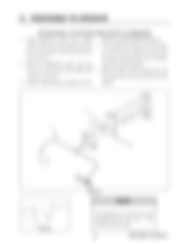
IV. PREPARING TO OPERATE ATTACHING LS SYSTEM AND DEPTH COMMAND 1. Install Tasseltrol®/LS sensor mount support
diagram in the Hagie 204SP Parts Manual.
weldment with the two nylon washers (fig. 4.23,
4. Turn the ignition key switch to the “ON” position
item 2) in the forward– most hole of the tool bar
to check the sensor installation. DO NOT start
(fig. 4.23, item 1).
the engine. See page 59 for more information
2. Install the Tasseltrol®/LS sensor mount (fig.
about the LS sensor assembly.
4.23, item 3) to the sensor mount support weld-
5. Attach the depth command actuator (fig. 4.24)
ment (fig. 4.23, item 2).
to the light sensor mount and the tool bar. See
3. Install the cable assembly according to the wire
page 60.
1
3 2
FIG 4.23
NOTE: Over tightening of the sensor arm pivot mounting bolt (fig. 4.23, item 1) may cause the actuator to stall. FIG 4.24
33
PREPARING TO OPERATE


