TMS800E OPERATOR’S MANUAL
SET-UP AND INSTALLATION
1.
Lower boom below horizontal.
6.
2.
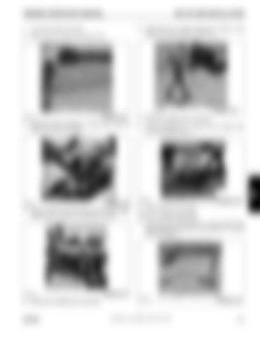
Attach tag line to stinger nose Figure 4-35.
Using tag line to control movement of stinger, swing stinger into stowed position Figure 4-38.
1
FIGURE 4-38
6642-29
FIGURE 4-35
6642-23
3.
Disconnect LMI connection (1, Figure 4-36). Stow the cable in the 23 ft (7 m) section.
7.
Raise boom slightly above horizontal.
8.
Connect stowage link (1, Figure 4-39) to stinger using pin (2) and retainer clip (3).
2 1
3
6642-28
4.
6642-24
1
FIGURE 4-39
FIGURE 4-36
Remove retainer clip and remove the left side stinger retaining pin (1, Figure 4-37). Place pin in holder.
9.
Remove tag line from stinger.
33 ft (10.1 m) Boom Extension 1.
Lower boom and secure tag line (1, Figure 4-40) to tip of boom extension. shows the 7 m (23 ft) and 10.1 m (33 ft) extension together.
1
6642-26
FIGURE 4-37 6642-30
5.
Raise boom to slightly above horizontal.
GROVE
Published 12-22-2008, Control # 107-09
1
FIGURE 4-40
4-17
4


