1 minute read
TMS800E OPERATOR’S MANUALSET-UP AND INSTALLATION


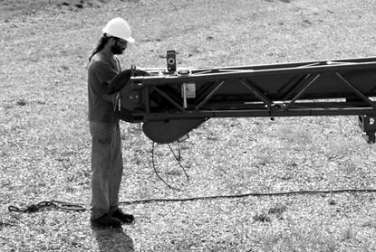
b. Remove dummy plug (1, Figure4-27) from junction box on boom nose.
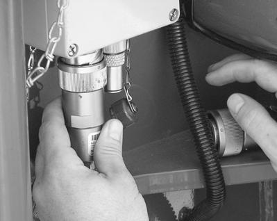
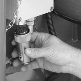
Install cable end connector (1, Figure4-28) from boom extension where dummy plug was removed.
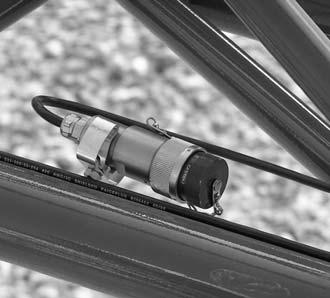
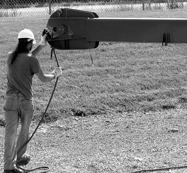
19. Connect LMI cables: a. Remove LMI cable end connector (1, Figure4-26) from extension and route through boom extension.
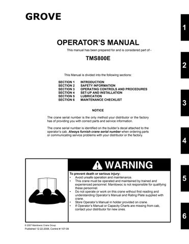
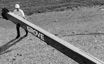
20. Lower boom and remove tag line (1, Figure4-29) from the tip of the extension. Figure4-29 shows the 7 m (23 ft) and 10.1 m (33 ft) section together.
56 ft (17.1 m) Boom Extension
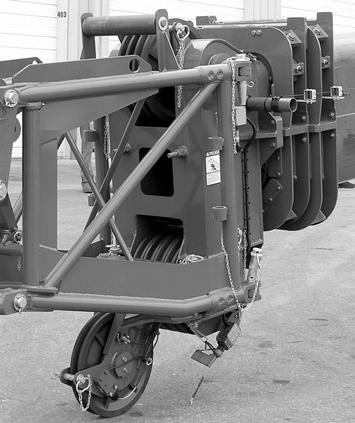
1. Secure tag line to (1, Figure4-30) bi-fold nose.
NOTE: Do not lower boom until stinger has been completely swung in front of the 33 ft (10.1 m) section.
5. Lower the boom.
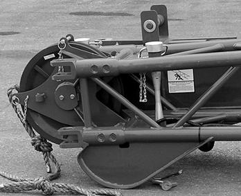
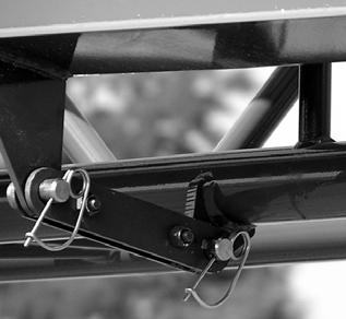
6. Remove pin (1, Figure4-33) from swingaway. Install pin in stinger and retain with clip pin.
2. Raise boom slightly above horizontal.
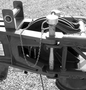
3. Remove retainer clip (1, Figure4-31) and remove bi-fold stowage pin (2).
7. Connect LMI connector (1, Figure4-34) to LMI connection box. The cable is stowed in the 23 ft (7m) section.
4. Using the tag line (1, Figure4-32) to maintain control of the bi-fold (stinger), swing stinger into erected position.
8. Remove tag line before operating crane.
NOTE: Reeve the hoist cable as described under rigging and unrigging procedure in this section.
Stowing Procedure

56 ft (17.1 m) Boom Extension
Danger
To prevent serious injury or death, do not stand on decking until extensions are secure.