4 minute read
TMS800E OPERATOR’S MANUALOPERATING CONTROLS AND PROCEDURES


deposits on the valves, pistons and rings; and rapid accumulation of sludge in the engine.
NOTE: When prolonged engine idling is necessary, maintain at least 800 rpm.
NOTE: After prolonged idle, you may notice momentary white vapor and an odor. This is normal.
Racing The Engine
DO NOT race the engine during the warm-up period or operate the engine beyond governed speed (as might occur in downhill operation or dow nshifting). Engine bearings, pistons, and valves may be damaged if these precautions are not taken.
Shutdown Procedure
1. Allow the engine to run at fast idle speed for about five minutes to avoid high internal heat rise and allow for heat dissipation.
2. Position the ignition switch to off (vertical position).
3. Drain the fuel filter-water separator.
Exhaust Regeneration
The engine utilizes a particulate filter in the exhaust system for the reduction of emissions. Under normal operation, the engine runs hot enough to turn soot into carbon dioxide and the particulates do not clog the filter. If the exhaust is not hot enough, the filter begins to clog and the exhaust filter light illuminates. If possible, the crane can be run on a road duty at normal highway speeds to increase engine temperature and engage the automatic regeneration process. If regeneration does not occur, the exhaust regeneration light will begin to flash. Eventually, if regeneration does not occur, the Engine Warning light will also illuminate and regeneration will have to take place.
Warning
During regeneration, exhaust temperatures may reach 800° C (1500° F) which is hot enough to ignite or melt common materials. Do not park the vehicle over combustible materials and keep all materials at least 0.6m (2 ft.) away from the exhaust outlet.
Exhaust regeneration is automatic and can occur while parked or driving. Engine speed will increase and possibly reach between 1000 and 1500 rpm. Also, a reduction in power might be noticed.
General Crane Operation Pump Drive
The main No. 1 hydraulic pump is driven by an engine PTO. The two-section No. 2 hydraulic pump is direct engine driven.
Control Lever Operation
The control lever operation for crane functions is proportional, i.e., the closer the lever is to neutral (center), the slower the system responds. Return the control lever to neutral to hold the load. Do not feather the hoist control to hold the load.
NOTE: Always operate the control levers with slow, even pressure.
Preload Check
After the crane has been readied for service, an operational check of all crane functions (with no load applied) should be performed. Preload check is as follows:
• Extend and set the outriggers and level the crane.
• Raise, lower, and swing the boom right and left at least 45 degrees.
• Telescope the boom out and back in, ensuring all sections extend and retract properly.
• Raise and lower the cable a few times at various boom lengths. Make sure there are no kinks and that the cable is spooling on the hoist properly.
Caution
Run the engine at or near the governed RPM during operation of all crane functions.
NOTE: Carefully read and become familiar with all crane operating instructions before and operating the crane.
Using Your Load Chart
NOTE: One of the most important tools of every Grove Manitowoc crane is the load chart found in the crane operator's cab.
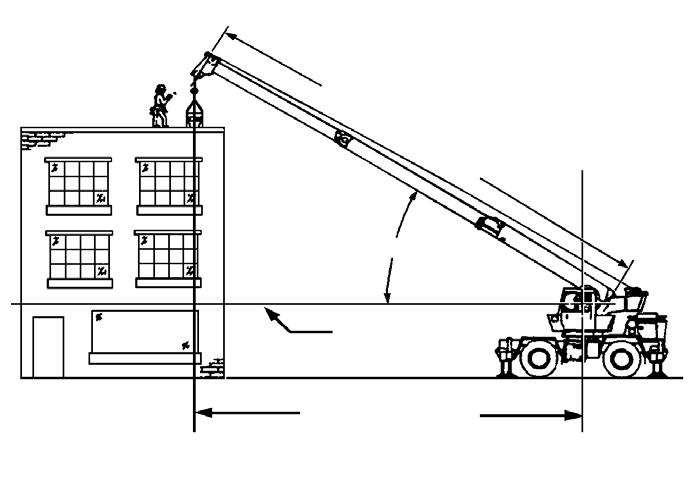
NOTE: Refer to (Figure 3-4) for terms to know in determining lifting capacities.
The load chart contains the lifting capacities of the crane in all allowable lifting configurations, and must be thoroughly understood by the operator.
The load chart is divided into capabilities limited by crane structural strength and stability which is shown by a bold line across the chart. Structural strength limits are above the line and stability limits are below the line.
Published 12-22-2008, Control # 107-09
The left column is the load radius, which is the distance from the axis of the crane rotation to the load center of gravity. The top row lists various boom lengths from fully retracted to fully extended (with swingaway extension). The number at the intersection of the left column and top row is the total load limit for that load radius and boom length. The number in parentheses below the total load limit is the required boom angle (in degrees) for that load. Boom lengths between increments should always be treated as if it were the next longer length. For example, if the actual boom length is 15.2 m (50 ft) and the chart shows boom lengths of 14.6 - 16.4 m (48 - 54 ft), use the load capacity shown in the 16.4 m (54 ft) column.
Another important section is the range diagram. The range diagram shows the operating radius and tip height that can be achieved at a given boom length and angle. If the operator knows the radius and tip height required for a specific lift, the angle and boom length can quickly be determined from the range diagram. Or if he knows the boom length and angle, he can quickly determine the tip height and operating radius.
A lifting diagram is included for over-side, over-rear, and over-front lifting areas. The lifting area diagram shows that the locations of the outrigger stabilizer cylinders in the full extended position are used to mark the boundaries of the lifting areas.
Another section contains notes for lifting capacities. Be sure to read and understand all notes concerning lifting capacities.
The load chart also gives weight reductions for Manitowoc/ Grove load handling devices such as hookblocks, overhaul balls, boom extension sections, etc, which must be considered as part of the load. The weight of any other load handling devices such as chains, slings, or spreader bars must also be added to the weight of the load.